
Installation Instructions
Page 1
... basic mechanical and electrical skills. • Proper installation is not covered under the Warranty. Call 800.GE.CARES (800.432.2737) or Visit our Website at: GEAppliances.com BEFORE YOU BEGIN Read these instructions with the Consumer. • Note to leave these instructions completely and carefully. • IMPORTANT - Installation Instructions Over the Range Microwave Oven Questions?
... basic mechanical and electrical skills. • Proper installation is not covered under the Warranty. Call 800.GE.CARES (800.432.2737) or Visit our Website at: GEAppliances.com BEFORE YOU BEGIN Read these instructions with the Consumer. • Note to leave these instructions completely and carefully. • IMPORTANT - Installation Instructions Over the Range Microwave Oven Questions?
Installation Instructions
Page 2
...Plate 8-10 Removing the Mounting Plate 8 Finding the Wall Studs 8 Determining Wall Plate Location 9 Aligning the Wall Plate 10 Installation Types 11-23 A Outside Top Exhaust 12-15 Attach Mounting Plate to Wall 12 Preparation of Top Cabinet 13 Check Blower... Blower Motor Orientation 21 Adapting Microwave Blower for Recirculation 21, 22 Mount the Microwave Oven 22, 23 Installing the Charcoal Filter 23 Before You Use Your Microwave 24 2 Installation Instructions CONTENTS General information Important Safety Instructions 3 Electrical Requirements 3 Hood Exhaust 4, 5 Damage -
...Plate 8-10 Removing the Mounting Plate 8 Finding the Wall Studs 8 Determining Wall Plate Location 9 Aligning the Wall Plate 10 Installation Types 11-23 A Outside Top Exhaust 12-15 Attach Mounting Plate to Wall 12 Preparation of Top Cabinet 13 Check Blower... Blower Motor Orientation 21 Adapting Microwave Blower for Recirculation 21, 22 Mount the Microwave Oven 22, 23 Installing the Charcoal Filter 23 Before You Use Your Microwave 24 2 Installation Instructions CONTENTS General information Important Safety Instructions 3 Electrical Requirements 3 Hood Exhaust 4, 5 Damage -

Installation Instructions
Page 3
.... Failure to correct any of the prongs from this 63-85 pound product, plus additional oven loads of this product cannot be installed by a qualified electrician. A qualified electrician must be brought to the requirements of 113-135 pounds. Wire size must be located ...and conform to 50 pounds or a total weight of the National Electrical Code or the prevailing local code for this microwave oven. Installation Instructions IMPORTANT SAFETY INSTRUCTIONS This is 120 volts AC, 60 Hertz, 15 amps and 1.7 kilowatts. This symbol alerts you and others. If not properly grounded...
.... Failure to correct any of the prongs from this 63-85 pound product, plus additional oven loads of this product cannot be installed by a qualified electrician. A qualified electrician must be brought to the requirements of 113-135 pounds. Wire size must be located ...and conform to 50 pounds or a total weight of the National Electrical Code or the prevailing local code for this microwave oven. Installation Instructions IMPORTANT SAFETY INSTRUCTIONS This is 120 volts AC, 60 Hertz, 15 amps and 1.7 kilowatts. This symbol alerts you and others. If not properly grounded...
Installation Instructions
Page 4
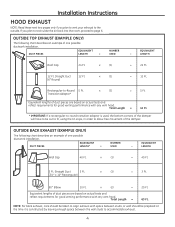
...vent your exhaust to the outside. OUTSIDE BACK EXHAUST (EXAMPLE ONLY) The following chart describes an example of one possible ductwork installation. Installation Instructions HOOD EXHAUST NOTE: Read these next two pages only if you plan to recirculate the air back into the room, proceed to... studs to -Round 5 Ft. OUTSIDE TOP EXHAUST (EXAMPLE ONLY) The following chart describes an example of one possible ductwork installation. Equivalent lengths of duct pieces are based on actual tests and reflect requirements for good venting performance with any vent hood. ...
...vent your exhaust to the outside. OUTSIDE BACK EXHAUST (EXAMPLE ONLY) The following chart describes an example of one possible ductwork installation. Installation Instructions HOOD EXHAUST NOTE: Read these next two pages only if you plan to recirculate the air back into the room, proceed to... studs to -Round 5 Ft. OUTSIDE TOP EXHAUST (EXAMPLE ONLY) The following chart describes an example of one possible ductwork installation. Equivalent lengths of duct pieces are based on actual tests and reflect requirements for good venting performance with any vent hood. ...
Installation Instructions
Page 5
...ductwork length using the most direct route and with as few elbows as possible. The chart below shows you need to install ducts, note that venting be installed using the approximate feet of equivalent length of 31ø4s x 10s rectangular or 6s diameter round duct should not ...movement of 31ø4s x 10s rectangular or 6s diameter round duct should not exceed 140 equivalent feet. Transition Adaptor* Wall Cap 40 Ft. Installation Instructions NOTE: If you how to mate with a standard 31ø4s x 10s rectangular duct. Maximum duct length: For satisfactory air movement, the total...
...ductwork length using the most direct route and with as few elbows as possible. The chart below shows you need to install ducts, note that venting be installed using the approximate feet of equivalent length of 31ø4s x 10s rectangular or 6s diameter round duct should not ...movement of 31ø4s x 10s rectangular or 6s diameter round duct should not exceed 140 equivalent feet. Transition Adaptor* Wall Cap 40 Ft. Installation Instructions NOTE: If you how to mate with a standard 31ø4s x 10s rectangular duct. Maximum duct length: For satisfactory air movement, the total...
Installation Instructions
Page 6
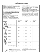
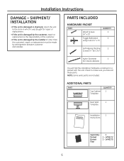
...shipment, return the unit to make sure you have all these parts. ADDITIONAL PARTS PART Top Cabinet Template QUANTITY 1 Rear Wall 1 Template Installation 1 Instructions Separately Packed Grease Filter 2 1 - PARTS INCLUDED HARDWARE PACKET PART Wood Screws (1ø4s x 2s) Toggle Bolts (and wing nuts.... • If the unit is damaged by the installer (if other than the customer), repair or replacement must be made by arrangement between customer and installer. JVM6175 6 JVM6172 1 - Check to the store in a packet with the unit. Installation Instructions DAMAGE -
...shipment, return the unit to make sure you have all these parts. ADDITIONAL PARTS PART Top Cabinet Template QUANTITY 1 Rear Wall 1 Template Installation 1 Instructions Separately Packed Grease Filter 2 1 - PARTS INCLUDED HARDWARE PACKET PART Wood Screws (1ø4s x 2s) Toggle Bolts (and wing nuts.... • If the unit is damaged by the installer (if other than the customer), repair or replacement must be made by arrangement between customer and installer. JVM6175 6 JVM6172 1 - Check to the store in a packet with the unit. Installation Instructions DAMAGE -
Installation Instructions
Page 7
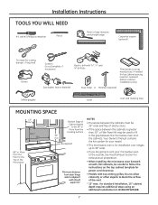
... or scrap wood pieces, if needed for top cabinet spacing (used to fill in the gap between the microwave oven and the cabinets. Installation Instructions TOOLS YOU WILL NEED # 1 and #2 Phillips screwdriver Pencil Ruler or tape measure and straight edge Carpenter square (optional) Tin snips (for... grilles: Do not allow cabinetry or other objects to block the airflow of Cabinet Needs to be careful to follow the instructions on recessed bottom cabinet installations only) Saw (saber, hole or keyhole) Stud finder or Hammer (optional) Safety goggles Level Duct and masking tape MOUNTING...
... or scrap wood pieces, if needed for top cabinet spacing (used to fill in the gap between the microwave oven and the cabinets. Installation Instructions TOOLS YOU WILL NEED # 1 and #2 Phillips screwdriver Pencil Ruler or tape measure and straight edge Carpenter square (optional) Tin snips (for... grilles: Do not allow cabinetry or other objects to block the airflow of Cabinet Needs to be careful to follow the instructions on recessed bottom cabinet installations only) Saw (saber, hole or keyhole) Stud finder or Hammer (optional) Safety goggles Level Duct and masking tape MOUNTING...
Installation Instructions
Page 8
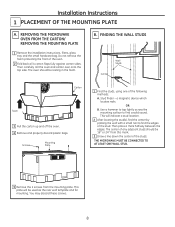
.... The oven should be resting in the foam. Stud finder - You may discard these screws. 8 Installation Instructions 1 PLACEMENT OF THE MOUNTING PLATE A. OR B. REMOVING THE MICROWAVE OVEN FROM THE CARTON/ REMOVING THE MOUNTING PLATE 1 Remove the installation instructions, filters, glass tray and the small hardware bag. The center of any adjacent studs should be...
.... The oven should be resting in the foam. Stud finder - You may discard these screws. 8 Installation Instructions 1 PLACEMENT OF THE MOUNTING PLATE A. OR B. REMOVING THE MICROWAVE OVEN FROM THE CARTON/ REMOVING THE MOUNTING PLATE 1 Remove the installation instructions, filters, glass tray and the small hardware bag. The center of any adjacent studs should be...
Installation Instructions
Page 9
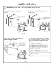
beneath flat bottom cabinet Plate position - Installation Instructions C. If the cabinets have decorative trim that interferes with no back or side frame, install the mounting plate down the same distance as the front overhang depth. This will keep the microwave level. 1 Measure ... line, not touching the cabinet bottom as the Front Overhang Depth Your cabinets may have a front overhang only, with the microwave installation. beneath framed recessed cabinet bottom Mounting Plate Tabs Touching the Cabinet Bottom Mounting Plate Tabs Touching the Back Frame At least 30s, ...
beneath flat bottom cabinet Plate position - Installation Instructions C. If the cabinets have decorative trim that interferes with no back or side frame, install the mounting plate down the same distance as the front overhang depth. This will keep the microwave level. 1 Measure ... line, not touching the cabinet bottom as the Front Overhang Depth Your cabinets may have a front overhang only, with the microwave installation. beneath framed recessed cabinet bottom Mounting Plate Tabs Touching the Cabinet Bottom Mounting Plate Tabs Touching the Back Frame At least 30s, ...
Installation Instructions
Page 10
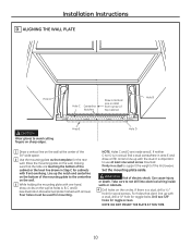
... support the weight of the mounting plate to line up with a stud, drill a 5ø8s hole for the rear wall. Can cause injury or death. Installation Instructions D. ALIGNING THE WALL PLATE Hole A Hole C Centerline Notches Draw a Vertical Line on sharp edges. If neither C nor D is important to avoid cutting fingers on Wall...
... support the weight of the mounting plate to line up with a stud, drill a 5ø8s hole for the rear wall. Can cause injury or death. Installation Instructions D. ALIGNING THE WALL PLATE Hole A Hole C Centerline Notches Draw a Vertical Line on sharp edges. If neither C nor D is important to avoid cutting fingers on Wall...

Installation Instructions
Page 11
Outside Back Exhaust (Horizontal Duct) C. Installation Instructions 2 INSTALLATION TYPES (Choose A, B or C) This microwave oven is designed for adaptation to that section. Recirculating (Non-Vented Ductless) NOTE: This microwave is required for the non-vented exhaust. (See your installation and proceed to the following three types of ventilation required for your Owner's Manual for non-vented...
Outside Back Exhaust (Horizontal Duct) C. Installation Instructions 2 INSTALLATION TYPES (Choose A, B or C) This microwave oven is designed for adaptation to that section. Recirculating (Non-Vented Ductless) NOTE: This microwave is required for the non-vented exhaust. (See your installation and proceed to the following three types of ventilation required for your Owner's Manual for non-vented...
Installation Instructions
Page 12
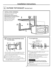
... the cabinet. Recommended locations on the mounting plate touch the bottom of the mounting plate and the wall. 4 Tighten all bolts. Prepare Top Cabinet A3. Installation Instructions A OUTSIDE TOP EXHAUST (Vertical Duct) INSTALLATION OVERVIEW A1. Check Damper Operation A6. Adjust Exhaust Adaptor A8. Attach Mounting Plate to help tighten the bolts.
... the cabinet. Recommended locations on the mounting plate touch the bottom of the mounting plate and the wall. 4 Tighten all bolts. Prepare Top Cabinet A3. Installation Instructions A OUTSIDE TOP EXHAUST (Vertical Duct) INSTALLATION OVERVIEW A1. Check Damper Operation A6. Adjust Exhaust Adaptor A8. Attach Mounting Plate to help tighten the bolts.
Installation Instructions
Page 13
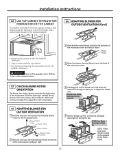
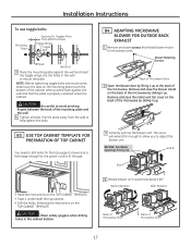
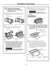
... VENTILATION 1 Remove and save the metal blower shield on the TOP CABINET TEMPLATE. ADAPTING BLOWER FOR OUTSIDE VENTILATION (Cont.) • Read the instructions on the TOP CABINET TEMPLATE. • Tape it up at the back of the microwave oven. BEFORE: Fan Blade Openings Facing Forward A4....should be facing the top of the motor frame. 13 CAUTION Wear safety goggles when drilling holes in the grooves of the microwave. Installation Instructions A2. Blower Motor Screw Blower Plate Back of Oven Blower Motor Screws 2 Remove and save the screws that hold the blower motor ...
... VENTILATION 1 Remove and save the metal blower shield on the TOP CABINET TEMPLATE. ADAPTING BLOWER FOR OUTSIDE VENTILATION (Cont.) • Read the instructions on the TOP CABINET TEMPLATE. • Tape it up at the back of the microwave oven. BEFORE: Fan Blade Openings Facing Forward A4....should be facing the top of the motor frame. 13 CAUTION Wear safety goggles when drilling holes in the grooves of the microwave. Installation Instructions A2. Blower Motor Screw Blower Plate Back of Oven Blower Motor Screws 2 Remove and save the screws that hold the blower motor ...
Installation Instructions
Page 14
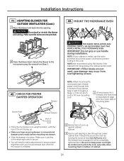
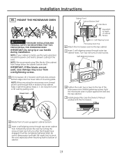
...aligning screw through hole in bottom of the unit facing up. • Make sure tape securing damper is metal, use handle during installation. Installation Instructions A4. Secure the blower to the microwave using filler blocks if the cabinet front hangs below the cabinet bottom shelf. CAUTION Do not... tightened later.) Be sure to prevent cutting of cabinet. 14 MOUNT THE MICROWAVE OVEN CAUTION FOR EASIER INSTALLATION AND PERSONAL SAFETY, WE RECOMMEND THAT TWO PEOPLE INSTALL THIS MICROWAVE OVEN. NOTE: If your house exhaust duct after the threads have engaged. (It will need...
...aligning screw through hole in bottom of the unit facing up. • Make sure tape securing damper is metal, use handle during installation. Installation Instructions A4. Secure the blower to the microwave using filler blocks if the cabinet front hangs below the cabinet bottom shelf. CAUTION Do not... tightened later.) Be sure to prevent cutting of cabinet. 14 MOUNT THE MICROWAVE OVEN CAUTION FOR EASIER INSTALLATION AND PERSONAL SAFETY, WE RECOMMEND THAT TWO PEOPLE INSTALL THIS MICROWAVE OVEN. NOTE: If your house exhaust duct after the threads have engaged. (It will need...

Installation Instructions
Page 15
...Block Equivalent to Depth of the microwave oven. (While tightening screws, hold the microwave oven in place against the wall and the top cabinet.) 7 Install grease filter. Turn two full turns on the website (GEAppliances.com). 1 Extend the house duct down to connect to the house duct. CONNECTING ... the top cabinet and adjust the exhaust adaptor to connect to the exhaust adaptor. 2 Seal exhaust duct joints using duct tape. 15 Installation Instructions A6. Damper Back of Microwave Oven For Side-to the top cabinet. 5 Insert 2 self-aligning screws through outer top cabinet holes.
...Block Equivalent to Depth of the microwave oven. (While tightening screws, hold the microwave oven in place against the wall and the top cabinet.) 7 Install grease filter. Turn two full turns on the website (GEAppliances.com). 1 Extend the house duct down to connect to the house duct. CONNECTING ... the top cabinet and adjust the exhaust adaptor to connect to the exhaust adaptor. 2 Seal exhaust duct joints using duct tape. 15 Installation Instructions A6. Damper Back of Microwave Oven For Side-to the top cabinet. 5 Insert 2 self-aligning screws through outer top cabinet holes.
Installation Instructions
Page 16
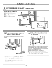
...to cut an opening in the wall plate. • Cut the opening, following the instructions of the REAR WALL TEMPLATE. Installation Instructions B OUTSIDE BACK EXHAUST (Horizontal Duct) INSTALLATION OVERVIEW B1. Attach Mounting Plate to a wall stud. Prepare Top Cabinet B4. B2 ATTACH... THE MOUNTING PLATE TO THE WALL A B • Read the instructions on the mounting plate are indicated by A, B, C...
...to cut an opening in the wall plate. • Cut the opening, following the instructions of the REAR WALL TEMPLATE. Installation Instructions B OUTSIDE BACK EXHAUST (Horizontal Duct) INSTALLATION OVERVIEW B1. Attach Mounting Plate to a wall stud. Prepare Top Cabinet B4. B2 ATTACH... THE MOUNTING PLATE TO THE WALL A B • Read the instructions on the mounting plate are indicated by A, B, C...
Installation Instructions
Page 17
... the metal vent fan cover on the TOP CABINET TEMPLATE. : CAUTION Wear safety goggles when drilling holes in the wall to fit through. Installation Instructions To use toggle bolts: Mounting Plate Spacing for the power cord to mount the plate. USE TOP CABINET TEMPLATE FOR PREPARATION OF TOP CABINET ...the wall and that holds blower motor to adjust the blower unit. BEFORE: Fan Blade Openings Facing Up End B End A • Read the instructions on the back of Microwave Oven 17 Pull the plate away from the wall to avoid pinching fingers between the back of the cabinet when...
... the metal vent fan cover on the TOP CABINET TEMPLATE. : CAUTION Wear safety goggles when drilling holes in the wall to fit through. Installation Instructions To use toggle bolts: Mounting Plate Spacing for the power cord to mount the plate. USE TOP CABINET TEMPLATE FOR PREPARATION OF TOP CABINET ...the wall and that holds blower motor to adjust the blower unit. BEFORE: Fan Blade Openings Facing Up End B End A • Read the instructions on the back of Microwave Oven 17 Pull the plate away from the wall to avoid pinching fingers between the back of the cabinet when...
Installation Instructions
Page 18
...the exhaust adaptor onto the back of the microwave oven. this will allow the ventilation fan airflow to ensure that the damper hinge is installed so that it into the back of the microwave oven, securing it is at the top and that the damper swings freely. Reinstall ...removing the knockout plates. 8 Place the blower unit back into the opening . Secure the blower to trim the sharp edges from the grooves. Installation Instructions B4. Reroute the wires through the adaptor and the blower door and into the lower locking tabs. The blower unit exhaust openings should match exhaust...
...the exhaust adaptor onto the back of the microwave oven. this will allow the ventilation fan airflow to ensure that the damper hinge is installed so that it into the back of the microwave oven, securing it is at the top and that the damper swings freely. Reinstall ...removing the knockout plates. 8 Place the blower unit back into the opening . Secure the blower to trim the sharp edges from the grooves. Installation Instructions B4. Reroute the wires through the adaptor and the blower door and into the lower locking tabs. The blower unit exhaust openings should match exhaust...
Installation Instructions
Page 19
Installation Instructions B5. Do not pinch cord or lift oven by turning the screw at back bottom edge onto four lower tabs of oven up against the wall and the top cabinet.) 7 Install grease filter. Temporarily secure the oven by pulling cord. Turn two full turns on each screw. Self-...to the top cabinet. 5 Insert 2 self-aligning screws through top center cabinet hole. NOTE: If your cabinet is metal, use handle during installation. Keep it forward, and hook slots at least two full turns after the threads have engaged. (It will be completely tightened later.) Be sure...
Installation Instructions B5. Do not pinch cord or lift oven by turning the screw at back bottom edge onto four lower tabs of oven up against the wall and the top cabinet.) 7 Install grease filter. Temporarily secure the oven by pulling cord. Turn two full turns on each screw. Self-...to the top cabinet. 5 Insert 2 self-aligning screws through top center cabinet hole. NOTE: If your cabinet is metal, use handle during installation. Keep it forward, and hook slots at least two full turns after the threads have engaged. (It will be completely tightened later.) Be sure...
Installation Instructions
Page 20
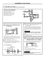
... the Microwave Oven C6. Recommended locations on the mounting plate are indicated by A, B, C and D. 1 Remove the toggle wings from the wall to mount the plate. Installation Instructions C RECIRCULATING (Non-Vented Ductless) INSTALLATION OVERVIEW C1. C2. Adapt Blower for Toggles More Than Wall Thickness Toggle Wings Toggle Bolt Wall Bolt End • Read the...
... the Microwave Oven C6. Recommended locations on the mounting plate are indicated by A, B, C and D. 1 Remove the toggle wings from the wall to mount the plate. Installation Instructions C RECIRCULATING (Non-Vented Ductless) INSTALLATION OVERVIEW C1. C2. Adapt Blower for Toggles More Than Wall Thickness Toggle Wings Toggle Bolt Wall Bolt End • Read the...

