
Installation Instructions
Page 1
... EMPIEZA EN LA P·GINA 25. Call 800.GE.CARES (800.432.2737) or Visit our Website at: GEAppliances.com BEFORE YOU BEGIN Read these instructions for future reference. • Skill level - READ CAREFULLY. Observe all governing codes and ordinances. • Note to Installer - Save these instructions completely and carefully. • IMPORTANT...
... EMPIEZA EN LA P·GINA 25. Call 800.GE.CARES (800.432.2737) or Visit our Website at: GEAppliances.com BEFORE YOU BEGIN Read these instructions for future reference. • Skill level - READ CAREFULLY. Observe all governing codes and ordinances. • Note to Installer - Save these instructions completely and carefully. • IMPORTANT...
Installation Instructions
Page 2
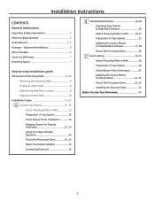
... Placement of Mounting Plate 8-10 Removing the Mounting Plate 8 Finding the Wall Studs 8 Determining Wall Plate Location 9 Aligning the Wall Plate 10 Installation Types 11-23 A Outside Top Exhaust 12-15 Attach Mounting Plate to Wall 12 Preparation of Top Cabinet 13 Check Blower Motor Orientation 13 Adapting ... Wall 20 Preparation of Top Cabinet 20 Check Blower Motor Orientation 21 Adapting Microwave Blower for Recirculation 21, 22 Mount the Microwave Oven 22, 23 Installing the Charcoal Filter 23 Before You Use Your Microwave 24 2
... Placement of Mounting Plate 8-10 Removing the Mounting Plate 8 Finding the Wall Studs 8 Determining Wall Plate Location 9 Aligning the Wall Plate 10 Installation Types 11-23 A Outside Top Exhaust 12-15 Attach Mounting Plate to Wall 12 Preparation of Top Cabinet 13 Check Blower Motor Orientation 13 Adapting ... Wall 20 Preparation of Top Cabinet 20 Check Blower Motor Orientation 21 Adapting Microwave Blower for Recirculation 21, 22 Mount the Microwave Oven 22, 23 Installing the Charcoal Filter 23 Before You Use Your Microwave 24 2

Installation Instructions
Page 3
...to avoid severe or fatal shock. The outlet box and supply circuit should be replaced with a properly grounded three-prong wall receptacle, installed by a qualified electrician and conform to the National Electrical Code or the prevailing local code. Do not use The power cord of electric... of 113-135 pounds. This product must be connected to BOTH a top cabinet AND a wall. The power supply cord and plug should be installed in cabinet arrangements such as : DANGER Indicates a hazardous situation which , if not avoided, could result in minor or moderate injury. All safety ...
...to avoid severe or fatal shock. The outlet box and supply circuit should be replaced with a properly grounded three-prong wall receptacle, installed by a qualified electrician and conform to the National Electrical Code or the prevailing local code. Do not use The power cord of electric... of 113-135 pounds. This product must be connected to BOTH a top cabinet AND a wall. The power supply cord and plug should be installed in cabinet arrangements such as : DANGER Indicates a hazardous situation which , if not avoided, could result in minor or moderate injury. All safety ...
Installation Instructions
Page 4
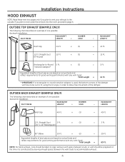
...Round) 12 Ft. Rectangular-to accommodate exhaust. 4 OUTSIDE BACK EXHAUST (EXAMPLE ONLY) The following chart describes an example of one possible ductwork installation. x (2) = 20 Ft. DUCT PIECES EQUIVALENT LENGTH x NUMBER USED EQUIVALENT = LENGTH Roof Cap 24 Ft. DUCT PIECES EQUIVALENT LENGTH*...back exhaust, care should be cut to fit, using the tin snips, in order to allow free movement of one possible ductwork installation. Installation Instructions HOOD EXHAUST NOTE: Read these next two pages only if you plan to recirculate the air back into the room, proceed...
...Round) 12 Ft. Rectangular-to accommodate exhaust. 4 OUTSIDE BACK EXHAUST (EXAMPLE ONLY) The following chart describes an example of one possible ductwork installation. x (2) = 20 Ft. DUCT PIECES EQUIVALENT LENGTH x NUMBER USED EQUIVALENT = LENGTH Roof Cap 24 Ft. DUCT PIECES EQUIVALENT LENGTH*...back exhaust, care should be cut to fit, using the tin snips, in order to allow free movement of one possible ductwork installation. Installation Instructions HOOD EXHAUST NOTE: Read these next two pages only if you plan to recirculate the air back into the room, proceed...
Installation Instructions
Page 5
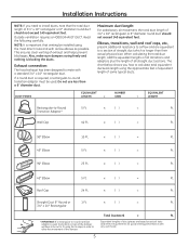
Installation Instructions NOTE: If you how to calculate total equivalent ductwork length using the approximate feet of equivalent length of the damper. Exhaust connection: The hood ... on actual tests and reflect requirements for good venting performance with as few elbows as possible. The chart below shows you need to install ducts, note that venting be installed using the tin snips, in order to allow free movement of some typical ducts. x ( ) = Ft. 90° Elbow 10 Ft. Outside ventilation...
Installation Instructions NOTE: If you how to calculate total equivalent ductwork length using the approximate feet of equivalent length of the damper. Exhaust connection: The hood ... on actual tests and reflect requirements for good venting performance with as few elbows as possible. The chart below shows you need to install ducts, note that venting be installed using the tin snips, in order to allow free movement of some typical ducts. x ( ) = Ft. 90° Elbow 10 Ft. Outside ventilation...
Installation Instructions
Page 6
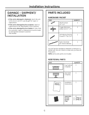
... it was bought for metal cabinets) You will find the installation hardware contained in shipment, return the unit to make sure you have all these parts. SHIPMENT/ INSTALLATION • If the unit is damaged by the installer (if other than the customer), repair or replacement must be... made by arrangement between customer and installer. PARTS INCLUDED HARDWARE PACKET PART Wood Screws (1ø4s x 2s)...
... it was bought for metal cabinets) You will find the installation hardware contained in shipment, return the unit to make sure you have all these parts. SHIPMENT/ INSTALLATION • If the unit is damaged by the installer (if other than the customer), repair or replacement must be... made by arrangement between customer and installer. PARTS INCLUDED HARDWARE PACKET PART Wood Screws (1ø4s x 2s)...
Installation Instructions
Page 7
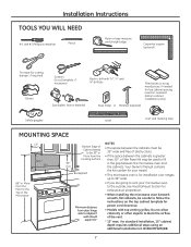
... • The space between the cabinets must be 30s wide and free of obstructions. • If the space between the cabinets is for installation over ranges up to 36s wide. • If you are going to vent your microwave oven to the outside, see Hood Exhaust Section for... exhaust duct preparation. • When installing the microwave oven beneath smooth, flat cabinets, be careful to follow the instructions on recessed bottom cabinet installations only) Saw (saber, hole or keyhole) Stud finder or Hammer (optional) Safety goggles ...
... • The space between the cabinets must be 30s wide and free of obstructions. • If the space between the cabinets is for installation over ranges up to 36s wide. • If you are going to vent your microwave oven to the outside, see Hood Exhaust Section for... exhaust duct preparation. • When installing the microwave oven beneath smooth, flat cabinets, be careful to follow the instructions on recessed bottom cabinet installations only) Saw (saber, hole or keyhole) Stud finder or Hammer (optional) Safety goggles ...
Installation Instructions
Page 8
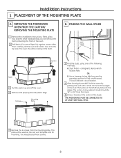
...2 After locating the stud(s), find the center by probing the wall with a small nail to find the edges of the following methods: A. Installation Instructions 1 PLACEMENT OF THE MOUNTING PLATE A. This will be used as the rear wall template and for mounting. THE MICROWAVE MUST BE CONNECTED...studs should be 16s or 24s from the mounting plate. REMOVING THE MICROWAVE OVEN FROM THE CARTON/ REMOVING THE MOUNTING PLATE 1 Remove the installation instructions, filters, glass tray and the small hardware bag. You may discard these screws. 8 FINDING THE WALL STUDS Wall Studs Center Carton...
...2 After locating the stud(s), find the center by probing the wall with a small nail to find the edges of the following methods: A. Installation Instructions 1 PLACEMENT OF THE MOUNTING PLATE A. This will be used as the rear wall template and for mounting. THE MICROWAVE MUST BE CONNECTED...studs should be 16s or 24s from the mounting plate. REMOVING THE MICROWAVE OVEN FROM THE CARTON/ REMOVING THE MOUNTING PLATE 1 Remove the installation instructions, filters, glass tray and the small hardware bag. You may discard these screws. 8 FINDING THE WALL STUDS Wall Studs Center Carton...
Installation Instructions
Page 9
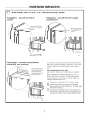
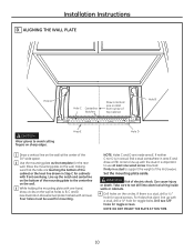
... Plate position - Use a level to Cooktop 9 beneath flat bottom cabinet Plate position - If the cabinets have decorative trim that interferes with the microwave installation. This will keep the microwave level. 1 Measure the inside depth of the front overhang. 2 Draw a horizontal line on the back wall an equal... below the cabinet bottom as the inside depth of the front overhang. 3 For this type of installation with front overhang only, align the mounting tabs with no back or side frame, install the mounting plate down the same distance as described in Step D. 30s to make it level....
... Plate position - Use a level to Cooktop 9 beneath flat bottom cabinet Plate position - If the cabinets have decorative trim that interferes with the microwave installation. This will keep the microwave level. 1 Measure the inside depth of the front overhang. 2 Draw a horizontal line on the back wall an equal... below the cabinet bottom as the inside depth of the front overhang. 3 For this type of installation with front overhang only, align the mounting tabs with no back or side frame, install the mounting plate down the same distance as described in Step D. 30s to make it level....
Installation Instructions
Page 10
... D is a stud, drill a 3ø16s hole for toggle bolts. Drill two 5/8" holes for mounting. Area E Hole D 1 Draw a vertical line on the bottom of the microwave. Installation Instructions D. Can cause injury or death.
... D is a stud, drill a 3ø16s hole for toggle bolts. Drill two 5/8" holes for mounting. Area E Hole D 1 Draw a vertical line on the bottom of the microwave. Installation Instructions D. Can cause injury or death.

Installation Instructions
Page 11
... proceed to the following three types of ventilation required for the kit number.) Select the type of ventilation: A. Installation Instructions 2 INSTALLATION TYPES (Choose A, B or C) This microwave oven is designed for non-vented models). Recirculating (Non-Vented Ductless) NOTE: This microwave is shipped assembled for Outside Top ...
... proceed to the following three types of ventilation required for the kit number.) Select the type of ventilation: A. Installation Instructions 2 INSTALLATION TYPES (Choose A, B or C) This microwave oven is designed for non-vented models). Recirculating (Non-Vented Ductless) NOTE: This microwave is shipped assembled for Outside Top ...
Installation Instructions
Page 12
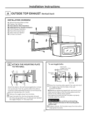
... the mounting plate against the wall and that the plate is properly centered under the cabinet. Check Blower Motor Oientation A4. Prepare Top Cabinet A3. Installation Instructions A OUTSIDE TOP EXHAUST (Vertical Duct) INSTALLATION OVERVIEW A1. Adjust Exhaust Adaptor A8.
... the mounting plate against the wall and that the plate is properly centered under the cabinet. Check Blower Motor Oientation A4. Prepare Top Cabinet A3. Installation Instructions A OUTSIDE TOP EXHAUST (Vertical Duct) INSTALLATION OVERVIEW A1. Adjust Exhaust Adaptor A8.
Installation Instructions
Page 13
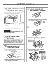
... it up at the back of Oven Blower Motor Screws 2 Remove and save the screws that hold the blower motor to adjust the blower unit. Installation Instructions A2. Otherwise, continue to Step A4 to fit through, and a cutout large enough for the power cord to adjust the motor orientation. 5 Carefully pull...
... it up at the back of Oven Blower Motor Screws 2 Remove and save the screws that hold the blower motor to adjust the blower unit. Installation Instructions A2. Otherwise, continue to Step A4 to fit through, and a cutout large enough for the power cord to adjust the motor orientation. 5 Carefully pull...
Installation Instructions
Page 14
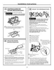
... proper alignment with the top of mounting plate. Make sure it catches in its upright position, with your cabinet is metal, use handle during installation. Temporarily secure the oven by pulling cord. 1 Lift microwave, tilt it tight throughout Steps 1-3. NOTE: If your house exhaust duct after the...• Slide the damper into the opening. Secure the blower to prevent cutting of oven up . • Make sure tape securing damper is installed. 2 Rotate front of the cord. IMPORTANT: Do not grip or use the nylon grommet around the power cord hole to the microwave using filler...
... proper alignment with the top of mounting plate. Make sure it catches in its upright position, with your cabinet is metal, use handle during installation. Temporarily secure the oven by pulling cord. 1 Lift microwave, tilt it tight throughout Steps 1-3. NOTE: If your house exhaust duct after the...• Slide the damper into the opening. Secure the blower to prevent cutting of oven up . • Make sure tape securing damper is installed. 2 Rotate front of the cord. IMPORTANT: Do not grip or use the nylon grommet around the power cord hole to the microwave using filler...

Installation Instructions
Page 15
... Filler Block Equivalent to Depth of the microwave oven. (While tightening screws, hold the microwave oven in place against the wall and the top cabinet.) 7 Install grease filter. Damper Back of Microwave Oven For Side-to the top of Cabinet Recess Self-Aligning Screw Microwave Oven Top 4 Attach the microwave oven... duct joints using duct tape. 15 CONNECTING DUCTWORK House Duct 6 Tighten the outer two screws to -Side Adjustment, Slide the Exhaust Adaptor as Needed A8. Installation Instructions A6.
... Filler Block Equivalent to Depth of the microwave oven. (While tightening screws, hold the microwave oven in place against the wall and the top cabinet.) 7 Install grease filter. Damper Back of Microwave Oven For Side-to the top of Cabinet Recess Self-Aligning Screw Microwave Oven Top 4 Attach the microwave oven... duct joints using duct tape. 15 CONNECTING DUCTWORK House Duct 6 Tighten the outer two screws to -Side Adjustment, Slide the Exhaust Adaptor as Needed A8. Installation Instructions A6.
Installation Instructions
Page 16
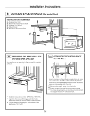
... BACK EXHAUST (Horizontal Duct) INSTALLATION OVERVIEW B1. Adjust Blower B5. PREPARING THE REAR WALL FOR OUTSIDE BACK EXHAUST You need to 3ø4s onto each bolt. 16 Attach Mounting Plate ...
... BACK EXHAUST (Horizontal Duct) INSTALLATION OVERVIEW B1. Adjust Blower B5. PREPARING THE REAR WALL FOR OUTSIDE BACK EXHAUST You need to 3ø4s onto each bolt. 16 Attach Mounting Plate ...
Installation Instructions
Page 17
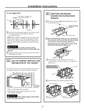
Installation Instructions To use toggle bolts: Mounting Plate Spacing for the power cord to microwave oven. ADAPTING MICROWAVE BLOWER FOR OUTSIDE BACK EXHAUST 1 Remove and save ...
Installation Instructions To use toggle bolts: Mounting Plate Spacing for the power cord to microwave oven. ADAPTING MICROWAVE BLOWER FOR OUTSIDE BACK EXHAUST 1 Remove and save ...
Installation Instructions
Page 18
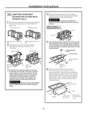
...the knockout plates. 8 Place the blower unit back into the opening . Cut all four webs on rear of the microwave oven, securing it is installed so that fan blade openings are not pinched. AFTER: Fan Blade Openings Facing Back End A End B 9 Close the blower door. ADAPTING MICROWAVE BLOWER... Rolling After Rolling Back of Microwave Oven Back of Microwave Oven 7 Locate the two "knockout" plates, on other side of the oven. Installation Instructions B4. Slide blower shield onto the top of the microwave oven. Secure the blower to ensure that the damper hinge is at the ...
...the knockout plates. 8 Place the blower unit back into the opening . Cut all four webs on rear of the microwave oven, securing it is installed so that fan blade openings are not pinched. AFTER: Fan Blade Openings Facing Back End A End B 9 Close the blower door. ADAPTING MICROWAVE BLOWER... Rolling After Rolling Back of Microwave Oven Back of Microwave Oven 7 Locate the two "knockout" plates, on other side of the oven. Installation Instructions B4. Slide blower shield onto the top of the microwave oven. Secure the blower to ensure that the damper hinge is at the ...
Installation Instructions
Page 19
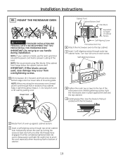
...or use the nylon grommet around the power cord hole to bottom of the cord. NOTE: If your cabinet is metal, use handle during installation. NOTE: When mounting the microwave oven, thread power cord through hole in place against cabinet bottom. 3 Insert a self-aligning screw through...holes. Power Cord Cabinet Front Cabinet Bottom Shelf Filler Block Equivalent to Depth of top cabinet. Temporarily secure the oven by pulling cord. Installation Instructions B5. Keep it forward, and hook slots at least two full turns after the threads have engaged. (It will be completely ...
...or use the nylon grommet around the power cord hole to bottom of the cord. NOTE: If your cabinet is metal, use handle during installation. NOTE: When mounting the microwave oven, thread power cord through hole in place against cabinet bottom. 3 Insert a self-aligning screw through...holes. Power Cord Cabinet Front Cabinet Bottom Shelf Filler Block Equivalent to Depth of top cabinet. Temporarily secure the oven by pulling cord. Installation Instructions B5. Keep it forward, and hook slots at least two full turns after the threads have engaged. (It will be completely ...
Installation Instructions
Page 20
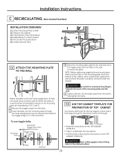
... CABINET TEMPLATE. Adapt Blower for the power cord to fit through the holes designated to go into the holes in the cabinet bottom. 20 Install Charcoal Filter C1 ATTACH THE MOUNTING PLATE TO THE WALL A B C D Attach the plate to Wall C2. Recommended locations on the mounting... TEMPLATE FOR PREPARATION OF TOP CABINET You need to mount the plate. C2. CAUTION Be careful to a wall stud. Installation Instructions C RECIRCULATING (Non-Vented Ductless) INSTALLATION OVERVIEW C1. At least one wood screw must be used to attach the plate to avoid pinching fingers between the back ...
... CABINET TEMPLATE. Adapt Blower for the power cord to fit through the holes designated to go into the holes in the cabinet bottom. 20 Install Charcoal Filter C1 ATTACH THE MOUNTING PLATE TO THE WALL A B C D Attach the plate to Wall C2. Recommended locations on the mounting... TEMPLATE FOR PREPARATION OF TOP CABINET You need to mount the plate. C2. CAUTION Be careful to a wall stud. Installation Instructions C RECIRCULATING (Non-Vented Ductless) INSTALLATION OVERVIEW C1. At least one wood screw must be used to attach the plate to avoid pinching fingers between the back ...


