
Quick Specs
Page 1
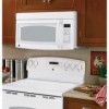
... website at ge.com or call GE Answer Center® service, 800.626.2000. Electrical receptacle must be used for adaptation to be located in cabinet above Spacemaker microwave oven. No additional wiring, venting or cabinet rebuilding necessary in inches) Note: Requires 120V grounded outlet. Complete detailed, easy-to-follow installation instructions and convenient...
... website at ge.com or call GE Answer Center® service, 800.626.2000. Electrical receptacle must be used for adaptation to be located in cabinet above Spacemaker microwave oven. No additional wiring, venting or cabinet rebuilding necessary in inches) Note: Requires 120V grounded outlet. Complete detailed, easy-to-follow installation instructions and convenient...
Installation Instructions
Page 1
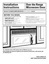
... instrucciones, visite nuestro sitio de internet ge.com. Keep these instructions for future reference. • Skill level - Save these instructions for local inspector's use. • IMPORTANT - READ CAREFULLY. KEEP THESE INSTRUCTIONS. Observe all governing codes and ordinances. • Note to Consumer - Installation of this manual, visit our Website at : ge.com BEFORE YOU BEGIN Read these...
... instrucciones, visite nuestro sitio de internet ge.com. Keep these instructions for future reference. • Skill level - Save these instructions for local inspector's use. • IMPORTANT - READ CAREFULLY. KEEP THESE INSTRUCTIONS. Observe all governing codes and ordinances. • Note to Consumer - Installation of this manual, visit our Website at : ge.com BEFORE YOU BEGIN Read these...
Installation Instructions
Page 2
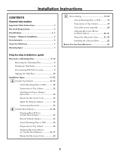
...Placement of Mounting Plate 8-10 Removing the Mounting Plate 8 Finding the Wall Studs 8 Determining Wall Plate Location 9 Aligning the Wall Plate 10 Installation Types 11-22 A Outside Top Exhaust 12-14 Attach Mounting Plate to Wall 12 Preparation of Top Cabinet 13 Checking for Proper Damper Operation... Plate to Wall 16 Preparation of Top Cabinet 16 Adapting Microwave Blower for Outside Back Exhaust 16, 17 Mount the Microwave Oven 18 2 Installation Instructions CONTENTS General information Important Safety Instructions 3 Electrical Requirements 3 Hood Exhaust 4, 5 Damage -
...Placement of Mounting Plate 8-10 Removing the Mounting Plate 8 Finding the Wall Studs 8 Determining Wall Plate Location 9 Aligning the Wall Plate 10 Installation Types 11-22 A Outside Top Exhaust 12-14 Attach Mounting Plate to Wall 12 Preparation of Top Cabinet 13 Checking for Proper Damper Operation... Plate to Wall 16 Preparation of Top Cabinet 16 Adapting Microwave Blower for Outside Back Exhaust 16, 17 Mount the Microwave Oven 18 2 Installation Instructions CONTENTS General information Important Safety Instructions 3 Electrical Requirements 3 Hood Exhaust 4, 5 Damage -
Installation Instructions
Page 3
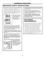
... personal safety, this appliance. CAUTION: For personal safety, remove house fuse or open circuit breaker before beginning installation to 20- You should be installed by a qualified electrician to minimize the possibility of electric shock hazard from this product cannot be capable of ...prong (grounding) wall receptacle to make sure the receptacle is 120 volts AC, 60 Hertz, 15 amps and 1.58 kilowatts. Installation Instructions IMPORTANT SAFETY INSTRUCTIONS This product requires a three-prong grounded outlet. DO NOT USE WITH AN EXTENSION CORD. Wire size must perform a ground ...
... personal safety, this appliance. CAUTION: For personal safety, remove house fuse or open circuit breaker before beginning installation to 20- You should be installed by a qualified electrician to minimize the possibility of electric shock hazard from this product cannot be capable of ...prong (grounding) wall receptacle to make sure the receptacle is 120 volts AC, 60 Hertz, 15 amps and 1.58 kilowatts. Installation Instructions IMPORTANT SAFETY INSTRUCTIONS This product requires a three-prong grounded outlet. DO NOT USE WITH AN EXTENSION CORD. Wire size must perform a ground ...
Installation Instructions
Page 4
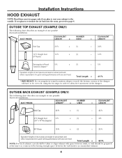
...performance with any vent hood. EQUIVALENT NUMBER EQUIVALENT DUCT PIECES LENGTH* x USED = LENGTH Wall Cap 40 Ft. Total Length = 63 Ft. Installation Instructions HOOD EXHAUST NOTE: Read these next two pages only if you plan to recirculate the air back into the room, proceed to page 6. ...-Round 5 Ft. x (2) = 20 Ft. OUTSIDE TOP EXHAUST (EXAMPLE ONLY) The following chart describes an example of one possible ductwork installation. x (1) = 12 Ft. OUTSIDE BACK EXHAUST (EXAMPLE ONLY) The following chart describes an example of one possible ductwork...
...performance with any vent hood. EQUIVALENT NUMBER EQUIVALENT DUCT PIECES LENGTH* x USED = LENGTH Wall Cap 40 Ft. Total Length = 63 Ft. Installation Instructions HOOD EXHAUST NOTE: Read these next two pages only if you plan to recirculate the air back into the room, proceed to page 6. ...-Round 5 Ft. x (2) = 20 Ft. OUTSIDE TOP EXHAUST (EXAMPLE ONLY) The following chart describes an example of one possible ductwork installation. x (1) = 12 Ft. OUTSIDE BACK EXHAUST (EXAMPLE ONLY) The following chart describes an example of one possible ductwork...

Installation Instructions
Page 5
...., present additional resistance to airflow and are based on actual tests and reflect requirements for good venting performance with any vent hood. Installation Instructions NOTE: If you how to -Round 5 Ft. Outside ventilation requires a HOOD EXHAUST DUCT. Maximum duct length: For satisfactory air...x ( ) = Ft. 25 Ft. x ( ) = Ft. 45° Elbow 5 Ft. x ( ) = Ft. Exhaust connection: The hood exhaust has been designed to install ducts, note that venting be cut to fit, using the most direct route and with as few elbows as possible. Transition Adaptor* Wall Cap 40...
...., present additional resistance to airflow and are based on actual tests and reflect requirements for good venting performance with any vent hood. Installation Instructions NOTE: If you how to -Round 5 Ft. Outside ventilation requires a HOOD EXHAUST DUCT. Maximum duct length: For satisfactory air...x ( ) = Ft. 25 Ft. x ( ) = Ft. 45° Elbow 5 Ft. x ( ) = Ft. Exhaust connection: The hood exhaust has been designed to install ducts, note that venting be cut to fit, using the most direct route and with as few elbows as possible. Transition Adaptor* Wall Cap 40...
Installation Instructions
Page 6
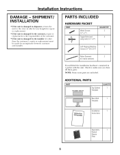
...metal cabinets) You will find the installation hardware contained in shipment, return the unit to make sure you have all these parts. ADDITIONAL PARTS PART Top Cabinet Template QUANTITY 1 Rear Wall 1 Template Installation 1 Instructions Separately 1 Packed Grease Filter 6 NOTE...: Some extra parts are included. SHIPMENT/ INSTALLATION • If the unit is damaged by the installer (if other than the customer), repair or replacement must...
...metal cabinets) You will find the installation hardware contained in shipment, return the unit to make sure you have all these parts. ADDITIONAL PARTS PART Top Cabinet Template QUANTITY 1 Rear Wall 1 Template Installation 1 Instructions Separately 1 Packed Grease Filter 6 NOTE...: Some extra parts are included. SHIPMENT/ INSTALLATION • If the unit is damaged by the installer (if other than the customer), repair or replacement must...
Installation Instructions
Page 7
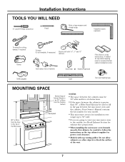
... number for your model. • This microwave oven is greater than 30″, a Filler Panel Kit may be used on recessed bottom cabinet installations only) Saw (saber, hole or keyhole) Stud finder or Hammer (optional) Safety goggles Level Duct and masking tape MOUNTING SPACE 161⁄2″... microwave oven beneath smooth, flat cabinets, be 30″ or More from the Cooking Surface 30″ min. Installation Instructions TOOLS YOU WILL NEED # 1 and #2 Phillips screwdriver Pencil Ruler or tape measure and straight edge Carpenter square (optional) Tin snips (for cutting ...
... number for your model. • This microwave oven is greater than 30″, a Filler Panel Kit may be used on recessed bottom cabinet installations only) Saw (saber, hole or keyhole) Stud finder or Hammer (optional) Safety goggles Level Duct and masking tape MOUNTING SPACE 161⁄2″... microwave oven beneath smooth, flat cabinets, be 30″ or More from the Cooking Surface 30″ min. Installation Instructions TOOLS YOU WILL NEED # 1 and #2 Phillips screwdriver Pencil Ruler or tape measure and straight edge Carpenter square (optional) Tin snips (for cutting ...
Installation Instructions
Page 8
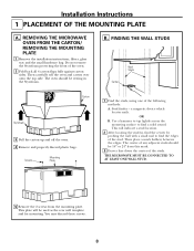
...mark halfway between the edges. You may discard these screws. 8 REMOVING THE MICROWAVE OVEN FROM THE CARTON/ REMOVING THE MOUNTING PLATE 1 Remove the installation instructions, filters, glass tray and the small hardware bag. The oven should be 16″ or 24″ from the mounting plate. OR B....BE CONNECTED TO AT LEAST ONE WALL STUD. 5 Remove the 2 screws from this mark. 3 Draw a line down the center of the studs. Installation Instructions 1 PLACEMENT OF THE MOUNTING PLATE A. This will be resting in the Styrofoam. This plate will indicate a stud location. 2 After locating the stud...
...mark halfway between the edges. You may discard these screws. 8 REMOVING THE MICROWAVE OVEN FROM THE CARTON/ REMOVING THE MOUNTING PLATE 1 Remove the installation instructions, filters, glass tray and the small hardware bag. The oven should be 16″ or 24″ from the mounting plate. OR B....BE CONNECTED TO AT LEAST ONE WALL STUD. 5 Remove the 2 screws from this mark. 3 Draw a line down the center of the studs. Installation Instructions 1 PLACEMENT OF THE MOUNTING PLATE A. This will be resting in the Styrofoam. This plate will indicate a stud location. 2 After locating the stud...
Installation Instructions
Page 9
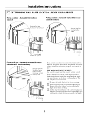
...30″, up to 36″ 30″ to make sure the cabinet bottom is level. Remove the decorative trim to install the microwave properly and to Cooktop Plate position - Use a level to Cooktop Your cabinets may have a front overhang only, with... trim that interferes with the microwave installation. DETERMINING WALL PLATE LOCATION UNDER YOUR CABINET Plate position - beneath recessed bottom cabinet with front overhang Mounting Plate with Tabs Below Cabinet Bottom the Same Distance as the front overhang depth. Installation Instructions C. beneath flat bottom cabinet Plate ...
...30″, up to 36″ 30″ to make sure the cabinet bottom is level. Remove the decorative trim to install the microwave properly and to Cooktop Plate position - Use a level to Cooktop Your cabinets may have a front overhang only, with... trim that interferes with the microwave installation. DETERMINING WALL PLATE LOCATION UNDER YOUR CABINET Plate position - beneath recessed bottom cabinet with front overhang Mounting Plate with Tabs Below Cabinet Bottom the Same Distance as the front overhang depth. Installation Instructions C. beneath flat bottom cabinet Plate ...
Installation Instructions
Page 10
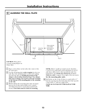
.../actual plate marked with a stud, drill a 5⁄8″ hole for the rear wall. If neither C nor D is a stud, drill a 3⁄16″ hole for mounting. Installation Instructions D.
.../actual plate marked with a stud, drill a 5⁄8″ hole for the rear wall. If neither C nor D is a stud, drill a 3⁄16″ hole for mounting. Installation Instructions D.
Installation Instructions
Page 11
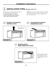
... Top Exhaust (Vertical Duct) B. Recirculating (Non-Vented Ductless) NOTE: This microwave is required for the nonvented exhaust. (See your installation and proceed to the following three types of ventilation required for your Owner's Manual for the kit number.) Installation Instructions 2 INSTALLATION TYPES (Choose A, B or C) This microwave oven is designed for adaptation to that section.
... Top Exhaust (Vertical Duct) B. Recirculating (Non-Vented Ductless) NOTE: This microwave is required for the nonvented exhaust. (See your installation and proceed to the following three types of ventilation required for your Owner's Manual for the kit number.) Installation Instructions 2 INSTALLATION TYPES (Choose A, B or C) This microwave oven is designed for adaptation to that section.
Installation Instructions
Page 12
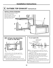
... THE WALL To use toggle bolts: Mounting Plate Spacing for Toggles More Than Wall Thickness Toggle Wings Toggle Bolt Attach the plate to Wall A2. Installation Instructions A OUTSIDE TOP EXHAUST (Vertical Duct...
... THE WALL To use toggle bolts: Mounting Plate Spacing for Toggles More Than Wall Thickness Toggle Wings Toggle Bolt Attach the plate to Wall A2. Installation Instructions A OUTSIDE TOP EXHAUST (Vertical Duct...
Installation Instructions
Page 13
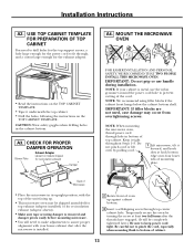
...bottom edge onto four lower tabs of top cabinet. CAUTION: Wear safety goggles when drilling holes in its upright position, with your cabinet is installed. 2 Rotate front of cabinet. 13 NOTE: When mounting the microwave oven, thread power cord through , and a cutout large enough for ... the TOP CABINET TEMPLATE. • Tape it underneath the top cabinet. • Drill the holes, following the instructions on the TOP CABINET TEMPLATE. Installation Instructions A2. Temporarily secure the oven by pulling cord. 1 Lift microwave, tilt it tight throughout Steps 1-3. NOTE: If your ...
...bottom edge onto four lower tabs of top cabinet. CAUTION: Wear safety goggles when drilling holes in its upright position, with your cabinet is installed. 2 Rotate front of cabinet. 13 NOTE: When mounting the microwave oven, thread power cord through , and a cutout large enough for ... the TOP CABINET TEMPLATE. • Tape it underneath the top cabinet. • Drill the holes, following the instructions on the TOP CABINET TEMPLATE. Installation Instructions A2. Temporarily secure the oven by pulling cord. 1 Lift microwave, tilt it tight throughout Steps 1-3. NOTE: If your ...
Installation Instructions
Page 14
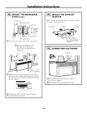
... the exhaust adaptor to connect to the top cabinet. 5 Insert 2 self-aligning screws through outer top cabinet holes. Turn two full turns on each screw. Installation Instructions A4. MOUNT THE MICROWAVE OVEN (cont.) Cabinet Front Cabinet Bottom Shelf Filler Block Equivalent to Depth of Microwave For Front-to-Back or Side-to...
... the exhaust adaptor to connect to the top cabinet. 5 Insert 2 self-aligning screws through outer top cabinet holes. Turn two full turns on each screw. Installation Instructions A4. MOUNT THE MICROWAVE OVEN (cont.) Cabinet Front Cabinet Bottom Shelf Filler Block Equivalent to Depth of Microwave For Front-to-Back or Side-to...
Installation Instructions
Page 15
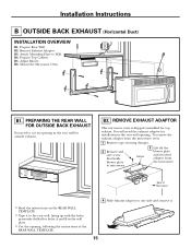
... WALL FOR OUTSIDE BACK EXHAUST You need the exhaust adaptor for installation in the rear wall opening , following the instructions of Microwave • Read the instructions on the REAR WALL TEMPLATE. • Tape it . 15 To remove the exhaust adaptor from the microwave. Installation Instructions B OUTSIDE BACK EXHAUST (Horizontal Duct) INSTALLATION OVERVIEW B1. Adjust Blower B6.
... WALL FOR OUTSIDE BACK EXHAUST You need the exhaust adaptor for installation in the rear wall opening , following the instructions of Microwave • Read the instructions on the REAR WALL TEMPLATE. • Tape it . 15 To remove the exhaust adaptor from the microwave. Installation Instructions B OUTSIDE BACK EXHAUST (Horizontal Duct) INSTALLATION OVERVIEW B1. Adjust Blower B6.
Installation Instructions
Page 16
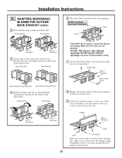
... the TOP CABINET TEMPLATE. ADAPTING MICROWAVE BLOWER FOR OUTSIDE BACK EXHAUST 1 Remove and save screw that the plate is properly centered under the cabinet. Installation Instructions B3. Attach the plate to avoid pinching fingers between the back of Microwave Blower Motor Screw 2 Carefully pull out the blower unit. Blower Motor Back ...
... the TOP CABINET TEMPLATE. ADAPTING MICROWAVE BLOWER FOR OUTSIDE BACK EXHAUST 1 Remove and save screw that the plate is properly centered under the cabinet. Installation Instructions B3. Attach the plate to avoid pinching fingers between the back of Microwave Blower Motor Screw 2 Carefully pull out the blower unit. Blower Motor Back ...
Installation Instructions
Page 17
Installation Instructions B5. AFTER: Fan Blade Openings Facing Back End A End B Back of Microwave Back of the blower unit. Before Rolling After Rolling CAUTION: Do not pull ... back of microwave oven. 7 Secure the blower unit to the microwave with the screw. 9 Attach the exhaust adaptor to assure that the damper hinge is installed so that it into the opening. Reroute the wires through grooves on rear of the oven. Take care to the rear of the oven by...
Installation Instructions B5. AFTER: Fan Blade Openings Facing Back End A End B Back of Microwave Back of the blower unit. Before Rolling After Rolling CAUTION: Do not pull ... back of microwave oven. 7 Secure the blower unit to the microwave with the screw. 9 Attach the exhaust adaptor to assure that the damper hinge is installed so that it into the opening. Reroute the wires through grooves on rear of the oven. Take care to the rear of the oven by...
Installation Instructions
Page 18
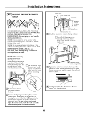
... 5 Insert 2 self-aligning screws through hole in place against the wall and the top cabinet.) 2 Rotate front of cabinet. 8 Install grease filter. NOTE: We recommend using filler blocks if the cabinet front hangs below the cabinet bottom shelf. IMPORTANT: If filler blocks are...NOTE: If your cabinet is metal, use handle during installation. See the Owner's Manual packed with the microwave. 18 Installation Instructions B6. MOUNT THE MICROWAVE OVEN FOR EASIER INSTALLATION AND PERSONAL SAFETY, WE RECOMMEND THAT TWO PEOPLE INSTALL THIS MICROWAVE OVEN. Do not pinch cord or lift oven...
... 5 Insert 2 self-aligning screws through hole in place against the wall and the top cabinet.) 2 Rotate front of cabinet. 8 Install grease filter. NOTE: We recommend using filler blocks if the cabinet front hangs below the cabinet bottom shelf. IMPORTANT: If filler blocks are...NOTE: If your cabinet is metal, use handle during installation. See the Owner's Manual packed with the microwave. 18 Installation Instructions B6. MOUNT THE MICROWAVE OVEN FOR EASIER INSTALLATION AND PERSONAL SAFETY, WE RECOMMEND THAT TWO PEOPLE INSTALL THIS MICROWAVE OVEN. Do not pinch cord or lift oven...

Installation Instructions
Page 19
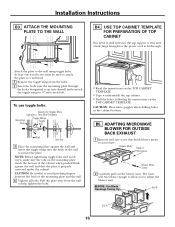
... Spacing for the power cord to fit through the holes designated to go into the holes in the cabinet bottom. 19 Installation Instructions C RECIRCULATING (Non-Vented Ductless) INSTALLATION OVERVIEW C1. ATTACH THE MOUNTING PLATE TO THE WALL 3 Place the mounting plate against the wall and that the plate ...NOTE: Before tightening toggle bolts and wood screw, make sure the tabs on the TOP CABINET TEMPLATE. Attach the plate to Wall C2. Install Charcoal Filter C1. Attach Mounting Plate to the wall using toggle bolts. CAUTION: Wear safety goggles when drilling holes in the wall to...
... Spacing for the power cord to fit through the holes designated to go into the holes in the cabinet bottom. 19 Installation Instructions C RECIRCULATING (Non-Vented Ductless) INSTALLATION OVERVIEW C1. ATTACH THE MOUNTING PLATE TO THE WALL 3 Place the mounting plate against the wall and that the plate ...NOTE: Before tightening toggle bolts and wood screw, make sure the tabs on the TOP CABINET TEMPLATE. Attach the plate to Wall C2. Install Charcoal Filter C1. Attach Mounting Plate to the wall using toggle bolts. CAUTION: Wear safety goggles when drilling holes in the wall to...

