
Owners Manual
Page 1
... notre site web à l'adresse www.electromenagersge.ca As an ENERGY STAR® partner, GE has determined that this manual, visit our Website at ge.com. TINSEA518JBRZ 49-7572 03-07 JR Air ConditionRoeorms ge.com Owner's Manual and Installation Instructions Safety Instructions 2, 3 Operating Instructions Controls-Control Knobs . . . . 8, 9 Controls-Touch Pads 4-6 Care and Cleaning...
... notre site web à l'adresse www.electromenagersge.ca As an ENERGY STAR® partner, GE has determined that this manual, visit our Website at ge.com. TINSEA518JBRZ 49-7572 03-07 JR Air ConditionRoeorms ge.com Owner's Manual and Installation Instructions Safety Instructions 2, 3 Operating Instructions Controls-Control Knobs . . . . 8, 9 Controls-Touch Pads 4-6 Care and Cleaning...
Owners Manual
Page 2
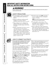
...house wiring circuits which mates with a new power supply cord obtained from the power cord. Consumer Support Troubleshooting Tips Installation Instructions Care and Cleaning Operating Instructions Safety Instructions IMPORTANT SAFETY INFORMATION. SAFETY PRECAUTIONS I This air conditioner must be ...service technician. I Never unplug your personal responsibility and obligation to do not store or use of this appliance must be properly installed in this appliance. Where a 2-prong wall outlet is encountered, it is properly grounded. WARNING! I For your safety, ...
...house wiring circuits which mates with a new power supply cord obtained from the power cord. Consumer Support Troubleshooting Tips Installation Instructions Care and Cleaning Operating Instructions Safety Instructions IMPORTANT SAFETY INFORMATION. SAFETY PRECAUTIONS I This air conditioner must be ...service technician. I Never unplug your personal responsibility and obligation to do not store or use of this appliance must be properly installed in this appliance. Where a 2-prong wall outlet is encountered, it is properly grounded. WARNING! I For your safety, ...
Owners Manual
Page 3
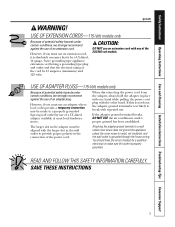
... slot in the wall outlet to provide proper polarity in the adapter must use of the power cord. Safety Instructions Operating Instructions Care and Cleaning Installation Instructions Troubleshooting Tips Consumer Support ge.com WARNING!
... slot in the wall outlet to provide proper polarity in the adapter must use of the power cord. Safety Instructions Operating Instructions Care and Cleaning Installation Instructions Troubleshooting Tips Consumer Support ge.com WARNING!
Owners Manual
Page 4
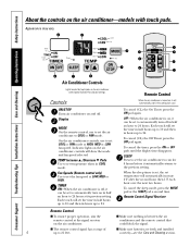
... conditioner is off, it automatically returns to 21 feet. SLEEP Press to automatically turn off . I Make sure batteries are fresh and installed 4 up to 24 hours. Consumer Support Troubleshooting Tips Installation Instructions Care and Cleaning Operating Instructions Safety Instructions About the controls on and off in COOL mode. When the sleep timer...
... conditioner is off, it automatically returns to 21 feet. SLEEP Press to automatically turn off . I Make sure batteries are fresh and installed 4 up to 24 hours. Consumer Support Troubleshooting Tips Installation Instructions Care and Cleaning Operating Instructions Safety Instructions About the controls on and off in COOL mode. When the sleep timer...

Owners Manual
Page 5
... or HI pads to 85°F in the CONT setting. To open or close the vent: 1. Safety Instructions Operating Instructions Care and Cleaning Installation Instructions Troubleshooting Tips Consumer Support ge.com COOL MODE Remote Control 1. Control Panel 1. Press the INCREASE L / DECREASE M pads to set the desired temperature 60°F to set temperature...
... or HI pads to 85°F in the CONT setting. To open or close the vent: 1. Safety Instructions Operating Instructions Care and Cleaning Installation Instructions Troubleshooting Tips Consumer Support ge.com COOL MODE Remote Control 1. Control Panel 1. Press the INCREASE L / DECREASE M pads to set the desired temperature 60°F to set temperature...

Owners Manual
Page 6
Temperature Limiting To reach the auxiliary controls remove the front grille. Limit 3 - Auxiliary Controls - Consumer Support Troubleshooting Tips Installation Instructions Care and Cleaning Operating Instructions Safety Instructions About the controls on the air conditioner-models with touch pads. Temperature limiting can be set for ...
Temperature Limiting To reach the auxiliary controls remove the front grille. Limit 3 - Auxiliary Controls - Consumer Support Troubleshooting Tips Installation Instructions Care and Cleaning Operating Instructions Safety Instructions About the controls on the air conditioner-models with touch pads. Temperature limiting can be set for ...
Owners Manual
Page 7
Safety Instructions Operating Instructions Care and Cleaning Installation Instructions Troubleshooting Tips Consumer Support 7 ge.com Notes.
Safety Instructions Operating Instructions Care and Cleaning Installation Instructions Troubleshooting Tips Consumer Support 7 ge.com Notes.
Owners Manual
Page 8
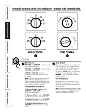
.... A 3-minute delay is used to provide full heat capability. For Maximum Heating-Select HIGH HEAT with the thermostat at maximum heat. Consumer Support Troubleshooting Tips Installation Instructions Care and Cleaning Operating Instructions Safety Instructions WARM About the controls on the air conditioner-models with control knobs. NOTE: If you turn the...
.... A 3-minute delay is used to provide full heat capability. For Maximum Heating-Select HIGH HEAT with the thermostat at maximum heat. Consumer Support Troubleshooting Tips Installation Instructions Care and Cleaning Operating Instructions Safety Instructions WARM About the controls on the air conditioner-models with control knobs. NOTE: If you turn the...

Owners Manual
Page 9
...card, turn it over and replace it by the use of the temp control is located behind the control panel. When set at front. ge.com or (Depending on the front of the air discharge area. The unit leaves the factory set at CLOSE, only the air inside the... hole in card over locating pin inside air is shipped in holes accessed through the control box. Safety Instructions Operating Instructions Care and Cleaning Installation Instructions Troubleshooting Tips Consumer Support Fan Switch To reach the fan switch(es) remove the front grille. The unit is exhausted outside. Remove ...
...card, turn it over and replace it by the use of the temp control is located behind the control panel. When set at front. ge.com or (Depending on the front of the air discharge area. The unit leaves the factory set at CLOSE, only the air inside the... hole in card over locating pin inside air is shipped in holes accessed through the control box. Safety Instructions Operating Instructions Care and Cleaning Installation Instructions Troubleshooting Tips Consumer Support Fan Switch To reach the fan switch(es) remove the front grille. The unit is exhausted outside. Remove ...
Owners Manual
Page 10
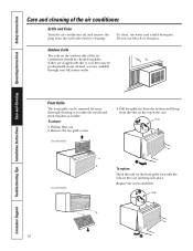
... Coils The coils on the front grille even with dirt or soot they may be professionally steam cleaned, a service available through your GE service outlet. To remove: 1. Remove the two grille screws. Pull the grille out from the bottom and lift up from the wall...of the air conditioner should be removed for more thorough cleaning or to make the model and serial numbers accessible. Consumer Support Troubleshooting Tips Installation Instructions Care and Cleaning Operating Instructions Safety Instructions Care and cleaning of the case. Do not use water and a mild detergent. Replace ...
... Coils The coils on the front grille even with dirt or soot they may be professionally steam cleaned, a service available through your GE service outlet. To remove: 1. Remove the two grille screws. Pull the grille out from the bottom and lift up from the wall...of the air conditioner should be removed for more thorough cleaning or to make the model and serial numbers accessible. Consumer Support Troubleshooting Tips Installation Instructions Care and Cleaning Operating Instructions Safety Instructions Care and cleaning of the case. Do not use water and a mild detergent. Replace ...
Owners Manual
Page 11
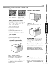
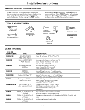
...Pull it should be used for a long time. 11 Replacement filters are installed correctly. 3 Reattach the cover by pushing it back into position. I Remove the batteries from your salesperson, GE dealer, GE Service and Parts Center or authorized Customer Care® servicers. To replace the... I Use 2 AAA (1.5 volt) batteries. NOTES: I Vacuum off before replacing. Safety Instructions Operating Instructions Care and Cleaning Installation Instructions Troubleshooting Tips Consumer Support To maintain optimum performance, clean the filter at least every 30 days.
...Pull it should be used for a long time. 11 Replacement filters are installed correctly. 3 Reattach the cover by pushing it back into position. I Remove the batteries from your salesperson, GE dealer, GE Service and Parts Center or authorized Customer Care® servicers. To replace the... I Use 2 AAA (1.5 volt) batteries. NOTES: I Vacuum off before replacing. Safety Instructions Operating Instructions Care and Cleaning Installation Instructions Troubleshooting Tips Consumer Support To maintain optimum performance, clean the filter at least every 30 days.
Owners Manual
Page 12
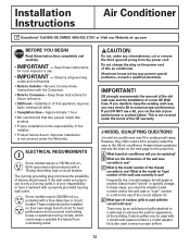
... protected with a 15-amp time delay fuse or circuit breaker. GE strongly recommends the removal of the old wall case and the installation of electric shock hazard. A What brand air conditioner will apply to improper installation is used to prevent overloading house or apartment wiring circuits, which ...these cases, you run the risk of the wall case currently in existing wall cases. Installation of the correct adapter kit. The 3-prong grounding plug minimizes the possibility of a new GE Wall Case. These models should be replacing? However, they often need the chassis model ...
... protected with a 15-amp time delay fuse or circuit breaker. GE strongly recommends the removal of the old wall case and the installation of electric shock hazard. A What brand air conditioner will apply to improper installation is used to prevent overloading house or apartment wiring circuits, which ...these cases, you run the risk of the wall case currently in existing wall cases. Installation of the correct adapter kit. The 3-prong grounding plug minimizes the possibility of a new GE Wall Case. These models should be replacing? However, they often need the chassis model ...
Owners Manual
Page 13
...257⁄8″W x 157⁄16″H x 16″D Standard wall case for all GE wall cases 26″W x 18″H x 24″D Adapts an older Hotpoint wall case to a "J" model chassis. Installation Instructions Read these kits for "J" model chassis. Fits Hotpoint wall cases 253⁄4″W x ... pressing the TEST button and then the RESET button. Fits Whirlpool wall cases 257⁄8″W x 161⁄2″H x 231⁄8″D Adapts GE wall case to ensure proper airflow. Fits the RAB 30 wall case 26″W x 18″H x 24″D Adapts Fedders wall case to ...
...257⁄8″W x 157⁄16″H x 16″D Standard wall case for all GE wall cases 26″W x 18″H x 24″D Adapts an older Hotpoint wall case to a "J" model chassis. Installation Instructions Read these kits for "J" model chassis. Fits Hotpoint wall cases 253⁄4″W x ... pressing the TEST button and then the RESET button. Fits Whirlpool wall cases 257⁄8″W x 161⁄2″H x 231⁄8″D Adapts GE wall case to ensure proper airflow. Fits the RAB 30 wall case 26″W x 18″H x 24″D Adapts Fedders wall case to ...
Owners Manual
Page 14
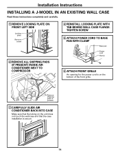
...3 CAREFULLY SLIDE AIR CONDITIONER BACK INTO CASE Make sure that the tubing on the unit does not touch the wall case and that the case installation is on the bottom of the front grille. TIGHTEN SCREW 5 ATTACH POWER CORD TO BASE PAN WITH CLAMP Base pan Power cord Clamp 6 ...ATTACH FRONT GRILLE An opening for the power cord is secure. 14 Installation Instructions INSTALLING A J-MODEL IN AN EXISTING WALL CASE Read these instructions completely and carefully. 1 REMOVE LOCKING PLATE ON FRONT LEFT SIDE Locking plate Remove screw 2...
...3 CAREFULLY SLIDE AIR CONDITIONER BACK INTO CASE Make sure that the tubing on the unit does not touch the wall case and that the case installation is on the bottom of the front grille. TIGHTEN SCREW 5 ATTACH POWER CORD TO BASE PAN WITH CLAMP Base pan Power cord Clamp 6 ...ATTACH FRONT GRILLE An opening for the power cord is secure. 14 Installation Instructions INSTALLING A J-MODEL IN AN EXISTING WALL CASE Read these instructions completely and carefully. 1 REMOVE LOCKING PLATE ON FRONT LEFT SIDE Locking plate Remove screw 2...
Owners Manual
Page 15
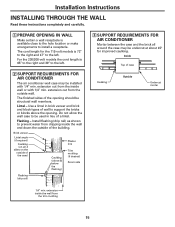
...wall and down the outside of case Caulking Outside Undercut mortar 1/4″ min. extension out from the outside of wall to the left . Install flashing (drip rail) as shown to be used in brick veneer and brick and block types of the case) Caulking (above the opening... may be undercut at about 45° for the 115-volt models is 72″ to the right and 47″ to install a receptacle. Installation Instructions INSTALLING THROUGH THE WALL Read these instructions completely and carefully. 1 PREPARE OPENING IN WALL Make certain a wall receptacle is available close to ...
...wall and down the outside of case Caulking Outside Undercut mortar 1/4″ min. extension out from the outside of wall to the left . Install flashing (drip rail) as shown to be used in brick veneer and brick and block types of the case) Caulking (above the opening... may be undercut at about 45° for the 115-volt models is 72″ to the right and 47″ to install a receptacle. Installation Instructions INSTALLING THROUGH THE WALL Read these instructions completely and carefully. 1 PREPARE OPENING IN WALL Make certain a wall receptacle is available close to ...
Owners Manual
Page 16
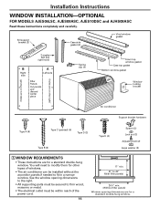
... window opening dimensions to the right. • All supporting parts must be secured to firm wood, masonry or metal. • The electrical outlet must be installed without the accordion panels if needed to 43″ (With filler panels) 261⁄4″ min. (Without filler panels) Window opening dimensions are for a standard...
... window opening dimensions to the right. • All supporting parts must be secured to firm wood, masonry or metal. • The electrical outlet must be installed without the accordion panels if needed to 43″ (With filler panels) 261⁄4″ min. (Without filler panels) Window opening dimensions are for a standard...

Owners Manual
Page 17
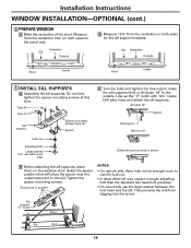
Installation Instructions 2 STORM WINDOW REQUIREMENTS A storm window frame will not allow removal of the case use the 2 short screws. To adjust for this, attach a piece of ... pads (if present) inside the window frame. If attaching the grille on the grille until it fits flush with nails or screws provided by the installer. 3 REMOVE AIR CONDITIONER FROM CASE A Remove the front grille. See the Care and Cleaning section. Remove shipping pads (if present) G Remove the rear grille that...
Installation Instructions 2 STORM WINDOW REQUIREMENTS A storm window frame will not allow removal of the case use the 2 short screws. To adjust for this, attach a piece of ... pads (if present) inside the window frame. If attaching the grille on the grille until it fits flush with nails or screws provided by the installer. 3 REMOVE AIR CONDITIONER FROM CASE A Remove the front grille. See the Care and Cleaning section. Remove shipping pads (if present) G Remove the rear grille that...
Owners Manual
Page 18
Drill pilot holes and attach the sill supports. Sill Centerline Outside Stool 123⁄8″ 123⁄8″ Inside 5 INSTALL SILL SUPPORTS A Assemble the sill supports. Line up the "V" notch with wood sills) Offset sill (such as brick or stone) B ... the sill support brackets. Sill support "V" notch Stool Sill Bolt 18 Do not fully tighten the spacer mounting screws at this time. Installation Instructions WINDOW INSTALLATION-OPTIONAL (cont.) 4 PREPARE WINDOW A Mark the centerline of the stool. Average sill Spacer Sill support Narrow sill Lock nut Adjusting bolt...
Drill pilot holes and attach the sill supports. Sill Centerline Outside Stool 123⁄8″ 123⁄8″ Inside 5 INSTALL SILL SUPPORTS A Assemble the sill supports. Line up the "V" notch with wood sills) Offset sill (such as brick or stone) B ... the sill support brackets. Sill support "V" notch Stool Sill Bolt 18 Do not fully tighten the spacer mounting screws at this time. Installation Instructions WINDOW INSTALLATION-OPTIONAL (cont.) 4 PREPARE WINDOW A Mark the centerline of the stool. Average sill Spacer Sill support Narrow sill Lock nut Adjusting bolt...
Owners Manual
Page 19
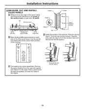
... clips 3″ from the top and the bottom. B A Right Left side side Gasket Angle Angle Gasket Panel Tab Type C (painted screws) D Install the panels in the window. Hook the tab into the sill support. 3″ (holes are on the left) (holes are on each side of the... B Mark the A and B measurements on the right) Filler Panels Cut panels and discard center piece C Put together the panel assemblies. Installation Instructions 6 MEASURE, CUT AND INSTALL FILLER PANELS A Measure from the edge of the panel marks (see Prepare the Window) to locate the holes in the angles. Cut the...
... clips 3″ from the top and the bottom. B A Right Left side side Gasket Angle Angle Gasket Panel Tab Type C (painted screws) D Install the panels in the window. Hook the tab into the sill support. 3″ (holes are on the left) (holes are on each side of the... B Mark the A and B measurements on the right) Filler Panels Cut panels and discard center piece C Put together the panel assemblies. Installation Instructions 6 MEASURE, CUT AND INSTALL FILLER PANELS A Measure from the edge of the panel marks (see Prepare the Window) to locate the holes in the angles. Cut the...

Owners Manual
Page 20
... side. Panel tabs Case screws Panel tab Vinyl window gasket I Close the window tightly on the stool and over the case top gasket. Installation Instructions WINDOW INSTALLATION-OPTIONAL (cont.) 7 INSTALL CASE IN WINDOW A Peel off the backing from the bottom window gasket. Bend the gasket forward to the case, open the window, and...
... side. Panel tabs Case screws Panel tab Vinyl window gasket I Close the window tightly on the stool and over the case top gasket. Installation Instructions WINDOW INSTALLATION-OPTIONAL (cont.) 7 INSTALL CASE IN WINDOW A Peel off the backing from the bottom window gasket. Bend the gasket forward to the case, open the window, and...


