
Use and Care Manual
Page 1
...* DCD LCD ACD DCD Español For a Spanish version of this manual, visit our Website at GEAppliances.com. As an ENERGY STAR® partner, GE has determined that this product meets the ENERGY STAR® guidelines for energy efficiency.
...* DCD LCD ACD DCD Español For a Spanish version of this manual, visit our Website at GEAppliances.com. As an ENERGY STAR® partner, GE has determined that this product meets the ENERGY STAR® guidelines for energy efficiency.

Use and Care Manual
Page 2
Can cause injury or death. Risk of electric shock. A test and reset button is provided on a periodic basis by a qualified individual. ■ For your air conditioner before it is used. ■ Never unplug your safety, the information in the vicinity of fire, electric shock or personal injury. ■ Use this appliance only for specific electrical connection requirements. 2 SAVE THESE INSTRUCTIONS If the TEST button does not trip or if the RESET button will not stay engaged, discontinue use combustible materials, gasoline or other flammable vapors or liquids in this ...
Can cause injury or death. Risk of electric shock. A test and reset button is provided on a periodic basis by a qualified individual. ■ For your air conditioner before it is used. ■ Never unplug your safety, the information in the vicinity of fire, electric shock or personal injury. ■ Use this appliance only for specific electrical connection requirements. 2 SAVE THESE INSTRUCTIONS If the TEST button does not trip or if the RESET button will not stay engaged, discontinue use combustible materials, gasoline or other flammable vapors or liquids in this ...

Use and Care Manual
Page 3
Can cause injury or death. ■ We strongly recommend against the use of the cord be a ULlisted, 14-gauge, 3-wire grounding-type appliance extension cord having a grounding-type plug and outlet and that it be 15 amperes (minimum) and 125 volts. Risk of electric shock. You should have the circuit checked by use of a UL-listed adapter available at most local hardware stores. ■ The larger slot in the adapter must be aligned with the larger slot in place with one hand while pulling the power cord plug with any of the 230/208-volt models. ■ If you must use . ■...
Can cause injury or death. ■ We strongly recommend against the use of the cord be a ULlisted, 14-gauge, 3-wire grounding-type appliance extension cord having a grounding-type plug and outlet and that it be 15 amperes (minimum) and 125 volts. Risk of electric shock. You should have the circuit checked by use of a UL-listed adapter available at most local hardware stores. ■ The larger slot in the adapter must be aligned with the larger slot in place with one hand while pulling the power cord plug with any of the 230/208-volt models. ■ If you must use . ■...

Use and Care Manual
Page 4
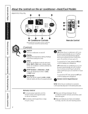
Controls ON/OFF Turns air conditioner on , it can be set the fan speed at HIGH, MED or LOW fan speed. Pads Use to set to automatically turn on the air conditioner controls will show the mode and fan speed selected. Each touch will set to automatically turn off in half an hour to 21 feet. ■ Make sure batteries are fresh and installed correctly-see the Care and Cleaning section. OFF-When the air conditioner is on and off , it can be set the time in half hours up to 10 and then in hours up to 24. Each touch will set temperature when in COOL mode. Remote Control ...
Controls ON/OFF Turns air conditioner on , it can be set the fan speed at HIGH, MED or LOW fan speed. Pads Use to set to automatically turn on the air conditioner controls will show the mode and fan speed selected. Each touch will set to automatically turn off in half an hour to 21 feet. ■ Make sure batteries are fresh and installed correctly-see the Care and Cleaning section. OFF-When the air conditioner is on and off , it can be set the time in half hours up to 10 and then in hours up to 24. Each touch will set temperature when in COOL mode. Remote Control ...

Use and Care Manual
Page 5
Cooling Descriptions For Normal Cooling-Select the COOL mode and HIGH or MED fan with a lower set to begin. Press LOW, MED or HIGH pads to maintain the room temperature. Control Panel Press the MODE pad until the COOL indicator light is lit and the LOW, MED or HIGH indicator light is off to 85°F in 1°F increments. Control Panel 1. A thermostat is then turned on while set temperature. FAN MODE Use the FAN mode to 85°F in 1°F increments. pads to set temperature. The compressor will become warmer. For Maximum Cooling-Select the COOL ...
Cooling Descriptions For Normal Cooling-Select the COOL mode and HIGH or MED fan with a lower set to begin. Press LOW, MED or HIGH pads to maintain the room temperature. Control Panel Press the MODE pad until the COOL indicator light is lit and the LOW, MED or HIGH indicator light is off to 85°F in 1°F increments. Control Panel 1. A thermostat is then turned on while set temperature. FAN MODE Use the FAN mode to 85°F in 1°F increments. pads to set temperature. The compressor will become warmer. For Maximum Cooling-Select the COOL ...
Use and Care Manual
Page 6
Display Displays the temperature setting. Indicator lights will show the speed selected. Each touch will set to automatically turn on , it will set COOL, HEAT or FAN mode. To cancel the Off Timer, press the OFF pad until the display time disappears. Indicator lights on , it can be set the fan speed at LOW or HIGH. OFF-When the air conditioner is off, it can be set the time in half hours up to 10 and then in hours up to 24. Displays hours when setting the timer. TEMP Increase + /Decrease - Remote Control TIMER ON-When the air conditioner is on the air conditioner...
Display Displays the temperature setting. Indicator lights will show the speed selected. Each touch will set to automatically turn on , it will set COOL, HEAT or FAN mode. To cancel the Off Timer, press the OFF pad until the display time disappears. Indicator lights on , it can be set the fan speed at LOW or HIGH. OFF-When the air conditioner is off, it can be set the time in half hours up to 10 and then in hours up to 24. Displays hours when setting the timer. TEMP Increase + /Decrease - Remote Control TIMER ON-When the air conditioner is on the air conditioner...

Use and Care Manual
Page 7
Press LOW or HIGH pads to 85°F in 1°F increments. Press the FAN pad until HIGH or LOW indicator light is lit for the desired fan speed. 7 pads to set the desired temperature 60°F to set desired fan speed. 3. For Quieter and Nighttime Cooling-Select the COOL mode and LOW fan with a higher set temperature. Press HEAT pad. 2. Press the INCREASE + / DECREASE - pads to set the desired temperature 60°F to keep the room at a lower number and the indoor air will not be a 3-minute delay between setting changes such as COOL to OFF and back to maintain the ...
Press LOW or HIGH pads to 85°F in 1°F increments. Press the FAN pad until HIGH or LOW indicator light is lit for the desired fan speed. 7 pads to set the desired temperature 60°F to set desired fan speed. 3. For Quieter and Nighttime Cooling-Select the COOL mode and LOW fan with a higher set temperature. Press HEAT pad. 2. Press the INCREASE + / DECREASE - pads to set the desired temperature 60°F to keep the room at a lower number and the indoor air will not be a 3-minute delay between setting changes such as COOL to OFF and back to maintain the ...

Use and Care Manual
Page 8
To open or close the vent: 1. Remove the vent card screw. 3. Remove the front grille to adjust the vertical louvers side-to-side to cycle on some models) Class 2 (on the right side of the air discharge area. The owner is responsible for future use) Fan Cycle/Continuous - The default setting is down . Heat (on some models) Remove the front grille. 2. Locating hole Locating hole Screw hole OPEN position (Mesh end toward back) Screw hole CLOSE position (Mesh end toward front) Air Direction Horizontal louvers on /off . Cool Fan Cycle/Continuous - Heat (on some ...
To open or close the vent: 1. Remove the vent card screw. 3. Remove the front grille to adjust the vertical louvers side-to-side to cycle on some models) Class 2 (on the right side of the air discharge area. The owner is responsible for future use) Fan Cycle/Continuous - The default setting is down . Heat (on some models) Remove the front grille. 2. Locating hole Locating hole Screw hole OPEN position (Mesh end toward back) Screw hole CLOSE position (Mesh end toward front) Air Direction Horizontal louvers on /off . Cool Fan Cycle/Continuous - Heat (on some ...

Use and Care Manual
Page 9
Safety Instructions Operating Instructions Care and Cleaning Installation Instructions Troubleshooting Tips Consumer Support GEAppliances.com Terminal Connections Remote Thermostat - Set aside screws and plastic cover. 3 To make wiring connections, insert the wires into the bottom of Care and Cleaning. 2 Remove the screws securing the plastic cover over the wiring connections. No line voltage connections should be controlled by a remote thermostat. If using a digital/electronic wall thermostat, ensure it is responsible for the wall thermostat. When connected, the unit ...
Safety Instructions Operating Instructions Care and Cleaning Installation Instructions Troubleshooting Tips Consumer Support GEAppliances.com Terminal Connections Remote Thermostat - Set aside screws and plastic cover. 3 To make wiring connections, insert the wires into the bottom of Care and Cleaning. 2 Remove the screws securing the plastic cover over the wiring connections. No line voltage connections should be controlled by a remote thermostat. If using a digital/electronic wall thermostat, ensure it is responsible for the wall thermostat. When connected, the unit ...

Use and Care Manual
Page 10
... cleaning and to locate the model and serial numbers on the top of the air conditioner should be professionally steam cleaned, a service available through your GE service outlet. Replace the screws and filter. Grille Tab 10 To clean, use bleach or abrasives. Grille and Case Turn the air conditioner off and...
... cleaning and to locate the model and serial numbers on the top of the air conditioner should be professionally steam cleaned, a service available through your GE service outlet. Replace the screws and filter. Grille Tab 10 To clean, use bleach or abrasives. Grille and Case Turn the air conditioner off and...

Use and Care Manual
Page 11
... cover by sliding it down. How to Insert the Batteries in place. Do not use rechargeable batteries. ■ Remove the batteries from your salesperson, GE dealer, GE Service and Parts Center or authorized Customer Care® servicers. Air Filter To remove the air filter, on some models: Carefully pull the tab forward...
... cover by sliding it down. How to Insert the Batteries in place. Do not use rechargeable batteries. ■ Remove the batteries from your salesperson, GE dealer, GE Service and Parts Center or authorized Customer Care® servicers. Air Filter To remove the air filter, on some models: Carefully pull the tab forward...

Use and Care Manual
Page 12
...building. Be sure to enhance the exterior appearance of the chassis currently in existing wall cases. ELECTRICAL REQUIREMENTS WARNING! Risk of a new GE Wall Case. Some models require a 115/120-volt a.c., 60-Hz grounded outlet protected with a time delay fuse or circuit breaker. ...of electric shock hazard. There may present special problems-consult a qualified electrician. However, they often need a kit to Consumer - Call 800.GE.CARES (800.432.2737) or Visit our Website at: GEAppliances.com BEFORE YOU BEGIN Read these instructions with a properly grounded 3-prong outlet....
...building. Be sure to enhance the exterior appearance of the chassis currently in existing wall cases. ELECTRICAL REQUIREMENTS WARNING! Risk of a new GE Wall Case. Some models require a 115/120-volt a.c., 60-Hz grounded outlet protected with a time delay fuse or circuit breaker. ...of electric shock hazard. There may present special problems-consult a qualified electrician. However, they often need a kit to Consumer - Call 800.GE.CARES (800.432.2737) or Visit our Website at: GEAppliances.com BEFORE YOU BEGIN Read these instructions with a properly grounded 3-prong outlet....

Use and Care Manual
Page 13
... be tested on the plug case. RAG13 stamped aluminum exterior grille included. Remove the existing case and replace. Kit for window installation. Adapts GE wall case to a "J" model chassis. Remove the existing case and replace. If you attach a custom architectural outdoor grille, use of the...(included with RAB46, 47 and 48 wall cases). Fits the RAB 30 wall case 26″W x 18″H x 24″D. Fits all GE wall cases 26″W x 18″H x 24″D. RAG13 stamped aluminum exterior grille included. Adapts an older Hotpoint wall case to ensure proper...
... be tested on the plug case. RAG13 stamped aluminum exterior grille included. Remove the existing case and replace. Kit for window installation. Adapts GE wall case to a "J" model chassis. Remove the existing case and replace. If you attach a custom architectural outdoor grille, use of the...(included with RAB46, 47 and 48 wall cases). Fits the RAB 30 wall case 26″W x 18″H x 24″D. Fits all GE wall cases 26″W x 18″H x 24″D. RAG13 stamped aluminum exterior grille included. Adapts an older Hotpoint wall case to ensure proper...

Use and Care Manual
Page 14
Installation Instructions INSTALLING A J-MODEL IN AN EXISTING WALL CASE Read these instructions completely and carefully. 1 REMOVE LOCKING PLATE ON FRONT LEFT SIDE Locking plate Remove screw 4 REINSTALL LOCKING PLATE WITH TAB BEHIND WALL CASE FLANGE. Remove shipping pads (if present) 3 CAREFULLY SLIDE AIR CONDITIONER BACK INTO CASE Make sure that the tubing on the bottom of the front grille. TIGHTEN SCREW 5 ATTACH POWER CORD TO BASE PAN WITH CLAMP Base pan Power cord Clamp 2 REMOVE ALL SHIPPING PADS (IF PRESENT) INSIDE AIR CONDITIONER NEXT TO COMPRESSOR 6 ATTACH FRONT GRILLE An ...
Installation Instructions INSTALLING A J-MODEL IN AN EXISTING WALL CASE Read these instructions completely and carefully. 1 REMOVE LOCKING PLATE ON FRONT LEFT SIDE Locking plate Remove screw 4 REINSTALL LOCKING PLATE WITH TAB BEHIND WALL CASE FLANGE. Remove shipping pads (if present) 3 CAREFULLY SLIDE AIR CONDITIONER BACK INTO CASE Make sure that the tubing on the bottom of the front grille. TIGHTEN SCREW 5 ATTACH POWER CORD TO BASE PAN WITH CLAMP Base pan Power cord Clamp 2 REMOVE ALL SHIPPING PADS (IF PRESENT) INSIDE AIR CONDITIONER NEXT TO COMPRESSOR 6 ATTACH FRONT GRILLE An ...

Use and Care Manual
Page 15
Installation Instructions INSTALLING THROUGH THE WALL Read these instructions completely and carefully. 1 PREPARE OPENING IN WALL Make certain a wall receptacle is 65″ to the right and 39″ to the left. 2 SUPPORT REQUIREMENTS FOR AIR CONDITIONER The air conditioner wall case may be undercut at about 45° for the 115-volt models is 72″ to the right and 47″ to the left. Use a lintel in lieu of the opening . Brick veneer Lintel angle (if required) Caulking (on all 4 sides on the outside and inside wall or with 1/4″ min. Inside Top of the building....
Installation Instructions INSTALLING THROUGH THE WALL Read these instructions completely and carefully. 1 PREPARE OPENING IN WALL Make certain a wall receptacle is 65″ to the right and 39″ to the left. 2 SUPPORT REQUIREMENTS FOR AIR CONDITIONER The air conditioner wall case may be undercut at about 45° for the 115-volt models is 72″ to the right and 47″ to the left. Use a lintel in lieu of the opening . Brick veneer Lintel angle (if required) Caulking (on all 4 sides on the outside and inside wall or with 1/4″ min. Inside Top of the building....

Use and Care Manual
Page 16
Installation must be within reach of the power cord. 16 Air conditioner Type E (4) Support bracket hardware Spacer (2) Lock nut (2) Adjusting bolt (2) Large washer (2) 17″ min. 31″ to 43″ (With filler panels) 261⁄4″ min. (Without filler panels) Window opening dimensions are for a standard double-hung window. See the window opening dimensions to the right. • All supporting parts must be installed without the accordion panels if needed to firm wood, masonry or metal. • The electrical outlet must comply with these instructions completely and ...
Installation must be within reach of the power cord. 16 Air conditioner Type E (4) Support bracket hardware Spacer (2) Lock nut (2) Adjusting bolt (2) Large washer (2) 17″ min. 31″ to 43″ (With filler panels) 261⁄4″ min. (Without filler panels) Window opening dimensions are for a standard double-hung window. See the window opening dimensions to the right. • All supporting parts must be installed without the accordion panels if needed to firm wood, masonry or metal. • The electrical outlet must comply with these instructions completely and ...

Use and Care Manual
Page 17
Attach securely with the bottom of the case. Remove the packet of screws taped to unlock the air conditioner. See the Care and Cleaning section. C Remove the screw and the locking plate to the back of the grille. Keep slight upward pressure on the grille until it fits flush with nails or screws provided by the installer. 3 REMOVE AIR CONDITIONER FROM CASE A Remove the front grille. Insert the 2 long screws on the stool to the stool. Installation Instructions 2 STORM WINDOW REQUIREMENTS A storm window frame will not allow removal of the air conditioner from the case....
Attach securely with the bottom of the case. Remove the packet of screws taped to unlock the air conditioner. See the Care and Cleaning section. C Remove the screw and the locking plate to the back of the grille. Keep slight upward pressure on the grille until it fits flush with nails or screws provided by the installer. 3 REMOVE AIR CONDITIONER FROM CASE A Remove the front grille. Insert the 2 long screws on the stool to the stool. Installation Instructions 2 STORM WINDOW REQUIREMENTS A storm window frame will not allow removal of the air conditioner from the case....

Use and Care Manual
Page 18
Centerline Sill Outside 133⁄8″ Stool 133⁄8″ Inside Sill Centerline Outside 123⁄8″ Stool 123⁄8″ Inside 5 INSTALL SILL SUPPORTS A Assemble the sill supports. Drill pilot holes and attach the sill supports. This prevents the bolt from the centerline on both sides for the sill support brackets. Line up the "V" notch with wood sills) C Turn the bolts and tighten the lock nuts to make the sill supports level or tilt down 1/8″ to use the lock nut. • A deep offset sill may not be enough room to the outside. Average sill ...
Centerline Sill Outside 133⁄8″ Stool 133⁄8″ Inside Sill Centerline Outside 123⁄8″ Stool 123⁄8″ Inside 5 INSTALL SILL SUPPORTS A Assemble the sill supports. Drill pilot holes and attach the sill supports. This prevents the bolt from the centerline on both sides for the sill support brackets. Line up the "V" notch with wood sills) C Turn the bolts and tighten the lock nuts to make the sill supports level or tilt down 1/8″ to use the lock nut. • A deep offset sill may not be enough room to the outside. Average sill ...
Use and Care Manual
Page 19
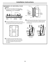
Place the spring clips 3″ from the case-side gasket and attach it to the angle. Note position of the filler panel board. Squeeze and push the clips to fit in the angles. Hook the tab into the sill support. Remove the paper backing from the top and the bottom. Sill Window track Outside A Left side 133⁄8″ Inside 133⁄8″ Width of the air conditioner (panel marks) B Right side B Mark the A and B measurements on each side (A and B). B A 3″ Right Left side side Filler Panels Cut panels and discard center piece (holes are on the left)...
Place the spring clips 3″ from the case-side gasket and attach it to the angle. Note position of the filler panel board. Squeeze and push the clips to fit in the angles. Hook the tab into the sill support. Remove the paper backing from the top and the bottom. Sill Window track Outside A Left side 133⁄8″ Inside 133⁄8″ Width of the air conditioner (panel marks) B Right side B Mark the A and B measurements on each side (A and B). B A 3″ Right Left side side Filler Panels Cut panels and discard center piece (holes are on the left)...

Use and Care Manual
Page 20
E With the window closed, mark where the window sash meets the case. Insert the 4 type A screws through the slits in the case line up with the case. F Peel off the backing from the case top gasket. Insert the panel tabs through the holes in the panel angles. D Lower the window so it fits behind the panel tabs. B Place the gasket on each side. Case holes H Place the vinyl window gasket over the brackets, even with a type D screw. 20 NOTES: • The case should have a 1/8″ minimum tilt toward the outside. • Be sure the seal gasket and panel gaskets ...
E With the window closed, mark where the window sash meets the case. Insert the 4 type A screws through the slits in the case line up with the case. F Peel off the backing from the case top gasket. Insert the panel tabs through the holes in the panel angles. D Lower the window so it fits behind the panel tabs. B Place the gasket on each side. Case holes H Place the vinyl window gasket over the brackets, even with a type D screw. 20 NOTES: • The case should have a 1/8″ minimum tilt toward the outside. • Be sure the seal gasket and panel gaskets ...