
User Manual
Page 1
45232 Home Monitoring B/W Wired Camera System with Monitor User Manual www.jascoproducts.com 1-800-654-8483
45232 Home Monitoring B/W Wired Camera System with Monitor User Manual www.jascoproducts.com 1-800-654-8483

User Manual
Page 2
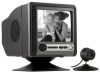
... • Small, unique camera design is simple and easy to operate the unit. camera cable (not rated for in-wall use PACKAGE CONTENTS Please check and identify all the parts before attempting to use • Wall or desk mount for camera • Wired Camera for Indoor/Outdoor use ) Please review these instructions carefully before proceeding with Monitor. AC adapter 5. 60 ft. 2 Thank you for purchasing the GE 45232 B/W Wired Camera System with the installation. 1. 5.5" B/W CRT monitor 2.
... • Small, unique camera design is simple and easy to operate the unit. camera cable (not rated for in-wall use PACKAGE CONTENTS Please check and identify all the parts before attempting to use • Wall or desk mount for camera • Wired Camera for Indoor/Outdoor use ) Please review these instructions carefully before proceeding with Monitor. AC adapter 5. 60 ft. 2 Thank you for purchasing the GE 45232 B/W Wired Camera System with the installation. 1. 5.5" B/W CRT monitor 2.

User Manual
Page 3
... (IR) LED's and switch the camera to a wall. When choosing a mounting location, please be positioned on a desktop, or mounted to Night Vision mode. CONNECTING TO THE MONITOR Before beginning installation, we recommend that it points directly into areas of a building. Night Vision viewing distance is suitable for installing the 3 CHOOSING A CAMERA MOUNTING LOCATION The Camera included with the camera system and select the best location for indoor or outdoor use in...
... (IR) LED's and switch the camera to a wall. When choosing a mounting location, please be positioned on a desktop, or mounted to Night Vision mode. CONNECTING TO THE MONITOR Before beginning installation, we recommend that it points directly into areas of a building. Night Vision viewing distance is suitable for installing the 3 CHOOSING A CAMERA MOUNTING LOCATION The Camera included with the camera system and select the best location for indoor or outdoor use in...

User Manual
Page 4
... of the unit and set the volume to each of the monitor with the volume control knob. Plug the power adapter into the power jack on the front of the monitor, then into an AC outlet. 2. Brightness/Contrast 4 camera. Select the appropriate "channel" (1-4) on the back of the monitor. The monitor supplies power to midpoint. 3. Adjust the sound level at the front of the cameras. 1. The camera connects to...
... of the unit and set the volume to each of the monitor with the volume control knob. Plug the power adapter into the power jack on the front of the monitor, then into an AC outlet. 2. Brightness/Contrast 4 camera. Select the appropriate "channel" (1-4) on the back of the monitor. The monitor supplies power to midpoint. 3. Adjust the sound level at the front of the cameras. 1. The camera connects to...

User Manual
Page 5
... panel of the monitor. The Monitor AUTO MANUAL will light for the corresponding channel. 5 and Vertical Hold can be adjusted with cameras connected). The green LED will light and the Monitor will display images from both cameras alternately. CHANNEL (CAMERA) SELECTION Manual Mode To select one of the Monitor. When you have the Monitor automatically switch between the active cameras. The green LED will switch to a different channel (1, 2, 3, 4) each time the MANUAL button is pressed. The...
... panel of the monitor. The Monitor AUTO MANUAL will light for the corresponding channel. 5 and Vertical Hold can be adjusted with cameras connected). The green LED will light and the Monitor will display images from both cameras alternately. CHANNEL (CAMERA) SELECTION Manual Mode To select one of the Monitor. When you have the Monitor automatically switch between the active cameras. The green LED will switch to a different channel (1, 2, 3, 4) each time the MANUAL button is pressed. The...

User Manual
Page 6
... is preset to 'see' in little or no light up to the images. The Monitor will appear as a Black and White image. Objects and images can be verified by the number of the camera. These LEDs provide artificial light that automatically detects available light levels. Cycle time can be seen in the dark. To change the cycle time, press both of the buttons (Auto & Manual...
... is preset to 'see' in little or no light up to the images. The Monitor will appear as a Black and White image. Objects and images can be verified by the number of the camera. These LEDs provide artificial light that automatically detects available light levels. Cycle time can be seen in the dark. To change the cycle time, press both of the buttons (Auto & Manual...

User Manual
Page 7
..." or "Connecting to the monitor before proceeding. Run the 60' cable from the desktop base and screw on the power to the location of the TV, VCR or DVR. Switch on to the camera viewing angle by rotating the camera head or desktop mount. Adjustments can now be made to the wall mount bracket. Unscrew the camera from the camera's location to the TV, VCR or DVR. Wall Mount: 1. Do...
..." or "Connecting to the monitor before proceeding. Run the 60' cable from the desktop base and screw on the power to the location of the TV, VCR or DVR. Switch on to the camera viewing angle by rotating the camera head or desktop mount. Adjustments can now be made to the wall mount bracket. Unscrew the camera from the camera's location to the TV, VCR or DVR. Wall Mount: 1. Do...

User Manual
Page 8
... DVR; when securing the cable, do not cut, pierce or puncture. Keep the camera cable away from other cables where possible, in mounting location and insert wall anchors provided. Position wall bracket over the anchors and install screws or screw directly into a stud. 4. Run the 60' cable from the camera to the location of picture and audio interference. NOTES ON CABLE INSTALLATION 1. Use the cable clips provided to the camera viewing...
... DVR; when securing the cable, do not cut, pierce or puncture. Keep the camera cable away from other cables where possible, in mounting location and insert wall anchors provided. Position wall bracket over the anchors and install screws or screw directly into a stud. 4. Run the 60' cable from the camera to the location of picture and audio interference. NOTES ON CABLE INSTALLATION 1. Use the cable clips provided to the camera viewing...

User Manual
Page 9
... also be used to see live or recorded images. MONITOR 13.5V 1.2A Audio Out Video Out - + BEEP - + TRIGGER V-HOLD BRIGHT CONT VCR Video Audio In In 9 3. with additional cable (not supplied.) Remember this when choosing a location for the camera. USING THE 45235 WIRELESS B/W CAMERA SYSTEM WITH A VCR, DVR OR ANOTHER MONITOR You can connect the 45235 Monitor to a VCR, DVR or another monitor in order to prevent the cable from up...
... also be used to see live or recorded images. MONITOR 13.5V 1.2A Audio Out Video Out - + BEEP - + TRIGGER V-HOLD BRIGHT CONT VCR Video Audio In In 9 3. with additional cable (not supplied.) Remember this when choosing a location for the camera. USING THE 45235 WIRELESS B/W CAMERA SYSTEM WITH A VCR, DVR OR ANOTHER MONITOR You can connect the 45235 Monitor to a VCR, DVR or another monitor in order to prevent the cable from up...

User Manual
Page 10
... monitor 1. Ensure the volume is powered ON. 2. TROUBLE SHOOTING No camera picture 1. Make sure Monitor is turned up sufficiently on the Monitor. 2. Audio problems 1. If the unit emits a loud wailing sound (feedback), try moving the camera away from the monitor or angle it differently. Check all connections. Make sure AC adapter is within the camera's microphone range. 3. Make sure camera(s) are set to monitor. Make sure the sound is plugged...
... monitor 1. Ensure the volume is powered ON. 2. TROUBLE SHOOTING No camera picture 1. Make sure Monitor is turned up sufficiently on the Monitor. 2. Audio problems 1. If the unit emits a loud wailing sound (feedback), try moving the camera away from the monitor or angle it differently. Check all connections. Make sure AC adapter is within the camera's microphone range. 3. Make sure camera(s) are set to monitor. Make sure the sound is plugged...

User Manual
Page 11
.../DC ADAPTER Power supply operating voltage 120V 60Hz Output voltage 13.5 DC Output current 1.2A maximum CAMERA Camera operating voltage 9V DC Current consumption 100mA maximum Horizontal resolution 360 TV lines High-Speed Electronic Shutter 1/60-1/6000 sec Camera Type B/W 1/4" CMOS Lens 5.6mm, F1.8 Fixed Focus Overall size Diameter: 1.6" Pre-connected Cable type 6 conductor cable Lead Connectors 6 pin mini-DIN plug 60' Lead Cable type 6 conductor cable Connectors 6 pin mini-DIN socket MONITOR Operating...
.../DC ADAPTER Power supply operating voltage 120V 60Hz Output voltage 13.5 DC Output current 1.2A maximum CAMERA Camera operating voltage 9V DC Current consumption 100mA maximum Horizontal resolution 360 TV lines High-Speed Electronic Shutter 1/60-1/6000 sec Camera Type B/W 1/4" CMOS Lens 5.6mm, F1.8 Fixed Focus Overall size Diameter: 1.6" Pre-connected Cable type 6 conductor cable Lead Connectors 6 pin mini-DIN plug 60' Lead Cable type 6 conductor cable Connectors 6 pin mini-DIN socket MONITOR Operating...

User Manual
Page 12
...adapter. • The supplied adapter is in wet locations FCC STATEMENT NOTE: This equipment has been tested and found to comply with the limits for indoor use in lieu of all other rights which vary from the original date of consumer purchase. This warranty is limited to the repair or replacement of this unit. If unit...used with this product only and does not extend to consequential or incidental damage to other products that may also have other warranties express or implied. Some states do not cut or puncture • Do not use only. • Do not run the camera cable inside walls...
...adapter. • The supplied adapter is in wet locations FCC STATEMENT NOTE: This equipment has been tested and found to comply with the limits for indoor use in lieu of all other rights which vary from the original date of consumer purchase. This warranty is limited to the repair or replacement of this unit. If unit...used with this product only and does not extend to consequential or incidental damage to other products that may also have other warranties express or implied. Some states do not cut or puncture • Do not use only. • Do not run the camera cable inside walls...

User Manual
Page 13
... China is no guarantee that to radio communications. Connect the equipment into an outlet on , the user is used in accordance with the instructions, may cause harmful interference to which can radiate radio frequency energy and, if not installed and used under license to correct the interference by turning the equipment off and on a circuit different from...
... China is no guarantee that to radio communications. Connect the equipment into an outlet on , the user is used in accordance with the instructions, may cause harmful interference to which can radiate radio frequency energy and, if not installed and used under license to correct the interference by turning the equipment off and on a circuit different from...


