Canadian COM Radio Installation & Operation Limitations
Page 1
... Pilot's Guide SL30 NAV/COM Installation Manual SL40 VHF/COM Pilot's Guide SL40 VHF/COM Transceiver Installation Manual SL40 Mobile Supplemental User's Guide SL40 Mobile Installation Manual SL40 Base Station Supplemental User's Guide SL40 Base Station Installation Manual SL50 GPS Receiver and SL60 GPS Receiver/VHF/COM SL50 GPS and SL60 GPS/VHF/COM Installation Manual GX User's Guide, Models...
... Pilot's Guide SL30 NAV/COM Installation Manual SL40 VHF/COM Pilot's Guide SL40 VHF/COM Transceiver Installation Manual SL40 Mobile Supplemental User's Guide SL40 Mobile Installation Manual SL40 Base Station Supplemental User's Guide SL40 Base Station Installation Manual SL50 GPS Receiver and SL60 GPS Receiver/VHF/COM SL50 GPS and SL60 GPS/VHF/COM Installation Manual GX User's Guide, Models...
SL 40 User Guide
Page 3
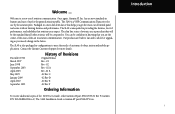
... also packaged in knowing that aviation users expect. The SL40 is a VHF Communications Transceiver for use for upgrading as your needs change in the future. The SL40 is unequaled in features and ease of the SL40 User's Guide, order Garmin AT part #560-0954-02 Rev F (Garmin P/N 190-00488-00 Rev A). You can be compared to...
... also packaged in knowing that aviation users expect. The SL40 is a VHF Communications Transceiver for use for upgrading as your needs change in the future. The SL40 is unequaled in features and ease of the SL40 User's Guide, order Garmin AT part #560-0954-02 Rev F (Garmin P/N 190-00488-00 Rev A). You can be compared to...
SL 40 User Guide
Page 7
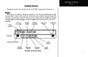
A photocell is composed of the front panel display. Getting Started Display SL40 Display and Control Description 1 Getting Started This guide describes the operation of the display from low brightness at night to high brightness during daylight operation. The photocell automatically controls the intensity of the SL40 VHF Communication Transceiver. Display The 1-line by 16-character display is located in the top left corner of 5x7 dot matrix alphanumeric high intensity LEDs. Brightness levels may also be controlled manually.
A photocell is composed of the front panel display. Getting Started Display SL40 Display and Control Description 1 Getting Started This guide describes the operation of the display from low brightness at night to high brightness during daylight operation. The photocell automatically controls the intensity of the SL40 VHF Communication Transceiver. Display The 1-line by 16-character display is located in the top left corner of 5x7 dot matrix alphanumeric high intensity LEDs. Brightness levels may also be controlled manually.
SL 40 User Guide
Page 10
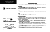
... are displayed to the right of the decimal point. Turn the Small, inner knob to change the values in 25 kHz increments. The SL40 may be installed to be disabled. Turn the Large and Small knobs clockwise to increase and counterclockwise to disable automatic squelch. Turn the Large....50 s119.80 Toggle Standby and Active frequencies with the Flip/Flop button 4 Detailed Operation This section introduces the basic operating details of the SL40 to select the desired frequency. 1. While viewing the frequency display, use the Large and Small knobs on /off control will be powered from...
... are displayed to the right of the decimal point. Turn the Small, inner knob to change the values in 25 kHz increments. The SL40 may be installed to be disabled. Turn the Large and Small knobs clockwise to increase and counterclockwise to disable automatic squelch. Turn the Large....50 s119.80 Toggle Standby and Active frequencies with the Flip/Flop button 4 Detailed Operation This section introduces the basic operating details of the SL40 to select the desired frequency. 1. While viewing the frequency display, use the Large and Small knobs on /off control will be powered from...