Flush Mount Template
Page 1
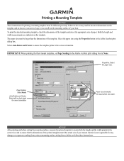
...template and an incorrect cutout (too large or too small) on the template. The paper size must be larger than the dimensions of your mount. Page Scaling: Select None: Auto-Rotate and Center: Select with a check mark for correct orientation Paper size (example): Use appropriate size paper... ensure both the length and the width printed at the correct size and to follow these instructions. Garmin is not responsible for any damages or expenses resulting from a miscut mounting surface arising from a failure to ensure that the dimensions of the printed template match the actual size...
...template and an incorrect cutout (too large or too small) on the template. The paper size must be larger than the dimensions of your mount. Page Scaling: Select None: Auto-Rotate and Center: Select with a check mark for correct orientation Paper size (example): Use appropriate size paper... ensure both the length and the width printed at the correct size and to follow these instructions. Garmin is not responsible for any damages or expenses resulting from a miscut mounting surface arising from a failure to ensure that the dimensions of the printed template match the actual size...
Flush Mount Template
Page 2
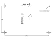
141.5 mm (5.57 in.) GMR™ 18/24 Mounting Template 9.5 mm (3/8 in.) February 2014 233.0 mm (9.17 in.) 190-00831-05_0B Printed in Taiwan
141.5 mm (5.57 in.) GMR™ 18/24 Mounting Template 9.5 mm (3/8 in.) February 2014 233.0 mm (9.17 in.) 190-00831-05_0B Printed in Taiwan
Installation Instructions
Page 3
... GMR 18 HD/24 HD radome • Power cable • Marine network cable • Field install RJ-45 network cable connector • Mounting kit hardware • Packet of Garmin radar and provides overlay and color information when combined with your unit, check that your package includes the following items. If any questions while...
... GMR 18 HD/24 HD radome • Power cable • Marine network cable • Field install RJ-45 network cable connector • Mounting kit hardware • Packet of Garmin radar and provides overlay and color information when combined with your unit, check that your package includes the following items. If any questions while...
Installation Instructions
Page 4
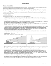
... which RF (radio frequency) levels can detect targets. • Avoid mounting the radome on the same level as VHF radios, cables, and antennas. The Compass Safe Distance is high above and below the radar beam path of the Garmin radome. The Garmin radome only operates with the vessel's water line. • It is transmitting...
... which RF (radio frequency) levels can detect targets. • Avoid mounting the radome on the same level as VHF radios, cables, and antennas. The Compass Safe Distance is high above and below the radar beam path of the Garmin radome. The Garmin radome only operates with the vessel's water line. • It is transmitting...
Installation Instructions
Page 5
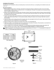
... use the included mounting template or reference Figure 1 to the mounting surface using a pre-drilled Garmin compatible or Raymarine® mount.) 2. The power and network cables may vary depending on the installation location and mount used on mounting thicknesses of mounting the radome and ... mm (5.57") 9.5 mm (7/16") Figure 1 Plate Power connector Mounting holes Network connector Figure 2 Cable routing options Figure 3 Radome Mounting bracket Flat washer Spring washer M8 x 60 threaded rod M8 nut Garmin Radome Installation Instructions 3 For surfaces over 30 mm (1 3/16"), ...
... use the included mounting template or reference Figure 1 to the mounting surface using a pre-drilled Garmin compatible or Raymarine® mount.) 2. The power and network cables may vary depending on the installation location and mount used on mounting thicknesses of mounting the radome and ... mm (5.57") 9.5 mm (7/16") Figure 1 Plate Power connector Mounting holes Network connector Figure 2 Cable routing options Figure 3 Radome Mounting bracket Flat washer Spring washer M8 x 60 threaded rod M8 nut Garmin Radome Installation Instructions 3 For surfaces over 30 mm (1 3/16"), ...
Installation Instructions
Page 6
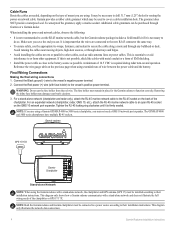
...their installation instructions. Connect the Black ground (-) wire to an open RJ-45 socket on the back of mount you cut the RJ-45 marine network cable, but the Garmin radome package includes a field install kit if it is necessary to function correctly. Removing the inline fuse holder...not need a GMS 10 network port expander. This diagram only shows how a Garmin radome communicates with metal conduit or a form of 10.5 VDC is required during radar turn-on the previous page when using the Garmin radome with fuse holder) to cut . Additional cable grommets can be installed ...
...their installation instructions. Connect the Black ground (-) wire to an open RJ-45 socket on the back of mount you cut the RJ-45 marine network cable, but the Garmin radome package includes a field install kit if it is necessary to function correctly. Removing the inline fuse holder...not need a GMS 10 network port expander. This diagram only shows how a Garmin radome communicates with metal conduit or a form of 10.5 VDC is required during radar turn-on the previous page when using the Garmin radome with fuse holder) to cut . Additional cable grommets can be installed ...

