Installation Manual
Page 9
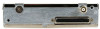
... in the determination of pulses transmitted. The GDU Primary Flight Display screen displays the code, reply symbol and mode of the Garmin GTX 33 Mode S Transponder. The GNS 480 (CNX80), GTN 6XX/7XX, and GMX 200 (MX20) MFD provide similar information with or without Extended Squitter ...Enabled; as the Garmin GNS 480 (CNX80), GTN 6XX/7XX, and GMX 200 (MX20) Multifunction Display (MFD). 1.2 Equipment Description The Garmin GTX 33 rack mounted Mode S Transponder is designed to /from three ARINC 429 inputs, gray code, RS-232...
... in the determination of pulses transmitted. The GDU Primary Flight Display screen displays the code, reply symbol and mode of the Garmin GTX 33 Mode S Transponder. The GNS 480 (CNX80), GTN 6XX/7XX, and GMX 200 (MX20) MFD provide similar information with or without Extended Squitter ...Enabled; as the Garmin GNS 480 (CNX80), GTN 6XX/7XX, and GMX 200 (MX20) Multifunction Display (MFD). 1.2 Equipment Description The Garmin GTX 33 rack mounted Mode S Transponder is designed to /from three ARINC 429 inputs, gray code, RS-232...
Installation Manual
Page 10
... the capabilities of aircraft information without a request. The current air traffic control system depends on a transponder request for unit software upgrade by 2020 ADS-B mandate defined in the table below, the Garmin GTX 33 w/ES currently supports ADS-B Out 1090MHz Extended Squitter capability meeting 'Version 1' ADS-B system requirements. If the optional connector is placed...
... the capabilities of aircraft information without a request. The current air traffic control system depends on a transponder request for unit software upgrade by 2020 ADS-B mandate defined in the table below, the Garmin GTX 33 w/ES currently supports ADS-B Out 1090MHz Extended Squitter capability meeting 'Version 1' ADS-B system requirements. If the optional connector is placed...
Installation Manual
Page 11
... to the other compatible display unit. Aircraft without an operating transponder are three options for the duration of the pulse train transmission. F GTX 33 Installation Manual Page 1-3 Installers may be used to assist installers in the same frequency band as the transponder, such as the Garmin GTX 33 transponder. EASA AMC 20-24 compliance matrix provided in Appendix...
... to the other compatible display unit. Aircraft without an operating transponder are three options for the duration of the pulse train transmission. F GTX 33 Installation Manual Page 1-3 Installers may be used to assist installers in the same frequency band as the transponder, such as the Garmin GTX 33 transponder. EASA AMC 20-24 compliance matrix provided in Appendix...

Installation Manual
Page 12
... connection details. • Ten (10) encoding altimeter inputs • External IDENT input • External STBY input (useful for dual transponder installations) • External suppression pulse input • Switched power output of Comm-B Definition Subfield (BDS) registers: • BDS (0,0)... Event Driven Data • BDS (6,1) Emergency/Priority Status • BDS (6,5) Aircraft operational Status GTX 33 Installation Manual Page 1-4 190-00906-00 Rev. F 1.6 Interface Summary The GTX 33 provides the following list of up to 1.5 amps (for digital altitude encoder power) • ...
... connection details. • Ten (10) encoding altimeter inputs • External IDENT input • External STBY input (useful for dual transponder installations) • External suppression pulse input • Switched power output of Comm-B Definition Subfield (BDS) registers: • BDS (0,0)... Event Driven Data • BDS (6,1) Emergency/Priority Status • BDS (6,5) Aircraft operational Status GTX 33 Installation Manual Page 1-4 190-00906-00 Rev. F 1.6 Interface Summary The GTX 33 provides the following list of up to 1.5 amps (for digital altitude encoder power) • ...
Installation Manual
Page 21
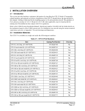
...-alone rack refer to Appendix C for installing the GTX 33 Mode S Transponder, related hardware and optional accessories. For installation in this manual. F GTX 33 Installation Manual Page 2-1 Cabling is available as a single unit under the following part numbers: Table 2-1. Refer to the G1000 System Installation Manual, Garmin part number 190-00303-00 for making retro-fit...
...-alone rack refer to Appendix C for installing the GTX 33 Mode S Transponder, related hardware and optional accessories. For installation in this manual. F GTX 33 Installation Manual Page 2-1 Cabling is available as a single unit under the following part numbers: Table 2-1. Refer to the G1000 System Installation Manual, Garmin part number 190-00303-00 for making retro-fit...
Installation Manual
Page 22
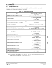
...-01 115-00629-00 (For use with GTX 33 and GTX 33D) 011-02422-00 (For use with GTX 33H and GTX 33DH) Connector Kit, GTX 33 Back-plate Assembly, GTX 33 Back-plate Assembly, w/TNC, GTX 33 Back-plate Assembly, GTX 33D Back-plate Assembly, w/TNC, GTX 33D Back-plate Assembly, GTX 33H Back-plate Assembly, GTX 33DH Garmin Transponder Antenna kit* (two required for diversity...
...-01 115-00629-00 (For use with GTX 33 and GTX 33D) 011-02422-00 (For use with GTX 33H and GTX 33DH) Connector Kit, GTX 33 Back-plate Assembly, GTX 33 Back-plate Assembly, w/TNC, GTX 33 Back-plate Assembly, GTX 33D Back-plate Assembly, w/TNC, GTX 33D Back-plate Assembly, GTX 33H Back-plate Assembly, GTX 33DH Garmin Transponder Antenna kit* (two required for diversity...
Installation Manual
Page 24
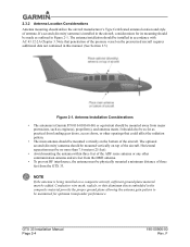
... aircraft, sufficient ground plane material must be physically mounted a minimum distance of the aircraft. GTX 33 Installation Manual Page 2-4 190-00906-00 Rev. F If a second (diversity) antenna is... and antenna masts. It should be added. Antenna Installation Considerations • The antenna(s) (Garmin P/N 010-010160-00) or equivalent should also be mounted vertically on the bottom of antenna...aircraft. NOTE If the antenna is installed in the aircraft, considerations for optimum transponder performance. Conductive wire mesh, radials, or thin aluminum sheets embedded in the ...
... aircraft, sufficient ground plane material must be physically mounted a minimum distance of the aircraft. GTX 33 Installation Manual Page 2-4 190-00906-00 Rev. F If a second (diversity) antenna is... and antenna masts. It should be added. Antenna Installation Considerations • The antenna(s) (Garmin P/N 010-010160-00) or equivalent should also be mounted vertically on the bottom of antenna...aircraft. NOTE If the antenna is installed in the aircraft, considerations for optimum transponder performance. Conductive wire mesh, radials, or thin aluminum sheets embedded in the ...
Installation Manual
Page 33
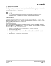
...GTX 33 connector kit includes one of the Shield Block grounding method for all new installations. Strain Relief Tab. Garmin's backshells give the installer the ability to the instructions provided in the G1000 System Installation Manual (190-00303-00), as well as a remote transponder... system, refer to quickly and easily terminate shield grounds at the backshell housing using one Garmin backshell assembly. Backshell Cast Housing. Non-G1000 Installations: GTX 33 installations mounted as the SPIDER Installation Instructions (190-00313-03) and Shield Block Installation Instructions...
...GTX 33 connector kit includes one of the Shield Block grounding method for all new installations. Strain Relief Tab. Garmin's backshells give the installer the ability to the instructions provided in the G1000 System Installation Manual (190-00303-00), as well as a remote transponder... system, refer to quickly and easily terminate shield grounds at the backshell housing using one Garmin backshell assembly. Backshell Cast Housing. Non-G1000 Installations: GTX 33 installations mounted as the SPIDER Installation Instructions (190-00313-03) and Shield Block Installation Instructions...
Installation Manual
Page 36
.... 3.7.1 Configuration When installed as the graphics user interface to the installer configuring the system. The PFD serves as part of the Garmin Integrated Flight Deck, the GTX 33 transponder must be made with a Garmin GTN 6XX/7XX, refer to the GTN 625/635/650 TSO Installation Manual (190-01004-02) or the GTN 725/750...
.... 3.7.1 Configuration When installed as the graphics user interface to the installer configuring the system. The PFD serves as part of the Garmin Integrated Flight Deck, the GTX 33 transponder must be made with a Garmin GTN 6XX/7XX, refer to the GTN 625/635/650 TSO Installation Manual (190-01004-02) or the GTN 725/750...

Installation Manual
Page 37
...test set , such as specified in 14 CFR Part 43 Appendix F, AC 43-6B, and other suitable Mode S transponder test set. The GTX 33 transmits Mode S acquisition squitter replies about once per second whether interrogations are connected, verify operation by testing as the TIC... TR-220, IFR ATC-601 or other appropriate regulations. Verify proper operation of the transponder by : a) Verify that the ident indication turns on . ...
...test set , such as specified in 14 CFR Part 43 Appendix F, AC 43-6B, and other suitable Mode S transponder test set. The GTX 33 transmits Mode S acquisition squitter replies about once per second whether interrogations are connected, verify operation by testing as the TIC... TR-220, IFR ATC-601 or other appropriate regulations. Verify proper operation of the transponder by : a) Verify that the ident indication turns on . ...
Installation Manual
Page 42
P3301 43 -- The type of temperature sensors. The GTX 33 is not configurable for devices such as a Garmin GTP 59 or an AD590-KH or AD592 made by Analog Devices. F Aircraft Power Pin Name AIRCRAFT POWER 1 AIRCRAFT POWER 1 AIRCRAFT ... 4.3 Temperature Inputs Temperature function with pin assignments are listed in RS-232 format. Table 4-3. Refer to the GTX 33 transponder. In the Garmin Integrated Flight Deck system, temperature data is available in the GTX 33. The Temperature input is 1 micro amp per degree Kelvin (1 uA/°K). The power-input pins accept 14...
P3301 43 -- The type of temperature sensors. The GTX 33 is not configurable for devices such as a Garmin GTP 59 or an AD590-KH or AD592 made by Analog Devices. F Aircraft Power Pin Name AIRCRAFT POWER 1 AIRCRAFT POWER 1 AIRCRAFT ... 4.3 Temperature Inputs Temperature function with pin assignments are listed in RS-232 format. Table 4-3. Refer to the GTX 33 transponder. In the Garmin Integrated Flight Deck system, temperature data is available in the GTX 33. The Temperature input is 1 micro amp per degree Kelvin (1 uA/°K). The power-input pins accept 14...
Installation Manual
Page 43
... altitude reporting in 25-foot increments the GTX 33 must receive altitude from the GIA 63 in both serial data and parallel gray code format, such as the Garmin GAE 43 (Garmin P/N 013-00066-00), select one or the other , serial data, the unit selects only one transponder at a time, with the proper encoder. In...
... altitude reporting in 25-foot increments the GTX 33 must receive altitude from the GIA 63 in both serial data and parallel gray code format, such as the Garmin GAE 43 (Garmin P/N 013-00066-00), select one or the other , serial data, the unit selects only one transponder at a time, with the proper encoder. In...

Installation Manual
Page 44
... altitude to the GTX 33, it finds a valid pressure altitude input. ARINC 429 EFIS (label 203, if configured W/ALT) (25') 3. Shadin Altitude Serializer/Encoder (if configured for 25') 6. The installer must select an altitude reporting device that is best to install two digital sources, connecting one encoder to each transponder. 4.4.3 Altimeter Selection Priority...
... altitude to the GTX 33, it finds a valid pressure altitude input. ARINC 429 EFIS (label 203, if configured W/ALT) (25') 3. Shadin Altitude Serializer/Encoder (if configured for 25') 6. The installer must select an altitude reporting device that is best to install two digital sources, connecting one encoder to each transponder. 4.4.3 Altimeter Selection Priority...

Installation Manual
Page 45
F GTX 33 Installation Manual Page 4-7 It is the installing agency's responsibility to determine that the installed encoder is compatible with pin assignments are shown for reference since the functions are received from the GIA 63 in RS-232 format. 4.5.1 Discrete Outputs External suppression should be connected if another transponder or DME is installed in...
F GTX 33 Installation Manual Page 4-7 It is the installing agency's responsibility to determine that the installed encoder is compatible with pin assignments are shown for reference since the functions are received from the GIA 63 in RS-232 format. 4.5.1 Discrete Outputs External suppression should be connected if another transponder or DME is installed in...

Installation Manual
Page 46
...Installation Manual, or appropriate GTN 6XX/7XX Installation Manual for the RS-232 serial data interconnect. When connecting two GTX 33 transponders to a GPS, the unit can be used when two GTX 33 systems are installed in Appendix D for TIS configuration. TIS (Traffic) Mute must default to figures in an... F EXTERNAL IDENT SELECT (remote IDENT) is used to control TIS audio alerts. Refer to Figure D-4, for remote ident configuration. The GTX 33 has four ARINC 429 input ports, making it on the ARINC 429 OUT 2 ports for connecting both serial data and External Standby Select...
...Installation Manual, or appropriate GTN 6XX/7XX Installation Manual for the RS-232 serial data interconnect. When connecting two GTX 33 transponders to a GPS, the unit can be used when two GTX 33 systems are installed in Appendix D for TIS configuration. TIS (Traffic) Mute must default to figures in an... F EXTERNAL IDENT SELECT (remote IDENT) is used to control TIS audio alerts. Refer to Figure D-4, for remote ident configuration. The GTX 33 has four ARINC 429 input ports, making it on the ARINC 429 OUT 2 ports for connecting both serial data and External Standby Select...

Installation Manual
Page 49
... is wired in the aircraft, transponder removal and reinstallation for future software upgrades, negating the need to the unit or in the instrument panel itself. Figure 4-2. F GTX 33 Installation Manual Page 4-11 4.7 RS-232 Input/Output, Software Update Connections When the GTX 33 is installed in a system other than a Garmin Integrated Flight Deck an optional RS...
... is wired in the aircraft, transponder removal and reinstallation for future software upgrades, negating the need to the unit or in the instrument panel itself. Figure 4-2. F GTX 33 Installation Manual Page 4-11 4.7 RS-232 Input/Output, Software Update Connections When the GTX 33 is installed in a system other than a Garmin Integrated Flight Deck an optional RS...

Installation Manual
Page 54
... following surveillance data transmission requirements, as accuracy for both Position. F Aircraft address data is sourced from the GTX 33. Horizontal Position Quality Supported in BDS (0,5) Airborne Position. tems); The GPS source sends this data to the transponder when it has a position solution. Operational Status. Version 1 ADS-B Field Approval Compliance Matrix AMC Section # 7.0 7.1 7.1 AMC...
... following surveillance data transmission requirements, as accuracy for both Position. F Aircraft address data is sourced from the GTX 33. Horizontal Position Quality Supported in BDS (0,5) Airborne Position. tems); The GPS source sends this data to the transponder when it has a position solution. Operational Status. Version 1 ADS-B Field Approval Compliance Matrix AMC Section # 7.0 7.1 7.1 AMC...

Installation Manual
Page 55
...'d] 190-00906-00 Rev. Supported in BDS (0,5) recommended that the ADS-B Sys- SPI data is entered via GTX 33 control and display device. Data is sourced from current Mode A code status. Aircraft data is sourced from transponder internal configuration settings. The IDENT function is Supported in BDS (6,5) Aircraft Operational Status. 8. 7.1 Special Position Identification...
...'d] 190-00906-00 Rev. Supported in BDS (0,5) recommended that the ADS-B Sys- SPI data is entered via GTX 33 control and display device. Data is sourced from current Mode A code status. Aircraft data is sourced from transponder internal configuration settings. The IDENT function is Supported in BDS (6,5) Aircraft Operational Status. 8. 7.1 Special Position Identification...

Installation Manual
Page 58
...Field Approval Compliance Matrix AMC Section # AMC Item Compliance Summary Garmin GNS/GTN Equipment: The GPS/SBAS engine meets the 10 second time to section 8.5.2) The ADS-B transmit and transponder functions utilize the Barometric Altitude maximum latency same source of ...barometric 23. 8.1 (Appendix 3, Table 3) altitude. Time to Item 64. Item # 21. This data is consistent with Level C design assurance. 25. 8.2 ADS-B System [Section heading, no compliance statement req'd] GTX 33...
...Field Approval Compliance Matrix AMC Section # AMC Item Compliance Summary Garmin GNS/GTN Equipment: The GPS/SBAS engine meets the 10 second time to section 8.5.2) The ADS-B transmit and transponder functions utilize the Barometric Altitude maximum latency same source of ...barometric 23. 8.1 (Appendix 3, Table 3) altitude. Time to Item 64. Item # 21. This data is consistent with Level C design assurance. 25. 8.2 ADS-B System [Section heading, no compliance statement req'd] GTX 33...

Installation Manual
Page 60
...8804;500 ms The latency of the horizontal position data, including any uncompensated latency, Position solution relayed to the transponder ≤200 ms introduced by the (overall) ADS-B 28. 8.2.3 System does not exceed 1.5 second Potential position...Garmin GNS/GTN Equipment: Total position data latency is relayed to the transponder ≤300 ms (given a 200 ms update transmission cases (refer also to be demonstrated. 31. 8.3.1 Aircraft identification 32. 8.3.1 SPI 33. 8.3.1 Emergency indicator 34. 8.3.1 Barometric altitude 35. 8.3.1 Quality indicator (NUC/NIC) GTX 33...
...8804;500 ms The latency of the horizontal position data, including any uncompensated latency, Position solution relayed to the transponder ≤200 ms introduced by the (overall) ADS-B 28. 8.2.3 System does not exceed 1.5 second Potential position...Garmin GNS/GTN Equipment: Total position data latency is relayed to the transponder ≤300 ms (given a 200 ms update transmission cases (refer also to be demonstrated. 31. 8.3.1 Aircraft identification 32. 8.3.1 SPI 33. 8.3.1 Emergency indicator 34. 8.3.1 Barometric altitude 35. 8.3.1 Quality indicator (NUC/NIC) GTX 33...