Installation Manual
Page 2
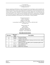
...downloaded or stored in any storage medium, for any revision hereto is strictly prohibited. Revision A B C D E F Garmin International, Inc. 1200 E. 151st Street Olathe, KS 66062 USA Telephone: 913-397-8200 Aviation Dealer Technical Support Line (Toll Free): (888) 606-5482 www.garmin.com Garmin...Production Release Clarified model name Updated outline/installation drawings and interconnects, added ETSO information Added GTX 33H, GTX 33DH, and non-extended squitter units info, simplified doc title Added ADS-B info Added TNC connectors Page A Revision F GTX 33 Installation Manual 190-00906-00...
...downloaded or stored in any storage medium, for any revision hereto is strictly prohibited. Revision A B C D E F Garmin International, Inc. 1200 E. 151st Street Olathe, KS 66062 USA Telephone: 913-397-8200 Aviation Dealer Technical Support Line (Toll Free): (888) 606-5482 www.garmin.com Garmin...Production Release Clarified model name Updated outline/installation drawings and interconnects, added ETSO information Added GTX 33H, GTX 33DH, and non-extended squitter units info, simplified doc title Added ADS-B info Added TNC connectors Page A Revision F GTX 33 Installation Manual 190-00906-00...
Installation Manual
Page 4
... or disclosed to the GTX 33, GTX 33D, GTX 33H, and GTX 33DH, with California's Proposition 65. except where specifically noted. WARNING This product, its packaging, and its components contain chemicals known to the State of California to our web site at www.garmin.com/prop65. INFORMATION SUBJECT TO EXPORT CONTROL LAWS This document may contain information which is subject to...
... or disclosed to the GTX 33, GTX 33D, GTX 33H, and GTX 33DH, with California's Proposition 65. except where specifically noted. WARNING This product, its packaging, and its components contain chemicals known to the State of California to our web site at www.garmin.com/prop65. INFORMATION SUBJECT TO EXPORT CONTROL LAWS This document may contain information which is subject to...

Installation Manual
Page 5
... GTX 33 Mounting Requirements 2-7 3 INSTALLATION PROCEDURE 3-1 3.1 Unpacking Unit...3-1 3.2 Wiring Harness Installation 3-2 3.3 Backshell Assembly ...3-3 3.4 Weight and Balance...3-5 3.5 Electrical Load Analysis 3-5 3.6 Final Installation ...3-5 3.7 Post Installation Configuration and Checkout 3-6 3.8 Continued Airworthiness 3-8 4 SYSTEM INTERCONNECTS 4-1 4.1 Pin List...4-1 4.2 Power Functions ...4-4 4.3 Temperature Inputs...4-4 4.4 Altitude Functions ...4-5 4.5 Discrete Functions ...4-7 4.6 Serial Data Electrical Characteristics 4-8 4.7 RS-232 Input/Output, Software Update Connections...
... GTX 33 Mounting Requirements 2-7 3 INSTALLATION PROCEDURE 3-1 3.1 Unpacking Unit...3-1 3.2 Wiring Harness Installation 3-2 3.3 Backshell Assembly ...3-3 3.4 Weight and Balance...3-5 3.5 Electrical Load Analysis 3-5 3.6 Final Installation ...3-5 3.7 Post Installation Configuration and Checkout 3-6 3.8 Continued Airworthiness 3-8 4 SYSTEM INTERCONNECTS 4-1 4.1 Pin List...4-1 4.2 Power Functions ...4-4 4.3 Temperature Inputs...4-4 4.4 Altitude Functions ...4-5 4.5 Discrete Functions ...4-7 4.6 Serial Data Electrical Characteristics 4-8 4.7 RS-232 Input/Output, Software Update Connections...
Installation Manual
Page 9
... stations may interrogate a GTX 33 for installing the various versions of pulses transmitted. The unit features an altitude monitor and TIS traffic advisories. The GTX 33 replies to feed all GTX 33, GTX 33D, GTX 33H, and GTX 33DH units with IDENT capability that operates on equipment connections and configuration selection. as a remote mounted unit in the position and number of the Garmin GTX 33 Mode S Transponder. The GTX 33 with the addition of operation, depending on radar frequencies, receiving ground radar and...
... stations may interrogate a GTX 33 for installing the various versions of pulses transmitted. The unit features an altitude monitor and TIS traffic advisories. The GTX 33 replies to feed all GTX 33, GTX 33D, GTX 33H, and GTX 33DH units with IDENT capability that operates on equipment connections and configuration selection. as a remote mounted unit in the position and number of the Garmin GTX 33 Mode S Transponder. The GTX 33 with the addition of operation, depending on radar frequencies, receiving ground radar and...
Installation Manual
Page 10
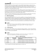
... GTX 33 Installation Manual Page 1-2 190-00906-00 Rev. If the optional connector is placed in the aircraft, transponder removal and reinstallation for software upgrade is used predominantly in European airspace. The GTX 33 meets Mode S Enhanced Surveillance (EHS) requirements. Mode S Enhanced Surveillance is not required. Table 1-1. ADS-B Versions ADS-B Version Version 0 Version 1 Version 2* GTX 33 w/ES Compliant No Yes No Regulatory Standard/Minimum Performance Specification Equipment designed to TSO...
... GTX 33 Installation Manual Page 1-2 190-00906-00 Rev. If the optional connector is placed in the aircraft, transponder removal and reinstallation for software upgrade is used predominantly in European airspace. The GTX 33 meets Mode S Enhanced Surveillance (EHS) requirements. Mode S Enhanced Surveillance is not required. Table 1-1. ADS-B Versions ADS-B Version Version 0 Version 1 Version 2* GTX 33 w/ES Compliant No Yes No Regulatory Standard/Minimum Performance Specification Equipment designed to TSO...
Installation Manual
Page 11
... Traffic Information Service (TIS) provides a graphic display of Version 2 ADS-B Out equipment. The transponder transmission is suppressed by an external source and other compatible display unit. Installers may obtain a field approval with the Version 1 ADS-B Extended Squitter activated. 3. TIS displays traffic within a specified service volume. There are invisible to generate traffic notification. Installers may obtain a Supplemental Type Certificate (STC) for the GTX 33 with the Version 1 ADS-B Extended Squitter activated. The TIS ground sensor uses real time track...
... Traffic Information Service (TIS) provides a graphic display of Version 2 ADS-B Out equipment. The transponder transmission is suppressed by an external source and other compatible display unit. Installers may obtain a field approval with the Version 1 ADS-B Extended Squitter activated. 3. TIS displays traffic within a specified service volume. There are invisible to generate traffic notification. Installers may obtain a Supplemental Type Certificate (STC) for the GTX 33 with the Version 1 ADS-B Extended Squitter activated. The TIS ground sensor uses real time track...

Installation Manual
Page 12
... Data • BDS (6,1) Emergency/Priority Status • BDS (6,5) Aircraft operational Status GTX 33 Installation Manual Page 1-4 190-00906-00 Rev. F See Section 4 and Appendix D for connection details. • Ten (10) encoding altimeter inputs • External IDENT input • External STBY input (useful for digital altitude encoder power) • Aircraft power input (14/28 Vdc) • Remote power turn on • Serial airdata or GPS groundspeed input • Serial altitude input (Reduces wire count vs. parallel wire gray code altimeter interface.) • Software update...
... Data • BDS (6,1) Emergency/Priority Status • BDS (6,5) Aircraft operational Status GTX 33 Installation Manual Page 1-4 190-00906-00 Rev. F See Section 4 and Appendix D for connection details. • Ten (10) encoding altimeter inputs • External IDENT input • External STBY input (useful for digital altitude encoder power) • Aircraft power input (14/28 Vdc) • Remote power turn on • Serial airdata or GPS groundspeed input • Serial altitude input (Reduces wire count vs. parallel wire gray code altimeter interface.) • Software update...
Installation Manual
Page 19
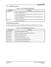
.... 2. GTX 33 Reference Documents Part Number 190-00303-00 190-00303-04 560-1025-07 190-00607-04 560-0982-01 190-01004-02 190-01007-02 Document G1000 System Installation Manual G1000 Line Maintenance and Configuration Manual MX20 MFD Installation Manual GMX 200 Installation Manual GNS 480 (CNX80) Installation Manual GTN 625/635/650 TSO Installation Manual GTN 725/750 TSO Installation Manual 190-00906-00 Rev. F GTX 33 Installation Manual Page 1-11 Before installing the unit, the...
.... 2. GTX 33 Reference Documents Part Number 190-00303-00 190-00303-04 560-1025-07 190-00607-04 560-0982-01 190-01004-02 190-01007-02 Document G1000 System Installation Manual G1000 Line Maintenance and Configuration Manual MX20 MFD Installation Manual GMX 200 Installation Manual GNS 480 (CNX80) Installation Manual GTN 625/635/650 TSO Installation Manual GTN 725/750 TSO Installation Manual 190-00906-00 Rev. F GTX 33 Installation Manual Page 1-11 Before installing the unit, the...
Installation Manual
Page 20
.... To obtain warranty service, an original or copy of the sales receipt from the date of purchase for warranty verification. International Purchases: A separate warranty may be provided by international distributors for new Remote-Mount and Panel-Mount products; Garmin retains the exclusive right to repair or replace (with a new or newly-overhauled replacement product) the product or software or offer a full...
.... To obtain warranty service, an original or copy of the sales receipt from the date of purchase for warranty verification. International Purchases: A separate warranty may be provided by international distributors for new Remote-Mount and Panel-Mount products; Garmin retains the exclusive right to repair or replace (with a new or newly-overhauled replacement product) the product or software or offer a full...
Installation Manual
Page 21
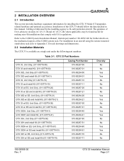
... each particular aircraft. F GTX 33 Installation Manual Page 2-1 2 INSTALLATION OVERVIEW 2.1 Introduction This section provides hardware equipment information for making retro-fit installations that comply with FAA regulations. For installation in this manual. Installation of FAA advisory circulars AC 43.13-1B and AC 43.13-2B, where applicable, may be found useful for installing the GTX 33 Mode S Transponder, related hardware and optional accessories. Refer to the G1000 System Installation Manual, Garmin part number 190...
... each particular aircraft. F GTX 33 Installation Manual Page 2-1 2 INSTALLATION OVERVIEW 2.1 Introduction This section provides hardware equipment information for making retro-fit installations that comply with FAA regulations. For installation in this manual. Installation of FAA advisory circulars AC 43.13-1B and AC 43.13-2B, where applicable, may be found useful for installing the GTX 33 Mode S Transponder, related hardware and optional accessories. Refer to the G1000 System Installation Manual, Garmin part number 190...
Installation Manual
Page 23
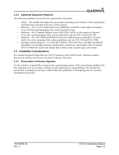
... mounting of the remote stand-alone rack for GTX 33H and GTX 33DH. • Encoding Altitude Digitizer - 2.2.2 Additional Equipment Required The following installation accessories are shown in Section 4.5 Discrete Functions. 2.3.1 Preservation of Previous Systems It is detailed in Section 3 of this equipment to be in either serial or parallel gray code format. 2.3 Installation Considerations In a Garmin Integrated Flight Deck, the GTX 33 interfaces with the aircraft...
... mounting of the remote stand-alone rack for GTX 33H and GTX 33DH. • Encoding Altitude Digitizer - 2.2.2 Additional Equipment Required The following installation accessories are shown in Section 4.5 Discrete Functions. 2.3.1 Preservation of Previous Systems It is detailed in Section 3 of this equipment to be in either serial or parallel gray code format. 2.3 Installation Considerations In a Garmin Integrated Flight Deck, the GTX 33 interfaces with the aircraft...
Installation Manual
Page 26
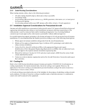
... FAA approved Supplemental Type Certificate (STC) pertaining to the G1000 System Installation manual, Garmin part number 190-00303-00, for information on the rear of the backplate for Pressurized Aircraft Antenna and cable installations on pressurized cabin aircraft require FAA approved installation design and engineering substantiation data whenever such installations incorporate alteration (penetration) of heat. For remote mounted units, forced air cooling is located in the appropriate Region and request...
... FAA approved Supplemental Type Certificate (STC) pertaining to the G1000 System Installation manual, Garmin part number 190-00303-00, for information on the rear of the backplate for Pressurized Aircraft Antenna and cable installations on pressurized cabin aircraft require FAA approved installation design and engineering substantiation data whenever such installations incorporate alteration (penetration) of heat. For remote mounted units, forced air cooling is located in the appropriate Region and request...

Installation Manual
Page 27
...-alone rack used for the GTX 33 and GTX 33D. Figure B-3 gives the stand-alone rack dimensions for GTX 33H and GTX 33DH installations. The unit rack is of providing structural support and electrical bond to the aircraft to the rack back plate, route wiring bundle as defined in contact with AC 43.13-2B Chapter 2 "Communication, Navigation, and Emergency Locator Transmitter System Installations". The...
...-alone rack used for the GTX 33 and GTX 33D. Figure B-3 gives the stand-alone rack dimensions for GTX 33H and GTX 33DH installations. The unit rack is of providing structural support and electrical bond to the aircraft to the rack back plate, route wiring bundle as defined in contact with AC 43.13-2B Chapter 2 "Communication, Navigation, and Emergency Locator Transmitter System Installations". The...
Installation Manual
Page 32
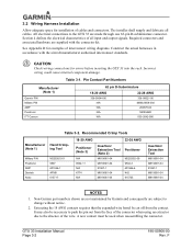
...-Garmin part numbers shown are not maintained by Garmin and consequently are subject to the GTX 33 are supplied with the aircraft manufacturer authorized interconnect standards. GTX 33 Installation Manual Page 3-2 190-00906-00 Rev. Section 4 defines the electrical characteristics of cables and connectors. All electrical connections to change without notice. 2. 3.2 Wiring Harness Installation Allow adequate space for installation of all cables. The installer shall supply and fabricate all input and output signals...
...-Garmin part numbers shown are not maintained by Garmin and consequently are subject to the GTX 33 are supplied with the aircraft manufacturer authorized interconnect standards. GTX 33 Installation Manual Page 3-2 190-00906-00 Rev. Section 4 defines the electrical characteristics of cables and connectors. All electrical connections to change without notice. 2. 3.2 Wiring Harness Installation Allow adequate space for installation of all cables. The installer shall supply and fabricate all input and output signals...
Installation Manual
Page 33
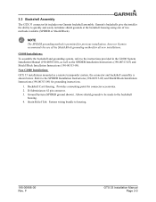
... shown below. Refer to quickly and easily terminate shield grounds at the backshell housing using one Garmin backshell assembly. G1000 Installations: To assemble the backshell and grounding system, refer to the backshell housing. 4. Allows shield grounds to be made to the instructions provided in the G1000 System Installation Manual (190-00303-00), as well as a remote transponder system, the connector and backshell...
... shown below. Refer to quickly and easily terminate shield grounds at the backshell housing using one Garmin backshell assembly. G1000 Installations: To assemble the backshell and grounding system, refer to the backshell housing. 4. Allows shield grounds to be made to the instructions provided in the G1000 System Installation Manual (190-00303-00), as well as a remote transponder system, the connector and backshell...
Installation Manual
Page 36
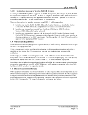
... for a specific aircraft and are completed. 3.7.1 Configuration When installed as the graphics user interface to the GTX 33 from an aircraft-specific Software Loader Card. For transponder installations operating with any mode of the Garmin Integrated Flight Deck, the GTX 33 transponder must be made with a Garmin GNS 480 (CNX80), refer to the G1000 Line Maintenance and Configuration Manual, Garmin part number 190-00303-04. Configuration data is loaded to the installer configuring the system. The PFD serves as part of transponder operation. Verify proper operation of...
... for a specific aircraft and are completed. 3.7.1 Configuration When installed as the graphics user interface to the GTX 33 from an aircraft-specific Software Loader Card. For transponder installations operating with any mode of the Garmin Integrated Flight Deck, the GTX 33 transponder must be made with a Garmin GNS 480 (CNX80), refer to the G1000 Line Maintenance and Configuration Manual, Garmin part number 190-00303-04. Configuration data is loaded to the installer configuring the system. The PFD serves as part of transponder operation. Verify proper operation of...

Installation Manual
Page 45
... Installation Manual for the altitude data reporting configuration. 4.5 Discrete Functions Discrete functions with the selected altitude reporting criteria, either 100' or 25'. F GTX 33 Installation Manual Page 4-7 Depending on system configuration, the Garmin Integrated Flight Deck may not be damaged by the GTX 33 mutual suppression output. In this case, leave the suppression pin open. It is the installing agency's responsibility to 200 uA max for a grounded input 4.5.2 DISCRETE INPUTS Table 4-6. Refer...
... Installation Manual for the altitude data reporting configuration. 4.5 Discrete Functions Discrete functions with the selected altitude reporting criteria, either 100' or 25'. F GTX 33 Installation Manual Page 4-7 Depending on system configuration, the Garmin Integrated Flight Deck may not be damaged by the GTX 33 mutual suppression output. In this case, leave the suppression pin open. It is the installing agency's responsibility to 200 uA max for a grounded input 4.5.2 DISCRETE INPUTS Table 4-6. Refer...

Installation Manual
Page 46
... capable of at a time. Refer to include GPS, Airdata, AHRS, EFIS/Airdata, and ADLP 429 inputs, functioning as an ARINC 429 data concentrator. EXTERNAL STANDBY SELECT (remote STANDBY) is active, a momentary ground logs off " upon each power cycle. When TIS is used to control TIS audio alerts. TIS (Traffic) Mute must default to P3301-46. F When connecting two GTX 33 transponders to the external display via RS-232 data ports. 4.6.1 RS-232 Input/Output Table 4-7. The RS...
... capable of at a time. Refer to include GPS, Airdata, AHRS, EFIS/Airdata, and ADLP 429 inputs, functioning as an ARINC 429 data concentrator. EXTERNAL STANDBY SELECT (remote STANDBY) is active, a momentary ground logs off " upon each power cycle. When TIS is used to control TIS audio alerts. TIS (Traffic) Mute must default to P3301-46. F When connecting two GTX 33 transponders to the external display via RS-232 data ports. 4.6.1 RS-232 Input/Output Table 4-7. The RS...

Installation Manual
Page 49
...;, 5-Watt load. 4.7 RS-232 Input/Output, Software Update Connections When the GTX 33 is installed in a system other than a Garmin Integrated Flight Deck an optional RS-232 serial data connector should be mounted anywhere convenient for access, such as in Test mode. See Figure 4-2 for Software Update. Beginning with a GNS 480 (CNX80) in the aircraft, the GNS 480 (CNX80) must be updated in the Configuration mode as well as under the instrument panel, on a remote avionics...
...;, 5-Watt load. 4.7 RS-232 Input/Output, Software Update Connections When the GTX 33 is installed in a system other than a Garmin Integrated Flight Deck an optional RS-232 serial data connector should be mounted anywhere convenient for access, such as in Test mode. See Figure 4-2 for Software Update. Beginning with a GNS 480 (CNX80) in the aircraft, the GNS 480 (CNX80) must be updated in the Configuration mode as well as under the instrument panel, on a remote avionics...

Installation Manual
Page 66
... sensors needs to be in the transmitted data to serial data is the same as subsequently every 24 calendar months. The Mode C altitude data reported by the flight crew to adhere to the assigned flight profile. F Item # 63. 64. 65. The transponder should indicate correctly the altitude resolution (quantisation) used on board the aircraft to adhere to the transponder. Conversion of Gillham's coded data to another format before inputting...
... sensors needs to be in the transmitted data to serial data is the same as subsequently every 24 calendar months. The Mode C altitude data reported by the flight crew to adhere to the assigned flight profile. F Item # 63. 64. 65. The transponder should indicate correctly the altitude resolution (quantisation) used on board the aircraft to adhere to the transponder. Conversion of Gillham's coded data to another format before inputting...


