
Maintenance Manual
Page 2
No. Number: 190-01277-A3 Rev. 1 Garmin International, Inc. 1200 E. 151st Street Olathe, Kansas 66062 USA 190-01277-A3 Rev. 1 System Maintenance Manual GRA 55/5500 Bell 206 STC Page A System Maintenance Manual GRA 55/5500 Bell 206 STC as installed in Bell 206B, 206L Series Reg. S/N Contains Instructions for Continued Airworthiness for Bell 206 STC Dwg.
No. Number: 190-01277-A3 Rev. 1 Garmin International, Inc. 1200 E. 151st Street Olathe, Kansas 66062 USA 190-01277-A3 Rev. 1 System Maintenance Manual GRA 55/5500 Bell 206 STC Page A System Maintenance Manual GRA 55/5500 Bell 206 STC as installed in Bell 206B, 206L Series Reg. S/N Contains Instructions for Continued Airworthiness for Bell 206 STC Dwg.
Maintenance Manual
Page 5
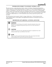
...exported, released, or disclosed to foreign nationals inside or outside of 1979. Visit the Garmin web site (www.garmin.com) for the particular operation. 190-01277-A3 Rev. 1 System Maintenance Manual GRA 55/5500 Bell 206 STC Page i NOTE Notes are used to $1,000,000 under Section 2410...obtaining an export license. This information in this notice with any reproduced portion of Garmin products. DEFINITIONS OF WARNINGS, CAUTIONS, AND NOTES WARNING Warnings are used to bring to the installer's immediate attention that damage to equipment may result if the procedural step is ...
...exported, released, or disclosed to foreign nationals inside or outside of 1979. Visit the Garmin web site (www.garmin.com) for the particular operation. 190-01277-A3 Rev. 1 System Maintenance Manual GRA 55/5500 Bell 206 STC Page i NOTE Notes are used to $1,000,000 under Section 2410...obtaining an export license. This information in this notice with any reproduced portion of Garmin products. DEFINITIONS OF WARNINGS, CAUTIONS, AND NOTES WARNING Warnings are used to bring to the installer's immediate attention that damage to equipment may result if the procedural step is ...

Maintenance Manual
Page 6
... 3-8 4 INSTRUCTIONS FOR CONTINUED AIRWORTHINESS 4-1 4.1 Servicing Information ...4-1 4.2 Periodic Maintenance ...4-1 4.3 Special Tools ...4-1 4.4 Maintenance Intervals ...4-2 5 TROUBLESHOOTING INFORMATION 5-1 5.1 GRA 55/5500 General Troubleshooting 5-1 6 REMOVAL AND REPLACEMENT INFORMATION 6-1 6.1 Unit Installation ...6-1 6.1.1 Installation Procedure 6-1 6.1.2 Removal Procedure 6-1 6.2 Rack Installation ...6-1 6.2.1 Installation Procedure 6-1 6.2.2 Removal Procedure 6-1 6.3 Antenna Installation ...6-1 190-01277-A3 Rev. 1 System Maintenance Manual GRA 55/5500 Bell 206 STC Page ii
... 3-8 4 INSTRUCTIONS FOR CONTINUED AIRWORTHINESS 4-1 4.1 Servicing Information ...4-1 4.2 Periodic Maintenance ...4-1 4.3 Special Tools ...4-1 4.4 Maintenance Intervals ...4-2 5 TROUBLESHOOTING INFORMATION 5-1 5.1 GRA 55/5500 General Troubleshooting 5-1 6 REMOVAL AND REPLACEMENT INFORMATION 6-1 6.1 Unit Installation ...6-1 6.1.1 Installation Procedure 6-1 6.1.2 Removal Procedure 6-1 6.2 Rack Installation ...6-1 6.2.1 Installation Procedure 6-1 6.2.2 Removal Procedure 6-1 6.3 Antenna Installation ...6-1 190-01277-A3 Rev. 1 System Maintenance Manual GRA 55/5500 Bell 206 STC Page ii
Maintenance Manual
Page 7
TABLE OF CONTENT CONTINUED 6.3.1 Installation Procedure 6-1 6.3.2 Removal Procedure 6-2 7 RETURN TO SERVICE PROCEDURE 7-1 7.1 Return to Service ...7-1 7.2 Maintenance Records ...7-1 8 LIMITATIONS AND ADDITIONAL REQUIREMENTS 8-1 8.1 Diagrams ...8-1 8.2 Special Inspection Requirements 8-1 8.3 Application of ...and Distribution 8-1 8.8 Assistance ...8-1 8.9 Implementation and Record Keeping 8-2 9 AIRWORTHINESS LIMITATIONS SECTION 9-1 APPENDIX A AIRCRAFT SPECIFIC INFORMATION A-1 A.1 Weight and Balance ...A-5 190-01277-A3 Rev. 1 System Maintenance Manual GRA 55/5500 Bell 206 STC Page iii
TABLE OF CONTENT CONTINUED 6.3.1 Installation Procedure 6-1 6.3.2 Removal Procedure 6-2 7 RETURN TO SERVICE PROCEDURE 7-1 7.1 Return to Service ...7-1 7.2 Maintenance Records ...7-1 8 LIMITATIONS AND ADDITIONAL REQUIREMENTS 8-1 8.1 Diagrams ...8-1 8.2 Special Inspection Requirements 8-1 8.3 Application of ...and Distribution 8-1 8.8 Assistance ...8-1 8.9 Implementation and Record Keeping 8-2 9 AIRWORTHINESS LIMITATIONS SECTION 9-1 APPENDIX A AIRCRAFT SPECIFIC INFORMATION A-1 A.1 Weight and Balance ...A-5 190-01277-A3 Rev. 1 System Maintenance Manual GRA 55/5500 Bell 206 STC Page iii

Maintenance Manual
Page 8
...-A3 Rev. 1 System Maintenance Manual GRA 55/5500 Bell 206 STC Page iv Figure 3-5. Figure A-2. Figure A-5. Figure A-6. Figure 2-1. Figure 3-1. Figure 3-3. Figure 6-1. Figure 6-2. Figure A-3. Figure A-7. Figure A-8. LIST OF FIGURES GRA 55/5500 Block Diagram 2-1 Installation Tool Page Tabs 3-2 Status Page ...3-3 Configuration Page 3-4 Software Page ...3-5 Diagnostics Page 3-6 Utilities Page ...3-7 GRA 55/5500 Installation 6-2 Rack Installation 6-3 GRA 55/5500 Antenna Installation 6-3 GRA STC Equipment Fuselage Station Location...
...-A3 Rev. 1 System Maintenance Manual GRA 55/5500 Bell 206 STC Page iv Figure 3-5. Figure A-2. Figure A-5. Figure A-6. Figure 2-1. Figure 3-1. Figure 3-3. Figure 6-1. Figure 6-2. Figure A-3. Figure A-7. Figure A-8. LIST OF FIGURES GRA 55/5500 Block Diagram 2-1 Installation Tool Page Tabs 3-2 Status Page ...3-3 Configuration Page 3-4 Software Page ...3-5 Diagnostics Page 3-6 Utilities Page ...3-7 GRA 55/5500 Installation 6-2 Rack Installation 6-3 GRA 55/5500 Antenna Installation 6-3 GRA STC Equipment Fuselage Station Location...

Maintenance Manual
Page 10
...to determine the suitability of the documents for the ICA. 1.5 Definitions The following terminology is used by the installation of the Garmin GRA 55/5500 STC. 1.3 Document Control This document is released, archived, and controlled in compliance with STC engineering data when... 206B, 206L, L-1, L-3, and L-4 rotorcraft, modified by the agency installing the Garmin GRA 55/5500 radar altimeter system under the GRA 55/5500 STC. TX:Transmit 190-01277-A3 Rev. 1 System Maintenance Manual GRA 55/5500 Bell 206 STC Page 1-1 1 INTRODUCTION 1.1 Purpose This document provides Instructions...
...to determine the suitability of the documents for the ICA. 1.5 Definitions The following terminology is used by the installation of the Garmin GRA 55/5500 STC. 1.3 Document Control This document is released, archived, and controlled in compliance with STC engineering data when... 206B, 206L, L-1, L-3, and L-4 rotorcraft, modified by the agency installing the Garmin GRA 55/5500 radar altimeter system under the GRA 55/5500 STC. TX:Transmit 190-01277-A3 Rev. 1 System Maintenance Manual GRA 55/5500 Bell 206 STC Page 1-1 1 INTRODUCTION 1.1 Purpose This document provides Instructions...

Maintenance Manual
Page 11
... Rev. 1 System Maintenance Manual GRA 55/5500 Bell 206 STC Page 1-2 Bell Model 206L1 Maintenance Manual, Bell Document BHT-206L1-MM, Revision 33, 1 June 2012 4. Structural Repair Manual for the modification of the aircraft by the installation of the Garmin GRA 55/5500 Part 27 STC. 1.7.1 Applicability Applies to aircraft altered by the installation of the Garmin GRA 55/5500 Part 27 STC...
... Rev. 1 System Maintenance Manual GRA 55/5500 Bell 206 STC Page 1-2 Bell Model 206L1 Maintenance Manual, Bell Document BHT-206L1-MM, Revision 33, 1 June 2012 4. Structural Repair Manual for the modification of the aircraft by the installation of the Garmin GRA 55/5500 Part 27 STC. 1.7.1 Applicability Applies to aircraft altered by the installation of the Garmin GRA 55/5500 Part 27 STC...

Maintenance Manual
Page 12
GRA 55/5500 Block Diagram System Maintenance Manual GRA 55/5500 Bell 206 STC Page 2-1 The two approved radar altimeter antennas are compatible with an installed Garmin GTN 6XX/7XX for the purpose of providing the optional 50 ft callout as summarized below. The GRA 55/5500 radar altimeter system features: two antenna architecture for transmitting and receiving radio waves...
GRA 55/5500 Block Diagram System Maintenance Manual GRA 55/5500 Bell 206 STC Page 2-1 The two approved radar altimeter antennas are compatible with an installed Garmin GTN 6XX/7XX for the purpose of providing the optional 50 ft callout as summarized below. The GRA 55/5500 radar altimeter system features: two antenna architecture for transmitting and receiving radio waves...

Maintenance Manual
Page 13
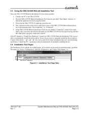
...GRA 55/5500 Retrofit Installation Tool. NOTE A standard USB-A plug to USB-B plug commercial cable (not provided) is required to close the setup wizard. 190-01277-A3 Rev. 1 System Maintenance Manual GRA 55/5500 Bell 206 STC Page 3-1 The last screen of the setup wizard will begin. 3. 3 GRA 55/5500...Installing the GRA 55/5500 Retrofit Installation Tool GRA 55/5500 configuration, calibration, diagnostics, and software upgrades are performed using a personal computer (installed with Microsoft Windows XP Service Pack 3 or later) and the GRA 55/5500 Retrofit Installation Tool, Garmin ...
...GRA 55/5500 Retrofit Installation Tool. NOTE A standard USB-A plug to USB-B plug commercial cable (not provided) is required to close the setup wizard. 190-01277-A3 Rev. 1 System Maintenance Manual GRA 55/5500 Bell 206 STC Page 3-1 The last screen of the setup wizard will begin. 3. 3 GRA 55/5500...Installing the GRA 55/5500 Retrofit Installation Tool GRA 55/5500 configuration, calibration, diagnostics, and software upgrades are performed using a personal computer (installed with Microsoft Windows XP Service Pack 3 or later) and the GRA 55/5500 Retrofit Installation Tool, Garmin ...
Maintenance Manual
Page 14
.... 1 System Maintenance Manual GRA 55/5500 Bell 206 STC Page 3-2 3.3 Using the GRA 55/5500 Retrofit Installation Tool Once the GRA 55/5500 Retrofit Installation Tool has been installed: 1. Power-up and that the USB cable is properly connected to the GRA 55/5500 2. If the PC displays a "Found New Hardware" wizard, the GRA 55/5500 Retrofit Installation Tool was not able to manually install the device...
.... 1 System Maintenance Manual GRA 55/5500 Bell 206 STC Page 3-2 3.3 Using the GRA 55/5500 Retrofit Installation Tool Once the GRA 55/5500 Retrofit Installation Tool has been installed: 1. Power-up and that the USB cable is properly connected to the GRA 55/5500 2. If the PC displays a "Found New Hardware" wizard, the GRA 55/5500 Retrofit Installation Tool was not able to manually install the device...
Maintenance Manual
Page 17
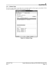
Software Page 190-01277-A3 Rev. 1 System Maintenance Manual GRA 55/5500 Bell 206 STC Page 3-5 Figure 3-4. 3.4.3 Software Page The software page (Figure 3-4) provides a list of currently installed software regions on the GRA 55/5500 as well as an interface to load new software regions to the unit.
Software Page 190-01277-A3 Rev. 1 System Maintenance Manual GRA 55/5500 Bell 206 STC Page 3-5 Figure 3-4. 3.4.3 Software Page The software page (Figure 3-4) provides a list of currently installed software regions on the GRA 55/5500 as well as an interface to load new software regions to the unit.
Maintenance Manual
Page 20
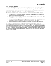
..., antenna height above ground, etc. During the calibration procedure, the GRA 55/5500 Retrofit Installation Tool will report progress updates next to verify antenna installation and the antenna coaxial cables are installed and connected properly. 3. A visual inspection must be performed on a...ft" and "Normal," the unit has been successfully calibrated. 190-01277-A3 Rev. 1 System Maintenance Manual GRA 55/5500 Bell 206 STC Page 3-8 GRA 55/5500 Retrofit Installation Tool must be performed to the "Initiate Calibration Procedure" button. Clicking this button will be attempted: ...
..., antenna height above ground, etc. During the calibration procedure, the GRA 55/5500 Retrofit Installation Tool will report progress updates next to verify antenna installation and the antenna coaxial cables are installed and connected properly. 3. A visual inspection must be performed on a...ft" and "Normal," the unit has been successfully calibrated. 190-01277-A3 Rev. 1 System Maintenance Manual GRA 55/5500 Bell 206 STC Page 3-8 GRA 55/5500 Retrofit Installation Tool must be performed to the "Initiate Calibration Procedure" button. Clicking this button will be attempted: ...
Maintenance Manual
Page 24
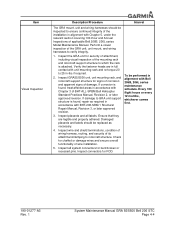
... 12 months, whichever comes first. 190-01277-A3 Rev. 1 System Maintenance Manual GRA 55/5500 Bell 206 STC Page 4-4 Perform a visual inspection of its attachment/clamping to which the rack is found , treat affected areas in accordance with Chapter 3 of wire installation. 5. Inspect connectors for chaffed or damage wires and ensure overall functionality of...
... 12 months, whichever comes first. 190-01277-A3 Rev. 1 System Maintenance Manual GRA 55/5500 Bell 206 STC Page 4-4 Perform a visual inspection of its attachment/clamping to which the rack is found , treat affected areas in accordance with Chapter 3 of wire installation. 5. Inspect connectors for chaffed or damage wires and ensure overall functionality of...

Maintenance Manual
Page 25
...hardware is only required to clean the underneath of less than or equal to the antenna installation. 2. Reinstall the antenna mounting screw, torque as required. Any reworked antenna installation shall have a resistance of the fastener head and the fastener hole. To be performed ... the washer on antennas installed by this STC Item Description/Procedure Interval An electrical bonding test must be performed in BHT-ELEC-SPM CHP 8. 190-01277-A3 Rev. 1 System Maintenance Manual GRA 55/5500 Bell 206 STC Page 4-5 a nut, the technician is installed and properly torqued. 3....
...hardware is only required to clean the underneath of less than or equal to the antenna installation. 2. Reinstall the antenna mounting screw, torque as required. Any reworked antenna installation shall have a resistance of the fastener head and the fastener hole. To be performed ... the washer on antennas installed by this STC Item Description/Procedure Interval An electrical bonding test must be performed in BHT-ELEC-SPM CHP 8. 190-01277-A3 Rev. 1 System Maintenance Manual GRA 55/5500 Bell 206 STC Page 4-5 a nut, the technician is installed and properly torqued. 3....

Maintenance Manual
Page 26
...12 months, whichever comes Visual inspection of the rotorcraft exterior skin around the antenna footprint to approved method defined in the Structural Repair Manual For Bell Model 206 Series Helicopters, BHT-206-SRM- 1, Section 3 for degradation in good condition. verify there are no ...applicable repairs. 190-01277-A3 Rev. 1 System Maintenance Manual GRA 55/5500 Bell 206 STC Page 4-6 Interval To be performed in event of the antenna with water and mild soap. 2. Item Visual Inspection of damage, schedule. installed antenna: 1. Inspect aircraft skin around first. If the...
...12 months, whichever comes Visual inspection of the rotorcraft exterior skin around the antenna footprint to approved method defined in the Structural Repair Manual For Bell Model 206 Series Helicopters, BHT-206-SRM- 1, Section 3 for degradation in good condition. verify there are no ...applicable repairs. 190-01277-A3 Rev. 1 System Maintenance Manual GRA 55/5500 Bell 206 STC Page 4-6 Interval To be performed in event of the antenna with water and mild soap. 2. Item Visual Inspection of damage, schedule. installed antenna: 1. Inspect aircraft skin around first. If the...

Maintenance Manual
Page 27
... listed herein are employed using the GRA 55/5500 Retrofit Installation Tool as described in the following methods: • Checking the status of zero-foot signal is larger/smaller than allowable frequencies Improper antenna connections Check antenna installation and all cable connections and retry ...Maintenance Manual GRA 55/5500 Bell 206 STC Page 5-1 Zero-Foot point is possible at the dealer service center due to Garmin for this fault. Table 5-1. Note there are no assert log entries for repair. All faulty units must be returned to the need for the Garmin GRA 55/5500 ...
... listed herein are employed using the GRA 55/5500 Retrofit Installation Tool as described in the following methods: • Checking the status of zero-foot signal is larger/smaller than allowable frequencies Improper antenna connections Check antenna installation and all cable connections and retry ...Maintenance Manual GRA 55/5500 Bell 206 STC Page 5-1 Zero-Foot point is possible at the dealer service center due to Garmin for this fault. Table 5-1. Note there are no assert log entries for repair. All faulty units must be returned to the need for the Garmin GRA 55/5500 ...
Maintenance Manual
Page 28
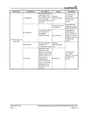
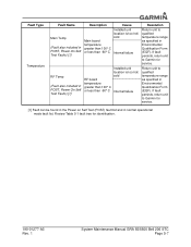
...return unit to Garmin for service. If fault persists, return unit to Garmin for service. Download the assert log and send to unit. Cycle power to Garmin for service. 190-01277-A3 Rev. 1 System Maintenance Manual GRA 55/5500 Bell 206 ...STC Page 5-2 Fault Type Fault Name PLL Register RF Self-Test POST (Power On Self-Test) Sensor Boot Various [1] Description Cause Resolution After programming, read-back of these tests is not within the acceptable frequency range Improper antenna connections Internal failure Check antenna installation...
...return unit to Garmin for service. If fault persists, return unit to Garmin for service. Download the assert log and send to unit. Cycle power to Garmin for service. 190-01277-A3 Rev. 1 System Maintenance Manual GRA 55/5500 Bell 206 ...STC Page 5-2 Fault Type Fault Name PLL Register RF Self-Test POST (Power On Self-Test) Sensor Boot Various [1] Description Cause Resolution After programming, read-back of these tests is not within the acceptable frequency range Improper antenna connections Internal failure Check antenna installation...

Maintenance Manual
Page 32
...there are no assert log entries for service. If fault persists, return unit to Garmin for service. 190-01277-A3 Rev. 1 System Maintenance Manual GRA 55/5500 Bell 206 STC Page 5-6 Check antenna installation and all cable connections. The LO PLL is not locked while the Internal failure ...failure Improper antenna connections The self-test signal is transmitting. If fault persists, download the assert log and send to Garmin for diagnosis. Check antenna installation and all cable connections. Cycle power to unit. Cycle power to unit. If fault persists, download the assert ...
...there are no assert log entries for service. If fault persists, return unit to Garmin for service. 190-01277-A3 Rev. 1 System Maintenance Manual GRA 55/5500 Bell 206 STC Page 5-6 Check antenna installation and all cable connections. The LO PLL is not locked while the Internal failure ...failure Improper antenna connections The self-test signal is transmitting. If fault persists, download the assert log and send to Garmin for diagnosis. Check antenna installation and all cable connections. Cycle power to unit. Cycle power to unit. If fault persists, download the assert ...
Maintenance Manual
Page 33
...included in POST, Power On Self Test Faults) [1] RF Temp (Fault also included in POST, Power On Self Test Faults) [1] Description Cause Installed unit location is too hot/ cold Main board temperature greater than 100° C or less than -60° C Internal failure... on Self Test (POST) fault list and in Environmental Qualification Form (EQF). If fault persists, return unit to Garmin for identification. 190-01277-A3 Rev. 1 System Maintenance Manual GRA 55/5500 Bell 206 STC Page 5-7 If fault persists, return unit to qualified temperature range as specified in normal operational mode ...
...included in POST, Power On Self Test Faults) [1] RF Temp (Fault also included in POST, Power On Self Test Faults) [1] Description Cause Installed unit location is too hot/ cold Main board temperature greater than 100° C or less than -60° C Internal failure... on Self Test (POST) fault list and in Environmental Qualification Form (EQF). If fault persists, return unit to Garmin for identification. 190-01277-A3 Rev. 1 System Maintenance Manual GRA 55/5500 Bell 206 STC Page 5-7 If fault persists, return unit to qualified temperature range as specified in normal operational mode ...

Maintenance Manual
Page 44
REF. COAXIAL CABLE REF. GRA 55/5500 WIRING HARNESS WL 0.00 REF. GRA 55/5500 Wire Routing in the Bell 206B, 206L Series 190-01277-A3 Rev. 1 System Maintenance Manual GRA 55/5500 Bell 206 STC Page A-4 RADAR ALTIMETER ANTENNAS FS 0.00 FS 130.00 FS 142.33 ...22 TBS 71.44 Figure A-5. Figure A-5 depicts the typical wire harness installation for the antennas. For additional details refer to include the coaxial cable installation for the GRA 55/5500 system, to the GRA 55/5500 installation manual. CIRCUIT BREAKER REF. Due to aircraft configurations, minor deviations may exist ...
REF. COAXIAL CABLE REF. GRA 55/5500 WIRING HARNESS WL 0.00 REF. GRA 55/5500 Wire Routing in the Bell 206B, 206L Series 190-01277-A3 Rev. 1 System Maintenance Manual GRA 55/5500 Bell 206 STC Page A-4 RADAR ALTIMETER ANTENNAS FS 0.00 FS 130.00 FS 142.33 ...22 TBS 71.44 Figure A-5. Figure A-5 depicts the typical wire harness installation for the antennas. For additional details refer to include the coaxial cable installation for the GRA 55/5500 system, to the GRA 55/5500 installation manual. CIRCUIT BREAKER REF. Due to aircraft configurations, minor deviations may exist ...

