Maintenance Manual
Page 1
System Maintenance Manual GRA 55/5500 Bell 206 STC Contains Instructions for Continued Airworthiness for Bell 206 STC 190-01277-A3 July 2014 Revision 1
System Maintenance Manual GRA 55/5500 Bell 206 STC Contains Instructions for Continued Airworthiness for Bell 206 STC 190-01277-A3 July 2014 Revision 1
Maintenance Manual
Page 2
S/N Contains Instructions for Continued Airworthiness for Bell 206 STC Dwg. No. System Maintenance Manual GRA 55/5500 Bell 206 STC as installed in Bell 206B, 206L Series Reg. Number: 190-01277-A3 Rev. 1 Garmin International, Inc. 1200 E. 151st Street Olathe, Kansas 66062 USA 190-01277-A3 Rev. 1 System Maintenance Manual GRA 55/5500 Bell 206 STC Page A
S/N Contains Instructions for Continued Airworthiness for Bell 206 STC Dwg. No. System Maintenance Manual GRA 55/5500 Bell 206 STC as installed in Bell 206B, 206L Series Reg. Number: 190-01277-A3 Rev. 1 Garmin International, Inc. 1200 E. 151st Street Olathe, Kansas 66062 USA 190-01277-A3 Rev. 1 System Maintenance Manual GRA 55/5500 Bell 206 STC Page A

Maintenance Manual
Page 3
...Fax: (913) 397-0868 Fax (Toll Free): (800) 801-4670 E-mail: orders@garmin.com avionics@garmin.com warranty@garmin.com Garmin AT, Inc. 2345 Turner Rd. © 2014 Garmin International, Inc. SE Salem, OR 97302 USA Telephone: (503) 581-8101 Telephone (Toll ... or any purpose without the express prior written consent of this guide, please e-mail Techpubs.Salem@garmin.com. Garmin hereby grants permission to download a single copy of this manual and of any revision to this ...Aviation Support +44 (0) 87 0850 1243 190-01277-A3 Rev. 1 System Maintenance Manual GRA 55/5500 Bell 206 STC Page B
...Fax: (913) 397-0868 Fax (Toll Free): (800) 801-4670 E-mail: orders@garmin.com avionics@garmin.com warranty@garmin.com Garmin AT, Inc. 2345 Turner Rd. © 2014 Garmin International, Inc. SE Salem, OR 97302 USA Telephone: (503) 581-8101 Telephone (Toll ... or any purpose without the express prior written consent of this guide, please e-mail Techpubs.Salem@garmin.com. Garmin hereby grants permission to download a single copy of this manual and of any revision to this ...Aviation Support +44 (0) 87 0850 1243 190-01277-A3 Rev. 1 System Maintenance Manual GRA 55/5500 Bell 206 STC Page B
Maintenance Manual
Page 4
... 5 Section 6 Section 7 Section 8 Section 9 Appendix A Pagination ii through v 1-1 through 1-2 2-1 through 2-1 3-1 through 3-8 4-1 through 4-6 5-1 through 5-7 6-1 through 6-3 7-1 through 7-1 8-1 through 8-2 9-1 through 9-1 A-1 through A-7 190-01277-A3 Rev. 1 System Maintenance Manual GRA 55/5500 Bell 206 STC Page C
... 5 Section 6 Section 7 Section 8 Section 9 Appendix A Pagination ii through v 1-1 through 1-2 2-1 through 2-1 3-1 through 3-8 4-1 through 4-6 5-1 through 5-7 6-1 through 6-3 7-1 through 7-1 8-1 through 8-2 9-1 through 9-1 A-1 through A-7 190-01277-A3 Rev. 1 System Maintenance Manual GRA 55/5500 Bell 206 STC Page C
Maintenance Manual
Page 5
... further understanding of the reason for current updates and supplemental information concerning the operation of Garmin products. Visit the Garmin web site (www.garmin.com) for the particular operation. 190-01277-A3 Rev. 1 System Maintenance Manual GRA 55/5500 Bell 206 STC Page i DEFINITIONS OF WARNINGS, CAUTIONS, AND NOTES WARNING Warnings are used to the equipment...
... further understanding of the reason for current updates and supplemental information concerning the operation of Garmin products. Visit the Garmin web site (www.garmin.com) for the particular operation. 190-01277-A3 Rev. 1 System Maintenance Manual GRA 55/5500 Bell 206 STC Page i DEFINITIONS OF WARNINGS, CAUTIONS, AND NOTES WARNING Warnings are used to the equipment...

Maintenance Manual
Page 6
...of Alteration ...2-1 2.2 Block Diagram ...2-1 3 GRA 55/5500 CONTROL AND OPERATION 3-1 3.1 Control, Operating, and Testing Information 3-1 3.2 Downloading and Installing the GRA 55/5500 Retrofit Installation Tool 3-1 3.3 Using the GRA 55/5500 Retrofit Installation Tool 3-2 3.4 Installation Tool ... Information ...4-1 4.2 Periodic Maintenance ...4-1 4.3 Special Tools ...4-1 4.4 Maintenance Intervals ...4-2 5 TROUBLESHOOTING INFORMATION 5-1 5.1 GRA 55/5500 General Troubleshooting 5-1 6 REMOVAL AND REPLACEMENT INFORMATION 6-1 6.1 Unit Installation ...6-1 6.1.1 Installation Procedure 6-1 6.1.2...
...of Alteration ...2-1 2.2 Block Diagram ...2-1 3 GRA 55/5500 CONTROL AND OPERATION 3-1 3.1 Control, Operating, and Testing Information 3-1 3.2 Downloading and Installing the GRA 55/5500 Retrofit Installation Tool 3-1 3.3 Using the GRA 55/5500 Retrofit Installation Tool 3-2 3.4 Installation Tool ... Information ...4-1 4.2 Periodic Maintenance ...4-1 4.3 Special Tools ...4-1 4.4 Maintenance Intervals ...4-2 5 TROUBLESHOOTING INFORMATION 5-1 5.1 GRA 55/5500 General Troubleshooting 5-1 6 REMOVAL AND REPLACEMENT INFORMATION 6-1 6.1 Unit Installation ...6-1 6.1.1 Installation Procedure 6-1 6.1.2...
Maintenance Manual
Page 7
... Revision and Distribution 8-1 8.8 Assistance ...8-1 8.9 Implementation and Record Keeping 8-2 9 AIRWORTHINESS LIMITATIONS SECTION 9-1 APPENDIX A AIRCRAFT SPECIFIC INFORMATION A-1 A.1 Weight and Balance ...A-5 190-01277-A3 Rev. 1 System Maintenance Manual GRA 55/5500 Bell 206 STC Page iii
... Revision and Distribution 8-1 8.8 Assistance ...8-1 8.9 Implementation and Record Keeping 8-2 9 AIRWORTHINESS LIMITATIONS SECTION 9-1 APPENDIX A AIRCRAFT SPECIFIC INFORMATION A-1 A.1 Weight and Balance ...A-5 190-01277-A3 Rev. 1 System Maintenance Manual GRA 55/5500 Bell 206 STC Page iii

Maintenance Manual
Page 8
..., 206L Series A-3 GRA 55/5500 Wire Routing in the Bell 206B, 206L Series A-4 GRA 55/5500 Unit Location and...GRA 55/5500 Bell 206 STC Page iv Figure 2-1. Figure A-5. Figure A-1. LIST OF FIGURES GRA 55/5500 Block Diagram 2-1 Installation Tool Page Tabs 3-2 Status Page ...3-3 Configuration Page 3-4 Software Page ...3-5 Diagnostics Page 3-6 Utilities Page ...3-7 GRA 55/5500 Installation 6-2 Rack Installation 6-3 GRA 55/5500 Antenna Installation 6-3 GRA STC Equipment Fuselage Station Location for Bell 206 A-1 GRA STC Equipment Fuselage Station Location for Bell 206L Series A-1 GRA 55...
..., 206L Series A-3 GRA 55/5500 Wire Routing in the Bell 206B, 206L Series A-4 GRA 55/5500 Unit Location and...GRA 55/5500 Bell 206 STC Page iv Figure 2-1. Figure A-5. Figure A-1. LIST OF FIGURES GRA 55/5500 Block Diagram 2-1 Installation Tool Page Tabs 3-2 Status Page ...3-3 Configuration Page 3-4 Software Page ...3-5 Diagnostics Page 3-6 Utilities Page ...3-7 GRA 55/5500 Installation 6-2 Rack Installation 6-3 GRA 55/5500 Antenna Installation 6-3 GRA STC Equipment Fuselage Station Location for Bell 206 A-1 GRA STC Equipment Fuselage Station Location for Bell 206L Series A-1 GRA 55...
Maintenance Manual
Page 9
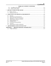
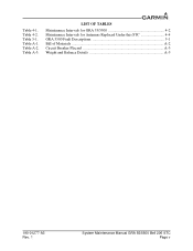
Table A-2. Table 4-2. Table 4-1. Table 5-1. Table A-3. Table A-1. LIST OF TABLES Maintenance Intervals for GRA 55/5500 4-2 Maintenance Intervals for Antennas Replaced Under this STC 4-4 GRA 5500 Fault Descriptions 5-1 Bill of Materials A-2 Circuit Breaker Placard A-3 Weight and Balance Details A-5 190-01277-A3 Rev. 1 System Maintenance Manual GRA 55/5500 Bell 206 STC Page v
Table A-2. Table 4-2. Table 4-1. Table 5-1. Table A-3. Table A-1. LIST OF TABLES Maintenance Intervals for GRA 55/5500 4-2 Maintenance Intervals for Antennas Replaced Under this STC 4-4 GRA 5500 Fault Descriptions 5-1 Bill of Materials A-2 Circuit Breaker Placard A-3 Weight and Balance Details A-5 190-01277-A3 Rev. 1 System Maintenance Manual GRA 55/5500 Bell 206 STC Page v

Maintenance Manual
Page 10
... This document provides Instructions for Continued Airworthiness for the Bell 206B, 206L, L-1, L-3, and L-4 rotorcraft, modified by the agency installing the Garmin GRA 55/5500 radar altimeter system under the GRA 55/5500 STC. ACO:Aircraft Certification Office 2. CFR:Code of the documents. PMI:Principal Maintenance Inspector 14. This permission does not construe suitability of Federal Regulations...
... This document provides Instructions for Continued Airworthiness for the Bell 206B, 206L, L-1, L-3, and L-4 rotorcraft, modified by the agency installing the Garmin GRA 55/5500 radar altimeter system under the GRA 55/5500 STC. ACO:Aircraft Certification Office 2. CFR:Code of the documents. PMI:Principal Maintenance Inspector 14. This permission does not construe suitability of Federal Regulations...

Maintenance Manual
Page 11
..., 1 June 2012 6. Electrical Standard Practices Manual for the modification of the aircraft by the installation of the Garmin GRA 55/5500 Part 27 STC. 1.7.1 Applicability Applies to aircraft altered by the installation of the Garmin GRA 55/5500 Part 27 STC. 1.7.2 Definition of Abbreviations See Section 1.5 and Section 1.6. 1.7.3 Precautions None. 1.7.4 Units of measurement None. 1.7.5 Referenced publications (or their...
..., 1 June 2012 6. Electrical Standard Practices Manual for the modification of the aircraft by the installation of the Garmin GRA 55/5500 Part 27 STC. 1.7.1 Applicability Applies to aircraft altered by the installation of the Garmin GRA 55/5500 Part 27 STC. 1.7.2 Definition of Abbreviations See Section 1.5 and Section 1.6. 1.7.3 Precautions None. 1.7.4 Units of measurement None. 1.7.5 Referenced publications (or their...

Maintenance Manual
Page 12
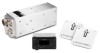
... rack that is electrically bonded to the avionics shelf. GRA 55/5500 Block Diagram System Maintenance Manual GRA 55/5500 Bell 206 STC Page 2-1 The GRA 55/5500 radar altimeter system features: two antenna architecture for transmitting... and receiving radio waves for altitude quantities, remote mounted LRU transceiver for pilot display of aircraft altitude and system degraded warnings. The two approved radar altimeter antennas are compatible with an installed Garmin...
... rack that is electrically bonded to the avionics shelf. GRA 55/5500 Block Diagram System Maintenance Manual GRA 55/5500 Bell 206 STC Page 2-1 The GRA 55/5500 radar altimeter system features: two antenna architecture for transmitting... and receiving radio waves for altitude quantities, remote mounted LRU transceiver for pilot display of aircraft altitude and system degraded warnings. The two approved radar altimeter antennas are compatible with an installed Garmin...

Maintenance Manual
Page 13
...close the setup wizard. 190-01277-A3 Rev. 1 System Maintenance Manual GRA 55/5500 Bell 206 STC Page 3-1 Click "Next" as needed. 4. 3 GRA 55/5500 CONTROL AND OPERATION 3.1 Control, Operating, and Testing Information The GRA 55/5500 is cycled and subsequently every minute during "No Computed Data" ... upgrades are performed using a personal computer (installed with Microsoft Windows XP Service Pack 3 or later) and the GRA 55/5500 Retrofit Installation Tool, Garmin part number 006-A0451-00. See the accompanying "readme" file in the wiring harness. Installation 1. The last screen...
...close the setup wizard. 190-01277-A3 Rev. 1 System Maintenance Manual GRA 55/5500 Bell 206 STC Page 3-1 Click "Next" as needed. 4. 3 GRA 55/5500 CONTROL AND OPERATION 3.1 Control, Operating, and Testing Information The GRA 55/5500 is cycled and subsequently every minute during "No Computed Data" ... upgrades are performed using a personal computer (installed with Microsoft Windows XP Service Pack 3 or later) and the GRA 55/5500 Retrofit Installation Tool, Garmin part number 006-A0451-00. See the accompanying "readme" file in the wiring harness. Installation 1. The last screen...
Maintenance Manual
Page 14
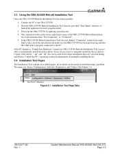
... the PC displays a "Found New Hardware" wizard, the GRA 55/5500 Retrofit Installation Tool was not able to the GRA 55/5500 2. Figure 3-1. Installation Tool Page Tabs 190-01277-A3 Rev. 1 System Maintenance Manual GRA 55/5500 Bell 206 STC Page 3-2 3.3 Using the GRA 55/5500 Retrofit Installation Tool Once the GRA 55/5500 Retrofit Installation Tool has been installed: 1. Consult...
... the PC displays a "Found New Hardware" wizard, the GRA 55/5500 Retrofit Installation Tool was not able to the GRA 55/5500 2. Figure 3-1. Installation Tool Page Tabs 190-01277-A3 Rev. 1 System Maintenance Manual GRA 55/5500 Bell 206 STC Page 3-2 3.3 Using the GRA 55/5500 Retrofit Installation Tool Once the GRA 55/5500 Retrofit Installation Tool has been installed: 1. Consult...
Maintenance Manual
Page 15
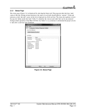
...fault, the fault's entry on the list is displayed by selecting the Status tab. Status Page 190-01277-A3 Rev. 1 System Maintenance Manual GRA 55/5500 Bell 206 STC Page 3-3 Table 5-1 identifies the various unit faults that fault. Figure 3-2. 3.4.1 Status Page The status page (Figure 3-2) is displayed in a... to determine the proper actions to show the specific failure under that can be encountered during normal operation of the GRA 55/5500. During normal operation, the status of the unit. This page provides the basic fault status of each fault should indicate "normal."...
...fault, the fault's entry on the list is displayed by selecting the Status tab. Status Page 190-01277-A3 Rev. 1 System Maintenance Manual GRA 55/5500 Bell 206 STC Page 3-3 Table 5-1 identifies the various unit faults that fault. Figure 3-2. 3.4.1 Status Page The status page (Figure 3-2) is displayed in a... to determine the proper actions to show the specific failure under that can be encountered during normal operation of the GRA 55/5500. During normal operation, the status of the unit. This page provides the basic fault status of each fault should indicate "normal."...
Maintenance Manual
Page 16
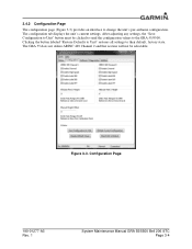
... section will not be clicked to send the configuration values to Unit" button must be selectable. Configuration Page 190-01277-A3 Rev. 1 System Maintenance Manual GRA 55/5500 Bell 206 STC Page 3-4 The configuration tab displays the unit's current settings. Figure 3-3. After adjusting any settings, the "Save Configuration to the...
... section will not be clicked to send the configuration values to Unit" button must be selectable. Configuration Page 190-01277-A3 Rev. 1 System Maintenance Manual GRA 55/5500 Bell 206 STC Page 3-4 The configuration tab displays the unit's current settings. Figure 3-3. After adjusting any settings, the "Save Configuration to the...
Maintenance Manual
Page 17
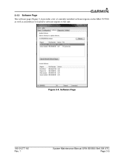
Software Page 190-01277-A3 Rev. 1 System Maintenance Manual GRA 55/5500 Bell 206 STC Page 3-5 3.4.3 Software Page The software page (Figure 3-4) provides a list of currently installed software regions on the GRA 55/5500 as well as an interface to load new software regions to the unit. Figure 3-4.
Software Page 190-01277-A3 Rev. 1 System Maintenance Manual GRA 55/5500 Bell 206 STC Page 3-5 3.4.3 Software Page The software page (Figure 3-4) provides a list of currently installed software regions on the GRA 55/5500 as well as an interface to load new software regions to the unit. Figure 3-4.

Maintenance Manual
Page 18
... for further diagnostic evaluation). Diagnostics Page 190-01277-A3 Rev. 1 System Maintenance Manual GRA 55/5500 Bell 206 STC Page 3-6 This will be selectable. The raw log option will only be disabled. These two buttons will be used to Garmin Engineering. In normal condition, there should be no logged asserts and this page will...
... for further diagnostic evaluation). Diagnostics Page 190-01277-A3 Rev. 1 System Maintenance Manual GRA 55/5500 Bell 206 STC Page 3-6 This will be selectable. The raw log option will only be disabled. These two buttons will be used to Garmin Engineering. In normal condition, there should be no logged asserts and this page will...
Maintenance Manual
Page 19
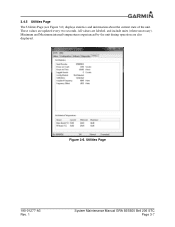
Utilities Page 190-01277-A3 Rev. 1 System Maintenance Manual GRA 55/5500 Bell 206 STC Page 3-7 Figure 3-6. 3.4.5 Utilities Page The Utilities Page (see Figure 3-6) displays statistics and information about the current state of the unit. All values are updated every two seconds. These values are labeled, and include units (where necessary). Minimum and Maximum internal temperatures experienced by the unit during operation are also displayed.
Utilities Page 190-01277-A3 Rev. 1 System Maintenance Manual GRA 55/5500 Bell 206 STC Page 3-7 Figure 3-6. 3.4.5 Utilities Page The Utilities Page (see Figure 3-6) displays statistics and information about the current state of the unit. All values are updated every two seconds. These values are labeled, and include units (where necessary). Minimum and Maximum internal temperatures experienced by the unit during operation are also displayed.
Maintenance Manual
Page 20
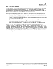
... and mounted in the status bar area indicates "0 ft" and "Normal," the unit has been successfully calibrated. 190-01277-A3 Rev. 1 System Maintenance Manual GRA 55/5500 Bell 206 STC Page 3-8 During the calibration procedure, the GRA 55/5500 Retrofit Installation Tool will report progress updates next to initiate the zero-foot calibration procedure. The...
... and mounted in the status bar area indicates "0 ft" and "Normal," the unit has been successfully calibrated. 190-01277-A3 Rev. 1 System Maintenance Manual GRA 55/5500 Bell 206 STC Page 3-8 During the calibration procedure, the GRA 55/5500 Retrofit Installation Tool will report progress updates next to initiate the zero-foot calibration procedure. The...

