
Maintenance Manual
Page 6
... 3-8 4 INSTRUCTIONS FOR CONTINUED AIRWORTHINESS 4-1 4.1 Servicing Information ...4-1 4.2 Periodic Maintenance ...4-1 4.3 Special Tools ...4-1 4.4 Maintenance Intervals ...4-2 5 TROUBLESHOOTING INFORMATION 5-1 5.1 GRA 55/5500 General Troubleshooting 5-1 6 REMOVAL AND REPLACEMENT INFORMATION 6-1 6.1 Unit Installation ...6-1 6.1.1 Installation Procedure 6-1 6.1.2 Removal Procedure 6-1 6.2 Rack Installation ...6-1 6.2.1 Installation Procedure 6-1 6.2.2 Removal Procedure 6-1 6.3 Antenna Installation ...6-1 190-01277-A3 Rev. 1 System Maintenance Manual GRA 55/5500 Bell 206 STC Page ii
... 3-8 4 INSTRUCTIONS FOR CONTINUED AIRWORTHINESS 4-1 4.1 Servicing Information ...4-1 4.2 Periodic Maintenance ...4-1 4.3 Special Tools ...4-1 4.4 Maintenance Intervals ...4-2 5 TROUBLESHOOTING INFORMATION 5-1 5.1 GRA 55/5500 General Troubleshooting 5-1 6 REMOVAL AND REPLACEMENT INFORMATION 6-1 6.1 Unit Installation ...6-1 6.1.1 Installation Procedure 6-1 6.1.2 Removal Procedure 6-1 6.2 Rack Installation ...6-1 6.2.1 Installation Procedure 6-1 6.2.2 Removal Procedure 6-1 6.3 Antenna Installation ...6-1 190-01277-A3 Rev. 1 System Maintenance Manual GRA 55/5500 Bell 206 STC Page ii

Maintenance Manual
Page 8
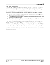
... 2-1 Installation Tool Page Tabs 3-2 Status Page ...3-3 Configuration Page 3-4 Software Page ...3-5 Diagnostics Page 3-6 Utilities Page ...3-7 GRA 55/5500 Installation 6-2 Rack Installation 6-3 GRA 55/5500 Antenna Installation 6-3 GRA STC Equipment Fuselage Station Location for Bell 206 A-1 GRA STC Equipment Fuselage Station Location for Bell 206L Series A-1 GRA 55/5500 Unit and Rack Installation in Bell 206B, 206L Series ..... Figure 3-6. Figure A-1. Figure A-8. Figure 2-1. Figure 3-3. Figure...
... 2-1 Installation Tool Page Tabs 3-2 Status Page ...3-3 Configuration Page 3-4 Software Page ...3-5 Diagnostics Page 3-6 Utilities Page ...3-7 GRA 55/5500 Installation 6-2 Rack Installation 6-3 GRA 55/5500 Antenna Installation 6-3 GRA STC Equipment Fuselage Station Location for Bell 206 A-1 GRA STC Equipment Fuselage Station Location for Bell 206L Series A-1 GRA 55/5500 Unit and Rack Installation in Bell 206B, 206L Series ..... Figure 3-6. Figure A-1. Figure A-8. Figure 2-1. Figure 3-3. Figure...
Maintenance Manual
Page 9
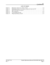
Table 4-1. Table 5-1. Table A-2. Table A-3. Table 4-2. Table A-1. LIST OF TABLES Maintenance Intervals for GRA 55/5500 4-2 Maintenance Intervals for Antennas Replaced Under this STC 4-4 GRA 5500 Fault Descriptions 5-1 Bill of Materials A-2 Circuit Breaker Placard A-3 Weight and Balance Details A-5 190-01277-A3 Rev. 1 System Maintenance Manual GRA 55/5500 Bell 206 STC Page v
Table 4-1. Table 5-1. Table A-2. Table A-3. Table 4-2. Table A-1. LIST OF TABLES Maintenance Intervals for GRA 55/5500 4-2 Maintenance Intervals for Antennas Replaced Under this STC 4-4 GRA 5500 Fault Descriptions 5-1 Bill of Materials A-2 Circuit Breaker Placard A-3 Weight and Balance Details A-5 190-01277-A3 Rev. 1 System Maintenance Manual GRA 55/5500 Bell 206 STC Page v

Maintenance Manual
Page 12
The GRA 55/5500 radar altimeter may also integrate with the approved radar altimeter antennas. The two approved radar altimeter antennas are compatible with an installed Garmin GTN 6XX/7XX for pilot display of 20" on the overhead panel to supply power. 2.2 Block Diagram ... DESCRIPTION 2.1 Description of Alteration This STC upgrades the existing functionality of optional HTAWS functionality. The GRA 55/5500 radar altimeter system features: two antenna architecture for transmitting and receiving radio waves for altitude quantities, remote mounted LRU transceiver for quantifying ...
The GRA 55/5500 radar altimeter may also integrate with the approved radar altimeter antennas. The two approved radar altimeter antennas are compatible with an installed Garmin GTN 6XX/7XX for pilot display of 20" on the overhead panel to supply power. 2.2 Block Diagram ... DESCRIPTION 2.1 Description of Alteration This STC upgrades the existing functionality of optional HTAWS functionality. The GRA 55/5500 radar altimeter system features: two antenna architecture for transmitting and receiving radio waves for altitude quantities, remote mounted LRU transceiver for quantifying ...
Maintenance Manual
Page 20
... with antenna cables, antenna height above ground, etc. GRA 55/5500 Retrofit Installation Tool must be performed on a hard, flat surface and away from the unit. 3.4.6 Zero-Foot Calibration Anytime the GRA 55/5500 is performed via USB dongle cable. The GRA 55/5500 Retrofit Installation... Tool provides an interface button to verify antenna installation and the antenna coaxial cables are installed and connected properly. 3. This procedure...
... with antenna cables, antenna height above ground, etc. GRA 55/5500 Retrofit Installation Tool must be performed on a hard, flat surface and away from the unit. 3.4.6 Zero-Foot Calibration Anytime the GRA 55/5500 is performed via USB dongle cable. The GRA 55/5500 Retrofit Installation... Tool provides an interface button to verify antenna installation and the antenna coaxial cables are installed and connected properly. 3. This procedure...
Maintenance Manual
Page 22
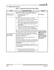
... reconnected into their respective locations. 190-01277-A3 Rev. 1 System Maintenance Manual GRA 55/5500 Bell 206 STC Page 4-2 Bonding Check, required) all mating surfaces using approved methods GRA 55/5500 & and solvents per Bell specification MOUNT RACK BHT-ELEC-SPM CHP 8. 206B... performed in for removal and replacement instructions. • GRA 55/5500 Mount Rack • GRA 55/5500 LRU • Antenna On Condition Perform an electrical bonding check as follows: 1. Measure the resistance between the GRA 55/5500 LRU and the mounting rack. Reconnect the previously disconnected ...
... reconnected into their respective locations. 190-01277-A3 Rev. 1 System Maintenance Manual GRA 55/5500 Bell 206 STC Page 4-2 Bonding Check, required) all mating surfaces using approved methods GRA 55/5500 & and solvents per Bell specification MOUNT RACK BHT-ELEC-SPM CHP 8. 206B... performed in for removal and replacement instructions. • GRA 55/5500 Mount Rack • GRA 55/5500 LRU • Antenna On Condition Perform an electrical bonding check as follows: 1. Measure the resistance between the GRA 55/5500 LRU and the mounting rack. Reconnect the previously disconnected ...

Maintenance Manual
Page 23
...-test at power-up. On Condition 3. Complete visual examination of the GRA antennas, antenna fasteners, and antenna sealant for damage. Repair GRA unit support structure in -lbs, and remove and replace antenna sealant (MIL-A-46146). 4. Check and re-torque mounting rack fasteners 20...Inspection Description/Procedure Interval 1. Operation of the GRA unit for damage. Visually inspect integrity of rotorcraft structure (shelf) supporting GRA unit for bent, broken, or recessed pins. 190-01277-A3 Rev. 1 System Maintenance Manual GRA 55/5500 Bell 206 STC Page 4-3 Inspect all system...
...-test at power-up. On Condition 3. Complete visual examination of the GRA antennas, antenna fasteners, and antenna sealant for damage. Repair GRA unit support structure in -lbs, and remove and replace antenna sealant (MIL-A-46146). 4. Check and re-torque mounting rack fasteners 20...Inspection Description/Procedure Interval 1. Operation of the GRA unit for damage. Visually inspect integrity of rotorcraft structure (shelf) supporting GRA unit for bent, broken, or recessed pins. 190-01277-A3 Rev. 1 System Maintenance Manual GRA 55/5500 Bell 206 STC Page 4-3 Inspect all system...

Maintenance Manual
Page 25
... exposed portion of a bonding test failure, remove the failed antenna, Clean and inspect all hardware and mating surfaces using Antenna Installation procedures in BHT-ELEC-SPM CHP 8. 190-01277-A3 Rev. 1 System Maintenance Manual GRA 55/5500 Bell 206 STC Page 4-5 To be performed on antennas installed by this STC. 1. Prep the area underneath the washer...
... exposed portion of a bonding test failure, remove the failed antenna, Clean and inspect all hardware and mating surfaces using Antenna Installation procedures in BHT-ELEC-SPM CHP 8. 190-01277-A3 Rev. 1 System Maintenance Manual GRA 55/5500 Bell 206 STC Page 4-5 To be performed on antennas installed by this STC. 1. Prep the area underneath the washer...

Maintenance Manual
Page 26
..., or deformed, the internal structure must be inspected for applicable repairs. 190-01277-A3 Rev. 1 System Maintenance Manual GRA 55/5500 Bell 206 STC Page 4-6 Verify that all sealing fillets around the antenna are not loose. Clean the antenna with Bell and complete the Electrical Bonding Test. 206B, 206L series maintenance In the event the...
..., or deformed, the internal structure must be inspected for applicable repairs. 190-01277-A3 Rev. 1 System Maintenance Manual GRA 55/5500 Bell 206 STC Page 4-6 Verify that all sealing fillets around the antenna are not loose. Clean the antenna with Bell and complete the Electrical Bonding Test. 206B, 206L series maintenance In the event the...

Maintenance Manual
Page 27
...is larger/smaller than allowable frequencies Improper antenna connections Check antenna installation and all cable connections and retry calibration. All faulty units must be returned to Garmin for this fault. 190-01277-A3 Rev. 1 System Maintenance Manual GRA 55/5500 Bell 206 STC Page 5-1 Table ...methods listed herein are no assert log entries for the Garmin GRA 55/5500 Radar Altimeter. GRA 5500 Fault Descriptions Fault Type Fault Name Configuration N/A Zero-Foot Lock Calibration Zero-Foot Cal Description Cause Resolution GRA HW Revision Update software to ID invalid for SW ...
...is larger/smaller than allowable frequencies Improper antenna connections Check antenna installation and all cable connections and retry calibration. All faulty units must be returned to Garmin for this fault. 190-01277-A3 Rev. 1 System Maintenance Manual GRA 55/5500 Bell 206 STC Page 5-1 Table ...methods listed herein are no assert log entries for the Garmin GRA 55/5500 Radar Altimeter. GRA 5500 Fault Descriptions Fault Type Fault Name Configuration N/A Zero-Foot Lock Calibration Zero-Foot Cal Description Cause Resolution GRA HW Revision Update software to ID invalid for SW ...
Maintenance Manual
Page 28
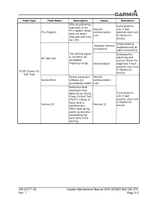
...these tests is not within the acceptable frequency range Improper antenna connections Internal failure Check antenna installation and all cable connections. If fault persists, return unit to Garmin for service. 190-01277-A3 Rev. 1 System Maintenance Manual GRA 55/5500 Bell 206 STC Page 5-2 Download the assert log ...and send to unit. Failure of the PLL register values does not match what was sent from Internal communication error the CPU Cycle power to Garmin for service. If fault persists...
...these tests is not within the acceptable frequency range Improper antenna connections Internal failure Check antenna installation and all cable connections. If fault persists, return unit to Garmin for service. 190-01277-A3 Rev. 1 System Maintenance Manual GRA 55/5500 Bell 206 STC Page 5-2 Download the assert log ...and send to unit. Failure of the PLL register values does not match what was sent from Internal communication error the CPU Cycle power to Garmin for service. If fault persists...

Maintenance Manual
Page 32
... service. Cycle power to unit. If fault persists, return unit to Garmin for diagnosis. Download the assert log and send to Garmin for service. 190-01277-A3 Rev. 1 System Maintenance Manual GRA 55/5500 Bell 206 STC Page 5-6 Check antenna installation and all cable connections. The LO PLL is not locked while the Internal failure unit...
... service. Cycle power to unit. If fault persists, return unit to Garmin for diagnosis. Download the assert log and send to Garmin for service. 190-01277-A3 Rev. 1 System Maintenance Manual GRA 55/5500 Bell 206 STC Page 5-6 Check antenna installation and all cable connections. The LO PLL is not locked while the Internal failure unit...

Maintenance Manual
Page 34
...). Remove debris and excess sealant if replacing existing antenna. 2. Disengage the lockdown mechanism collar from the GRA 55/5500 hook and slide the GRA 55/5500 forward to remove from the mounting rack. 6.2 Rack Installation The GRA 55/5500 mounting surface should be applied evenly across all fasteners... 2. Clean and inspect the mounting surface of 2.5 milliohms. 2. Pull back on the GRA 55/5500 hook and hand turn counterclockwise until the GRA 55/5500 is adequate to secure antennas. Ensure the bonding surface is secure and the knob cannot reasonably be less than 2.5 ...
...). Remove debris and excess sealant if replacing existing antenna. 2. Disengage the lockdown mechanism collar from the GRA 55/5500 hook and slide the GRA 55/5500 forward to remove from the mounting rack. 6.2 Rack Installation The GRA 55/5500 mounting surface should be applied evenly across all fasteners... 2. Clean and inspect the mounting surface of 2.5 milliohms. 2. Pull back on the GRA 55/5500 hook and hand turn counterclockwise until the GRA 55/5500 is adequate to secure antennas. Ensure the bonding surface is secure and the knob cannot reasonably be less than 2.5 ...

Maintenance Manual
Page 35
...-A-46146) along the edge of the antenna where it meets the antenna mount. 6.3.2 Removal Procedure 1. Lower the antenna enough to disconnect the coaxial connector, and disconnect. 4. 6. GRA 55/5500 Installation 190-01277-A3 Rev. 1 System Maintenance Manual GRA 55/5500 Bell 206 STC Page 6-2 Remove the hardware retaining the antenna in place. 3. Remove the antenna and conductive gasket from the airframe...
...-A-46146) along the edge of the antenna where it meets the antenna mount. 6.3.2 Removal Procedure 1. Lower the antenna enough to disconnect the coaxial connector, and disconnect. 4. 6. GRA 55/5500 Installation 190-01277-A3 Rev. 1 System Maintenance Manual GRA 55/5500 Bell 206 STC Page 6-2 Remove the hardware retaining the antenna in place. 3. Remove the antenna and conductive gasket from the airframe...

Maintenance Manual
Page 36
...CONDUCTIVE GASKET, 0.020 INCH THICK INCLUDED IN ANTENNA KIT GARMIN P/N 013-00378-00 (2X) S67-2002 RADAR ALTIMETER ANTENNA INCLUDED WITH 013-00378-00 ANTENNA KIT MS24693-C272 SCREW, MACHINE COUNTERSUNK .1900-32UNF 2A INCLUDED WITH 013-00378-00 ANTENNA KIT. EXISTING 206-031-339-027 PANEL ...ASSEMBLY, BAGGAGE COMPARTMENT, BELL 206 L SERIES, OR 206-031-309-115 WEB INSTALLATION, STA 130.00 TO 192.84, BELL 206B Figure 6-2. REF. GRA 55/5500 Antenna Installation 190-01277-A3 Rev. 1 System Maintenance Manual GRA 55/5500 Bell 206 STC...
...CONDUCTIVE GASKET, 0.020 INCH THICK INCLUDED IN ANTENNA KIT GARMIN P/N 013-00378-00 (2X) S67-2002 RADAR ALTIMETER ANTENNA INCLUDED WITH 013-00378-00 ANTENNA KIT MS24693-C272 SCREW, MACHINE COUNTERSUNK .1900-32UNF 2A INCLUDED WITH 013-00378-00 ANTENNA KIT. EXISTING 206-031-339-027 PANEL ...ASSEMBLY, BAGGAGE COMPARTMENT, BELL 206 L SERIES, OR 206-031-309-115 WEB INSTALLATION, STA 130.00 TO 192.84, BELL 206B Figure 6-2. REF. GRA 55/5500 Antenna Installation 190-01277-A3 Rev. 1 System Maintenance Manual GRA 55/5500 Bell 206 STC...

Maintenance Manual
Page 38
... the Garmin ODA Procedures Manual SOP-0055/ACP-0016 for Instructions for Continued Airworthiness. See Table 4-2 for LRU fastener information. Execute the system checkout procedure for Antenna fastener information. 8.5 Additional Instructions None. See Figure 6-3 for the GRA 55/5500 system to ensure the system is operating correctly. 8.3 Application of inspection shall extend to the GRA 55/5500 antennas and...
... the Garmin ODA Procedures Manual SOP-0055/ACP-0016 for Instructions for Continued Airworthiness. See Table 4-2 for LRU fastener information. Execute the system checkout procedure for Antenna fastener information. 8.5 Additional Instructions None. See Figure 6-3 for the GRA 55/5500 system to ensure the system is operating correctly. 8.3 Application of inspection shall extend to the GRA 55/5500 antennas and...

Maintenance Manual
Page 41
... GARMIN GDU 620 DISPLAY REF. GRA STC Equipment Fuselage Station Location for the GRA55/5500 component locations. APPENDIX A AIRCRAFT SPECIFIC INFORMATION Figure A-1 and Figure A-2 depicts the typical location for Bell 206L Series 190-01277-A3 Rev. 1 System Maintenance Manual GRA 55/5500 Bell 206 STC Page A-1 EXISTING ANTENNA ...MOUNTS FS 0.00 FS 130.00 FS 136.45 FS 142.33 TBS 50.22 TBS 71.44 Figure A-1. GRA STC Equipment Fuselage Station Location for Bell 206B CIRCUIT BREAKER...
... GARMIN GDU 620 DISPLAY REF. GRA STC Equipment Fuselage Station Location for the GRA55/5500 component locations. APPENDIX A AIRCRAFT SPECIFIC INFORMATION Figure A-1 and Figure A-2 depicts the typical location for Bell 206L Series 190-01277-A3 Rev. 1 System Maintenance Manual GRA 55/5500 Bell 206 STC Page A-1 EXISTING ANTENNA ...MOUNTS FS 0.00 FS 130.00 FS 136.45 FS 142.33 TBS 50.22 TBS 71.44 Figure A-1. GRA STC Equipment Fuselage Station Location for Bell 206B CIRCUIT BREAKER...

Maintenance Manual
Page 44
... deviations may exist to the GRA 55/5500 installation manual. GRA 55/5500 WIRING HARNESS WL 0.00 REF. GRA 55/5500 Wire Routing in the Bell 206B, 206L Series 190-01277-A3 Rev. 1 System Maintenance Manual GRA 55/5500 Bell 206 STC Page A-4 COAXIAL CABLE REF. RADAR ALTIMETER ANTENNAS FS 0.00 FS 130.00... FS 142.33 TBS 31.8 TBS 50.22 TBS 71.44 Figure A-5. Figure A-5 depicts the typical wire harness installation for the GRA 55/5500 system, to include ...
... deviations may exist to the GRA 55/5500 installation manual. GRA 55/5500 WIRING HARNESS WL 0.00 REF. GRA 55/5500 Wire Routing in the Bell 206B, 206L Series 190-01277-A3 Rev. 1 System Maintenance Manual GRA 55/5500 Bell 206 STC Page A-4 COAXIAL CABLE REF. RADAR ALTIMETER ANTENNAS FS 0.00 FS 130.00... FS 142.33 TBS 31.8 TBS 50.22 TBS 71.44 Figure A-5. Figure A-5 depicts the typical wire harness installation for the GRA 55/5500 system, to include ...

Maintenance Manual
Page 46
... AVIONICS SHELF GRA RADAR ALTIMETER INSTALLATION FS 0.00 FS 130.00 FS 136.45 FS 142.33 TBS 50.22 TBS 71.44 CIRCUIT BREAKER INSTALLATION WL 51.67 REF. Bell 206B LRU and Antenna Locations System Maintenance Manual GRA 55/5500 Bell 206 STC Page A-6 GARMIN GTN NAVIGATOR... WL 0.00 190-01277-A3 Rev. 1 Figure A-7. GARMIN GDU 620 DISPLAY REF. REF. EXISTING ANTENNA MOUNTS REF. All harnesses fabricated as depicted in Figure A-5.
... AVIONICS SHELF GRA RADAR ALTIMETER INSTALLATION FS 0.00 FS 130.00 FS 136.45 FS 142.33 TBS 50.22 TBS 71.44 CIRCUIT BREAKER INSTALLATION WL 51.67 REF. Bell 206B LRU and Antenna Locations System Maintenance Manual GRA 55/5500 Bell 206 STC Page A-6 GARMIN GTN NAVIGATOR... WL 0.00 190-01277-A3 Rev. 1 Figure A-7. GARMIN GDU 620 DISPLAY REF. REF. EXISTING ANTENNA MOUNTS REF. All harnesses fabricated as depicted in Figure A-5.

Maintenance Manual
Page 47
EXISTING AVIONICS SHELF FS 0.00 FS 155.00 FS 161.45 FS 167.33 TBS 50.22 TBS 71.44 CIRCUIT BREAKER INSTALLATION WL 51.67 WL 0.00 Figure A-8. Figure A-8 depicts the location of this STC follow existing wire bundles as depicted in Figure A-5. EXISTING ANTENNA MOUNTS REF. Bell 206L Series LRU and Antenna Locations 190-01277-A3 Rev. 1 System Maintenance Manual GRA 55/5500 Bell 206 STC Page A-7 GRA RADAR ALTIMETER INSTALLATION REF. All harnesses fabricated as part of the LRUs and antennas for the GRA 55/5500 throughout the aircraft structure for the Bell 206L Series rotorcraft.
EXISTING AVIONICS SHELF FS 0.00 FS 155.00 FS 161.45 FS 167.33 TBS 50.22 TBS 71.44 CIRCUIT BREAKER INSTALLATION WL 51.67 WL 0.00 Figure A-8. Figure A-8 depicts the location of this STC follow existing wire bundles as depicted in Figure A-5. EXISTING ANTENNA MOUNTS REF. Bell 206L Series LRU and Antenna Locations 190-01277-A3 Rev. 1 System Maintenance Manual GRA 55/5500 Bell 206 STC Page A-7 GRA RADAR ALTIMETER INSTALLATION REF. All harnesses fabricated as part of the LRUs and antennas for the GRA 55/5500 throughout the aircraft structure for the Bell 206L Series rotorcraft.

