Installation Manual
Page 3
.../05 Add GDU 104x interface and SW version 3.00 D 9/15/05 Corrected specification sheet E 6/30/06 Remove XM antenna installation data and added GA 55A and GA 57 antenna references. Garmin hereby grants permission to download a single copy of this manual and of any revision to be reproduced, copied, transmitted, ...written consent of this manual onto a hard drive or other electronic storage medium to this manual or any unauthorized commercial distribution of Garmin. ECO # -----28645 29512 32449 33407 38688 GDL 69/69A Installation Manual 190-00355-02 Page iii Revision E
.../05 Add GDU 104x interface and SW version 3.00 D 9/15/05 Corrected specification sheet E 6/30/06 Remove XM antenna installation data and added GA 55A and GA 57 antenna references. Garmin hereby grants permission to download a single copy of this manual and of any revision to be reproduced, copied, transmitted, ...written consent of this manual onto a hard drive or other electronic storage medium to this manual or any unauthorized commercial distribution of Garmin. ECO # -----28645 29512 32449 33407 38688 GDL 69/69A Installation Manual 190-00355-02 Page iii Revision E

Installation Manual
Page 5
... 2 INSTALLATION ...2-1 2.1 Introduction...2-1 2.2 Pre-Installation Information...2-1 2.3 Installation Materials ...2-1 2.4 Equipment Mounting ...2-2 2.5 Cabling and Wiring...2-5 2.6 XM Antenna ...2-12 2.7 Weight and Balance ...2-17 2.8 Electrical Load Analysis ...2-17 2.9 Cooling Air ...2-18 2.10 Installing/Inserting Unit...2-18 3 SYSTEM INTERCONNECTS... ...7-1 7.1 Audio Suppression...7-1 7.2 Equipment Calibration...7-1 7.3 Cleaning ...7-1 APPENDIX A - INSTALLATION DRAWINGS D-1 GDL 69/69A Installation Manual 190-00355-02 Page v Revision E STC DATA...A-1 APPENDIX B -
... 2 INSTALLATION ...2-1 2.1 Introduction...2-1 2.2 Pre-Installation Information...2-1 2.3 Installation Materials ...2-1 2.4 Equipment Mounting ...2-2 2.5 Cabling and Wiring...2-5 2.6 XM Antenna ...2-12 2.7 Weight and Balance ...2-17 2.8 Electrical Load Analysis ...2-17 2.9 Cooling Air ...2-18 2.10 Installing/Inserting Unit...2-18 3 SYSTEM INTERCONNECTS... ...7-1 7.1 Audio Suppression...7-1 7.2 Equipment Calibration...7-1 7.3 Cleaning ...7-1 APPENDIX A - INSTALLATION DRAWINGS D-1 GDL 69/69A Installation Manual 190-00355-02 Page v Revision E STC DATA...A-1 APPENDIX B -

Installation Manual
Page 6
... 2-2 Figure 2-2. Garmin Connector Assembly 2-7 Figure 2-6. XM Signal Gain Requirements 2-14 Figure 2-10. GDL 69/69A Installation 2-19 Figure 3-1. GDU 104x 4-4 Figure 4-4. TNC Connector Installation 2-18 Figure 2-11. GDL 69 Interconnect to MFD and Audio Panel D-3 Figure D-2. Spider Installation Drawing 2-10 Figure 2-8. Antenna Installation Location 2-13 Figure 2-9. GDL 69 Interconnect to GDU 104x D-4 Figure D-3. GDL 69/69A Remote Rack Unit Dimensions 1-5 Figure 1-3. GDL 69/69A Remote...
... 2-2 Figure 2-2. Garmin Connector Assembly 2-7 Figure 2-6. XM Signal Gain Requirements 2-14 Figure 2-10. GDL 69/69A Installation 2-19 Figure 3-1. GDU 104x 4-4 Figure 4-4. TNC Connector Installation 2-18 Figure 2-11. GDL 69 Interconnect to MFD and Audio Panel D-3 Figure D-2. Spider Installation Drawing 2-10 Figure 2-8. Antenna Installation Location 2-13 Figure 2-9. GDL 69 Interconnect to GDU 104x D-4 Figure D-3. GDL 69/69A Remote Rack Unit Dimensions 1-5 Figure 1-3. GDL 69/69A Remote...

Installation Manual
Page 9
...an Ethernet link. Two models are approved by means of the field approval process. The XM Satellite Radio antenna receives the XM Satellite Radio data signal and passes it to a Garmin audio panel for a list of 400/500 series units). Only the equipment interfaces covered in this manual ... also be required if equipment not covered in this manual is possible for installers to Section 6, Limitations for installing the GDL 69/69A and XM antenna (GA 55, GA 55A and GA 57) as the GDL 69 with software Version 2.11, 2.13, 2.14, 3.00, 3.01, 3.02 and later. Other equipment may be integrated ...
...an Ethernet link. Two models are approved by means of the field approval process. The XM Satellite Radio antenna receives the XM Satellite Radio data signal and passes it to a Garmin audio panel for a list of 400/500 series units). Only the equipment interfaces covered in this manual ... also be required if equipment not covered in this manual is possible for installers to Section 6, Limitations for installing the GDL 69/69A and XM antenna (GA 55, GA 55A and GA 57) as the GDL 69 with software Version 2.11, 2.13, 2.14, 3.00, 3.01, 3.02 and later. Other equipment may be integrated ...

Installation Manual
Page 12
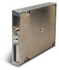
...kg) 2.83 lbs (1.27 kg) NOTE See Table 2-8 outlining weights for the GDL 69, GDL 69A, remote rack, and modular rack. Page 1-4 Revision E GDL 69/69A Installation Manual 190-00355-02 GDL 69/69A Specifications GDL 69/69A Characteristics Operating Temperature Range Input Voltage Range Software Compliance Environmental Compliance Specification -55°...VDC RTCA DO-178B Level D RTCA DO-160D Table 1-3. General Description 1.8 Technical Specifications The GDL 69/69A and GA 55/GA55A XM antenna are PMA approved and there is the responsibility of those desiring to install this equipment either on ...
...kg) 2.83 lbs (1.27 kg) NOTE See Table 2-8 outlining weights for the GDL 69, GDL 69A, remote rack, and modular rack. Page 1-4 Revision E GDL 69/69A Installation Manual 190-00355-02 GDL 69/69A Specifications GDL 69/69A Characteristics Operating Temperature Range Input Voltage Range Software Compliance Environmental Compliance Specification -55°...VDC RTCA DO-178B Level D RTCA DO-160D Table 1-3. General Description 1.8 Technical Specifications The GDL 69/69A and GA 55/GA55A XM antenna are PMA approved and there is the responsibility of those desiring to install this equipment either on ...

Installation Manual
Page 13
GDL 69/69A Modular Rack Unit Dimensions GDL 69/69A Installation Manual 190-00355-02 Page 1-5 Revision E GDL 69/69A Remote Rack Unit Dimensions 1.23 31.1 WITH DIMPLES 1.20 30.5 WITHOUT DIMPLES 6.90 175.3 TYP 7.26 184.4 6.30 160.0 3.00 76.2 ANTENNA J691 .60 15.2 .36 9.1 TYP .48 12.2 TYP 4.30 109.2 7.65 194...9.6 4X 3.73 94.7 Figure 1-3. General Description 8.26 [209.8] 7.9 [200.9] 6.91 [175.6] 3.57 [90.7] CENTER OF GRAVITY 1.48 [37.7] 6.43 [163.2] ANTENNA J691 0.73 [18.6] 0.37 [9.40] 3.98 [101.1] CENTER OF GRAVITY 8.74 [221.9] 1.60 [40.53] 4.46 [113.22] 0.49 [12.4] 0.73 [18....
GDL 69/69A Modular Rack Unit Dimensions GDL 69/69A Installation Manual 190-00355-02 Page 1-5 Revision E GDL 69/69A Remote Rack Unit Dimensions 1.23 31.1 WITH DIMPLES 1.20 30.5 WITHOUT DIMPLES 6.90 175.3 TYP 7.26 184.4 6.30 160.0 3.00 76.2 ANTENNA J691 .60 15.2 .36 9.1 TYP .48 12.2 TYP 4.30 109.2 7.65 194...9.6 4X 3.73 94.7 Figure 1-3. General Description 8.26 [209.8] 7.9 [200.9] 6.91 [175.6] 3.57 [90.7] CENTER OF GRAVITY 1.48 [37.7] 6.43 [163.2] ANTENNA J691 0.73 [18.6] 0.37 [9.40] 3.98 [101.1] CENTER OF GRAVITY 8.74 [221.9] 1.60 [40.53] 4.46 [113.22] 0.49 [12.4] 0.73 [18....
Installation Manual
Page 14
...This STC does not support installations of the GDL 69/69A. XM Antennas Model GA 55 GA 55A GA 57 Part Number 011-01033-00 011-01153-00 011-01032-00 Description XM Antenna XM Antenna GPS/WAAS + XM Antenna Mounting Configuration Stud mount Tear-drop form ...factor Thru-mount (ARINC 743 style mount) Thru-mount (ARINC 743 style mount) Table 1-6. General Description 1.8.1 General Antenna Requirements Garmin recommends the Garmin XM antenna shown in Table 1-6 should work with the GDL 69/69A...
...This STC does not support installations of the GDL 69/69A. XM Antennas Model GA 55 GA 55A GA 57 Part Number 011-01033-00 011-01153-00 011-01032-00 Description XM Antenna XM Antenna GPS/WAAS + XM Antenna Mounting Configuration Stud mount Tear-drop form ...factor Thru-mount (ARINC 743 style mount) Thru-mount (ARINC 743 style mount) Table 1-6. General Description 1.8.1 General Antenna Requirements Garmin recommends the Garmin XM antenna shown in Table 1-6 should work with the GDL 69/69A...

Installation Manual
Page 15
... Garmin Optional Displays GDU 1040 Installation Manual GA 55A, GA 56A and GA 57 Antenna Installation Manual XM™ Satellite Radio Activation Instructions MX20 Installation Manual SL15 Audio Panel Installation Manual SL10 Audio Panel Installation Manual 1.10 Certification The GDL 69 and GDL 69A ...XM Satellite Radios and the XM Satellite Radio Antenna have Parts Manufacturing Approval (PMA) for return shipments. Do not return the unit to abuse,...
... Garmin Optional Displays GDU 1040 Installation Manual GA 55A, GA 56A and GA 57 Antenna Installation Manual XM™ Satellite Radio Activation Instructions MX20 Installation Manual SL15 Audio Panel Installation Manual SL10 Audio Panel Installation Manual 1.10 Certification The GDL 69 and GDL 69A ...XM Satellite Radios and the XM Satellite Radio Antenna have Parts Manufacturing Approval (PMA) for return shipments. Do not return the unit to abuse,...
Installation Manual
Page 17
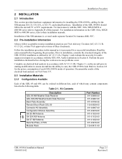
..., consider the structural integrity of the GDL 69/69A installation as it is covered under separate Garmin GA Antenna AML STC. 2.2 Pre-Installation Information Always follow the aircraft TC or STC requirements. For interconnects with the GDL 69A Audio Limitations in case problems occur. Kit Contents Description GDL 69 XM Weather Data Receiver GDL 69A XM Weather/Audio Data Receiver Back...
..., consider the structural integrity of the GDL 69/69A installation as it is covered under separate Garmin GA Antenna AML STC. 2.2 Pre-Installation Information Always follow the aircraft TC or STC requirements. For interconnects with the GDL 69A Audio Limitations in case problems occur. Kit Contents Description GDL 69 XM Weather Data Receiver GDL 69A XM Weather/Audio Data Receiver Back...
Installation Manual
Page 21
...could cause component damage. Table 2-2. After the cable assemblies are made through a 78-pin DSubminiature connector provided by Garmin. Route and secure the cable run from the GDL 69/69A to the rear of the rack. Required connectors and associated hardware are supplied with one of the recommended (or equivalent...near high-energy sources Refer to the rear plate using the screws provided in Appendix D. Use 22 or 24 AWG wire for the antenna connection, all electrical connections are made , attach the cable connector to the other units away from sources of electrical noise. Except ...
...could cause component damage. Table 2-2. After the cable assemblies are made through a 78-pin DSubminiature connector provided by Garmin. Route and secure the cable run from the GDL 69/69A to the rear of the rack. Required connectors and associated hardware are supplied with one of the recommended (or equivalent...near high-energy sources Refer to the rear plate using the screws provided in Appendix D. Use 22 or 24 AWG wire for the antenna connection, all electrical connections are made , attach the cable connector to the other units away from sources of electrical noise. Except ...

Installation Manual
Page 28
... and re-radiate the transmission causing a condition similar to having two COM antennas located in close proximity to ensure that their installation is not covered by Garmin. Page 2-12 Revision E GDL 69/69A Installation Manual 190-00355-02 NOTE Depending on the AML and follow limitations ...defined in the GDL 69/69A STC. It is a line-of 2332-2345 MHz for a satellite communications system. Locating antennas too close to be used...
... and re-radiate the transmission causing a condition similar to having two COM antennas located in close proximity to ensure that their installation is not covered by Garmin. Page 2-12 Revision E GDL 69/69A Installation Manual 190-00355-02 NOTE Depending on the AML and follow limitations ...defined in the GDL 69/69A STC. It is a line-of 2332-2345 MHz for a satellite communications system. Locating antennas too close to be used...

Installation Manual
Page 30
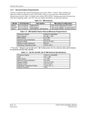
... in Table 1-6, and the installer must be added between the antenna and the XM receiver. The variable attenuation value required to attain the GDL 69/69A gain/loss component will be accounted for are shown in the GDL 69/69A has a system signal requirement of 20dB +/- 1dB gain from ... range of the XM receiver internal to the GDL 69/69A. The gain/loss factors that exist between the antenna and the GLD 69/69A RF input. Figure 2-9. XM Signal Gain Requirements Page 2-14 Revision E GDL 69/69A Installation Manual 190-00355-02 The GDL 69/69A has the capability to internally adjust for the...
... in Table 1-6, and the installer must be added between the antenna and the XM receiver. The variable attenuation value required to attain the GDL 69/69A gain/loss component will be accounted for are shown in the GDL 69/69A has a system signal requirement of 20dB +/- 1dB gain from ... range of the XM receiver internal to the GDL 69/69A. The gain/loss factors that exist between the antenna and the GLD 69/69A RF input. Figure 2-9. XM Signal Gain Requirements Page 2-14 Revision E GDL 69/69A Installation Manual 190-00355-02 The GDL 69/69A has the capability to internally adjust for the...

Installation Manual
Page 31
... programmed into the configuration module during post installation checkout. If the GDL 69/69A gain/loss component is different from the default cable, use this STC. GDL 69/69A Gain/Loss (4) +6dB > x > -4dB Total Gain Antenna/Receiver +/= 20 dB Note: (1) Garmin GA 55, GA 55A, GA 57 XM antenna typical gain 25 dB. The factory default setting for explanation...
... programmed into the configuration module during post installation checkout. If the GDL 69/69A gain/loss component is different from the default cable, use this STC. GDL 69/69A Gain/Loss (4) +6dB > x > -4dB Total Gain Antenna/Receiver +/= 20 dB Note: (1) Garmin GA 55, GA 55A, GA 57 XM antenna typical gain 25 dB. The factory default setting for explanation...

Installation Manual
Page 32
... to installation. 3. To reduce the need to configure the GDL 69/69A for cable loss, the GDL 69/69A is : GLcomp = 20dB - 25dB + 3.61dB = -5dB + 3.61dB = - 1.39dB The GDL 69/69A gain/loss component will be configured for the amount of antenna cable loss. With the GDL 69/69A receiver and antenna installed, route and clamp the coaxial cable in accordance with a cable loss...
... to installation. 3. To reduce the need to configure the GDL 69/69A for cable loss, the GDL 69/69A is : GLcomp = 20dB - 25dB + 3.61dB = -5dB + 3.61dB = - 1.39dB The GDL 69/69A gain/loss component will be configured for the amount of antenna cable loss. With the GDL 69/69A receiver and antenna installed, route and clamp the coaxial cable in accordance with a cable loss...

Installation Manual
Page 33
...remote power control signal. NOTE Circuits should be protected in AC 43.13-1B, Chapter 10, Section 2. Use the following values for computation: GDL 69 Unit Status Off On GDL 69A Max Current @ 28 VDC 0.01 A 0.28 A Max Current @ 14 VDC 0.01 A 0.425 A Unit Status Off On Max Current... the installation of gravity. Unit Weights Item GDL 69 Weight GDL 69 and Remote Rack Weight GDL 69 and Modular Rack Weight GDL 69A Weight GDL 69A and Remote Rack Weight GDL 69A and Modular Rack Weight GA 55 Antenna GA 55A Antenna GA 57 Antenna Weight 1.72 lbs (0.78 kg) 2.69 lbs (1.22 kg) 2.67 lbs (1.21...
...remote power control signal. NOTE Circuits should be protected in AC 43.13-1B, Chapter 10, Section 2. Use the following values for computation: GDL 69 Unit Status Off On GDL 69A Max Current @ 28 VDC 0.01 A 0.28 A Max Current @ 14 VDC 0.01 A 0.425 A Unit Status Off On Max Current... the installation of gravity. Unit Weights Item GDL 69 Weight GDL 69 and Remote Rack Weight GDL 69 and Modular Rack Weight GDL 69A Weight GDL 69A and Remote Rack Weight GDL 69A and Modular Rack Weight GA 55 Antenna GA 55A Antenna GA 57 Antenna Weight 1.72 lbs (0.78 kg) 2.69 lbs (1.22 kg) 2.67 lbs (1.21...

Installation Manual
Page 39
...Ground NOTE In order for interconnect information. The configuration module does not store XM Satellite Radio subscription information. When a new GDL 69/69A is obtained from GDL 69/69A) Refer to Appendix D for a serial port to function correctly, the baud rate of the RX and TX channels on ... pins contain no lightning protection, the configuration module must be provided by two different power busses. The antenna cable connection is not used to connect the GDL 69/69A to control/display devices (e.g., the MX20). Typically, both power input pins are provided on the sub-miniature...
...Ground NOTE In order for interconnect information. The configuration module does not store XM Satellite Radio subscription information. When a new GDL 69/69A is obtained from GDL 69/69A) Refer to Appendix D for a serial port to function correctly, the baud rate of the RX and TX channels on ... pins contain no lightning protection, the configuration module must be provided by two different power busses. The antenna cable connection is not used to connect the GDL 69/69A to control/display devices (e.g., the MX20). Typically, both power input pins are provided on the sub-miniature...

Installation Manual
Page 45
.... 4.4.1 Data Link Status and Connection Power up the GDL 69/69A. View the SUMMARY field and ensure that the GDL 69/69A is properly programmed and the GDL 69/69A connected to access the data link status page on the MX20 GDL 69/69A Installation Manual 190-00355-02 Page 4-3 Revision E System... Configuration/Checkout 10. Set this setting to verify XM signals are 'complete', then de-activate the cursor. 11. Figure 4-1. View the data link status on how to the correct communication port. The antenna...
.... 4.4.1 Data Link Status and Connection Power up the GDL 69/69A. View the SUMMARY field and ensure that the GDL 69/69A is properly programmed and the GDL 69/69A connected to access the data link status page on the MX20 GDL 69/69A Installation Manual 190-00355-02 Page 4-3 Revision E System... Configuration/Checkout 10. Set this setting to verify XM signals are 'complete', then de-activate the cursor. 11. Figure 4-1. View the data link status on how to the correct communication port. The antenna...
Installation Manual
Page 49
...). • Verify wiring of satellite constellation. • Check the antenna cable and connectors. • Verify correct antenna loss value in the configuration module. • Verify antenna ground plane is GDL 69A, and not GDL 69 (with no XM subscribed services displayed • Verify subscription with GDL 69/69A. activated. (GDL 69A only) GDL 69/69A Installation Manual 190-00355-02 Page 5-1 Revision E No audio output...
...). • Verify wiring of satellite constellation. • Check the antenna cable and connectors. • Verify correct antenna loss value in the configuration module. • Verify antenna ground plane is GDL 69A, and not GDL 69 (with no XM subscribed services displayed • Verify subscription with GDL 69/69A. activated. (GDL 69A only) GDL 69/69A Installation Manual 190-00355-02 Page 5-1 Revision E No audio output...

Installation Manual
Page 51
... the scope of the GDL 69/69A STC. All equipment interfaced to the GDL 69/69A must disable XM audio to crew locations by means of essential equipment in this STC does not provide data for all aircraft on the GDL 69A. 6.2 Installation The GDL 69A XM Satellite Radio audio ...entertainment may determine that each installation or aircraft type must be previously or concurrently approved. 6.2.3 Preservation of Previous Systems It is compatible with the Garmin antennas listed in Table 1-5 or ...
... the scope of the GDL 69/69A STC. All equipment interfaced to the GDL 69/69A must disable XM audio to crew locations by means of essential equipment in this STC does not provide data for all aircraft on the GDL 69A. 6.2 Installation The GDL 69A XM Satellite Radio audio ...entertainment may determine that each installation or aircraft type must be previously or concurrently approved. 6.2.3 Preservation of Previous Systems It is compatible with the Garmin antennas listed in Table 1-5 or ...

Installation Manual
Page 63
Antenna Mounting Diagrams Figure D-1. GDL 69 Interconnect to MFD and Audio Panel GDL 69/69A Installation Manual 190-00355-02 Page D-3 Revision E
Antenna Mounting Diagrams Figure D-1. GDL 69 Interconnect to MFD and Audio Panel GDL 69/69A Installation Manual 190-00355-02 Page D-3 Revision E

