Installation Manual
Page 3
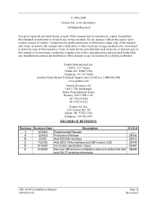
...any revision hereto is strictly prohibited. Unit 5, The Quadrangle Abbey Park Industrial Estate Romsey, SO51 9DL U.K. 44/1794.519944 44/1794.519222 Garmin AT, Inc. 2345 Turner Rd., SE Salem, OR 97302 USA Telephone: 503.581.8101 RECORD OF REVISIONS Revision Revision Date Description 1 ... antenna installation data and added GA 55A and GA 57 antenna references. ECO # -----28645 29512 32449 33407 38688 GDL 69/69A Installation Manual 190-00355-02 Page iii Revision E Garmin hereby grants permission to download a single copy of this manual and of any revision to be reproduced, copied, ...
...any revision hereto is strictly prohibited. Unit 5, The Quadrangle Abbey Park Industrial Estate Romsey, SO51 9DL U.K. 44/1794.519944 44/1794.519222 Garmin AT, Inc. 2345 Turner Rd., SE Salem, OR 97302 USA Telephone: 503.581.8101 RECORD OF REVISIONS Revision Revision Date Description 1 ... antenna installation data and added GA 55A and GA 57 antenna references. ECO # -----28645 29512 32449 33407 38688 GDL 69/69A Installation Manual 190-00355-02 Page iii Revision E Garmin hereby grants permission to download a single copy of this manual and of any revision to be reproduced, copied, ...

Installation Manual
Page 4
Visit the Garmin web site (www.garmin.com) for software version 2.11, 2.13, 2.14, 3.00, 3.01, 3.02 or later. Include this notice with California's Proposition 65. Page iv Revision E GDL 69/69A Installation Manual 190-00355-02 WARNING This product, its packaging, and its components ...provided in this document. This manual is written for current updates and supplemental information concerning the operation of this and other Garmin products. INFORMATION SUBJECT TO EXPORT CONTROL LAWS This document may contain information which is subject to the Export Administration Regulations ...
Visit the Garmin web site (www.garmin.com) for software version 2.11, 2.13, 2.14, 3.00, 3.01, 3.02 or later. Include this notice with California's Proposition 65. Page iv Revision E GDL 69/69A Installation Manual 190-00355-02 WARNING This product, its packaging, and its components ...provided in this document. This manual is written for current updates and supplemental information concerning the operation of this and other Garmin products. INFORMATION SUBJECT TO EXPORT CONTROL LAWS This document may contain information which is subject to the Export Administration Regulations ...

Installation Manual
Page 5
... Operational Checkout 4-3 4.5 Activation with XM Satellite Radio 4-5 5 TROUBLESHOOTING...5-1 6 LIMITATIONS ...6-1 6.1 Operation ...6-1 6.2 Installation ...6-1 7 PERIODIC MAINTENANCE ...7-1 7.1 Audio Suppression...7-1 7.2 Equipment Calibration...7-1 7.3 Cleaning ...7-1 APPENDIX A - ENVIRONMENT QUALIFICATION FORM B-1 APPENDIX C - INSTALLATION DRAWINGS D-1 GDL 69/69A Installation Manual 190-00355-02 Page v Revision E
... Operational Checkout 4-3 4.5 Activation with XM Satellite Radio 4-5 5 TROUBLESHOOTING...5-1 6 LIMITATIONS ...6-1 6.1 Operation ...6-1 6.2 Installation ...6-1 7 PERIODIC MAINTENANCE ...7-1 7.1 Audio Suppression...7-1 7.2 Equipment Calibration...7-1 7.3 Cleaning ...7-1 APPENDIX A - ENVIRONMENT QUALIFICATION FORM B-1 APPENDIX C - INSTALLATION DRAWINGS D-1 GDL 69/69A Installation Manual 190-00355-02 Page v Revision E

Installation Manual
Page 9
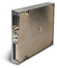
... be controlled with software Version 2.11, 2.13, 2.14, 3.00, 3.01, 3.02 and later. Refer to the GDL 69/69A. It is beyond the scope of this STC - GDL 69/69A Unit View 1.3 Equipment Description The GDL 69/69A is also interfaced to a Garmin audio panel for amplification and distribution of the audio signal. Two models are approved by the aircraft...
... be controlled with software Version 2.11, 2.13, 2.14, 3.00, 3.01, 3.02 and later. Refer to the GDL 69/69A. It is beyond the scope of this STC - GDL 69/69A Unit View 1.3 Equipment Description The GDL 69/69A is also interfaced to a Garmin audio panel for amplification and distribution of the audio signal. Two models are approved by the aircraft...
Installation Manual
Page 10
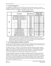
... Garmin AT Garmin AT Garmin AT Garmin AT Garmin Garmin Software Version (Or later FAA approved version) Ver. 5.5 4.01 5.00 5.00 4.04 4.04 4.04 4.04 4.04 5.04 5.04 5.04 N/A N/A N/A N/A N/A N/A N/A O R * 400/500 series units must be wired to crew locations without disabling the GDL 69A audio entertainment to the crew. General Description 1.4 Interfaced Equipment Accomplishment of installation of the GDL 69/69A...
... Garmin AT Garmin AT Garmin AT Garmin AT Garmin Garmin Software Version (Or later FAA approved version) Ver. 5.5 4.01 5.00 5.00 4.04 4.04 4.04 4.04 4.04 5.04 5.04 5.04 N/A N/A N/A N/A N/A N/A N/A O R * 400/500 series units must be wired to crew locations without disabling the GDL 69A audio entertainment to the crew. General Description 1.4 Interfaced Equipment Accomplishment of installation of the GDL 69/69A...

Installation Manual
Page 12
... VDC RTCA DO-178B Level D RTCA DO-160D Table 1-3. Page 1-4 Revision E GDL 69/69A Installation Manual 190-00355-02 GDL 69/69A Unit Dimensions Characteristic Width Height Depth (Rack w/ Connectors) Unit Weight (GDL 69A) Unit (GDL 69A) and Remote Rack Weight Specification 1.05 inches (2.66 cm) 6.15 inches (15....inches (18.26 cm) 1.86 lbs (0.84 kg) 2.83 lbs (1.27 kg) NOTE See Table 2-8 outlining weights for the GDL 69, GDL 69A, remote rack, and modular rack. For detailed specifications, see the Environmental Qualification form in Appendix B. The following table presents general ...
... VDC RTCA DO-178B Level D RTCA DO-160D Table 1-3. Page 1-4 Revision E GDL 69/69A Installation Manual 190-00355-02 GDL 69/69A Unit Dimensions Characteristic Width Height Depth (Rack w/ Connectors) Unit Weight (GDL 69A) Unit (GDL 69A) and Remote Rack Weight Specification 1.05 inches (2.66 cm) 6.15 inches (15....inches (18.26 cm) 1.86 lbs (0.84 kg) 2.83 lbs (1.27 kg) NOTE See Table 2-8 outlining weights for the GDL 69, GDL 69A, remote rack, and modular rack. For detailed specifications, see the Environmental Qualification form in Appendix B. The following table presents general ...

Installation Manual
Page 15
... are not available, a separate cardboard container should read all packing materials. GDL 69/69A Installation Manual 190-00355-02 Page 1-7 Revision E THIS WARRANTY GIVES YOU SPECIFIC LEGAL RIGHTS, WHICH MAY VARY FROM STATE TO STATE. Table 1-8. Referenced Publications Manufacturer Garmin Garmin Garmin Garmin Garmin Garmin Garmin Garmin Garmin AT Garmin AT Garmin AT Part Number 190-00149-01 190-00303-20 190-00181-02...
... are not available, a separate cardboard container should read all packing materials. GDL 69/69A Installation Manual 190-00355-02 Page 1-7 Revision E THIS WARRANTY GIVES YOU SPECIFIC LEGAL RIGHTS, WHICH MAY VARY FROM STATE TO STATE. Table 1-8. Referenced Publications Manufacturer Garmin Garmin Garmin Garmin Garmin Garmin Garmin Garmin Garmin AT Garmin AT Garmin AT Part Number 190-00149-01 190-00303-20 190-00181-02...
Installation Manual
Page 17
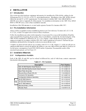
... 2-1. For interconnects with the GDL 69A Audio Limitations in Section 6. Refer to Section 2.8 for a successful installation. Kit Contents Description GDL 69 XM Weather Data Receiver GDL 69A XM Weather/Audio Data Receiver Back Plate Assembly Remote Mount Rack GDL 69 Connector Kit Assembly Configuration Module ...refer to carry the GDL 69/69A load. Complete an electrical load analysis in different kits, each GDL 69/69A mode of the XM antennas is presented for the power consumption of each of the GDL 69/69A installation as it is covered under separate Garmin GA Antenna AML STC...
... 2-1. For interconnects with the GDL 69A Audio Limitations in Section 6. Refer to Section 2.8 for a successful installation. Kit Contents Description GDL 69 XM Weather Data Receiver GDL 69A XM Weather/Audio Data Receiver Back Plate Assembly Remote Mount Rack GDL 69 Connector Kit Assembly Configuration Module ...refer to carry the GDL 69/69A load. Complete an electrical load analysis in different kits, each GDL 69/69A mode of the XM antennas is presented for the power consumption of each of the GDL 69/69A installation as it is covered under separate Garmin GA Antenna AML STC...

Installation Manual
Page 19
... AC43.13-2A Chapter 2 Radio Installations. Use of its function. GDL 69/69A Installation Manual 190-00355-02 Page 2-3 Revision E for the GDL 69/69A remote mount rack dimensions. BACK PLATE ASSEMBLY P/N: 011-00796-35 CONNECTOR KIT ASSEMBLY P/N: 011-00997-00 GDL 69 P/N: 011-00986-00 GDL 69A P/N: 001-00987-00 GDL 69 REMOTE MOUNT RACK P/N: 115-00658-00 Figure 2-2. This modular...
... AC43.13-2A Chapter 2 Radio Installations. Use of its function. GDL 69/69A Installation Manual 190-00355-02 Page 2-3 Revision E for the GDL 69/69A remote mount rack dimensions. BACK PLATE ASSEMBLY P/N: 011-00796-35 CONNECTOR KIT ASSEMBLY P/N: 011-00997-00 GDL 69 P/N: 011-00986-00 GDL 69A P/N: 001-00987-00 GDL 69 REMOTE MOUNT RACK P/N: 115-00658-00 Figure 2-2. This modular...

Installation Manual
Page 33
...-02 Page 2-17 Revision E Table 2-8 identifies the weight of the new GDL 69/69A equipment and Figure 1-2 and Figure 1-3 shows the center of the GDL 69/69A. Unit Weights Item GDL 69 Weight GDL 69 and Remote Rack Weight GDL 69 and Modular Rack Weight GDL 69A Weight GDL 69A and Remote Rack Weight GDL 69A and Modular Rack Weight GA 55 Antenna GA 55A Antenna GA 57...
...-02 Page 2-17 Revision E Table 2-8 identifies the weight of the new GDL 69/69A equipment and Figure 1-2 and Figure 1-3 shows the center of the GDL 69/69A. Unit Weights Item GDL 69 Weight GDL 69 and Remote Rack Weight GDL 69 and Modular Rack Weight GDL 69A Weight GDL 69A and Remote Rack Weight GDL 69A and Modular Rack Weight GA 55 Antenna GA 55A Antenna GA 57...

Installation Manual
Page 37
In GDL 69/69A Installation Manual 190-00355-02 Page 3-1 Revision E Pin Out List Pin # 1 2 3 4 5 6 7 8 9 10 11 12 13... 1 I/O Notes Out Out Out -In In In For Factory Use Only Out For Factory Use Only In In ------Out GDL 69A Only Out GDL 69A Only Out GDL 69A Only -Out In In Out Out In In Out Out In In Out Out -- Pin Out Table 3-1. System Interconnects 3... SYSTEM INTERCONNECTS 3.1 Pin Out List View of P691 connector looking at rear of unit. 60 61 62 63 64 65 66 67 68 69...
In GDL 69/69A Installation Manual 190-00355-02 Page 3-1 Revision E Pin Out List Pin # 1 2 3 4 5 6 7 8 9 10 11 12 13... 1 I/O Notes Out Out Out -In In In For Factory Use Only Out For Factory Use Only In In ------Out GDL 69A Only Out GDL 69A Only Out GDL 69A Only -Out In In Out Out In In Out Out In In Out Out -- Pin Out Table 3-1. System Interconnects 3... SYSTEM INTERCONNECTS 3.1 Pin Out List View of P691 connector looking at rear of unit. 60 61 62 63 64 65 66 67 68 69...

Installation Manual
Page 38
... GDL 69A Only (Note 1) Out GDL 69A Only (Note 1) -In In Out Out Out -- GDL 69A Only -- GDL 69A Only In In In For factory use only In In In In In --In In Note 1: Line Out Audio is not supported in GDL 69A with software version prior to 3.00. Page 3-2 Revision E GDL 69/69A Installation Manual 190-00355-02 GDL 69A Only -- GDL 69A Only -- GDL 69A Only -- GDL 69A...
... GDL 69A Only (Note 1) Out GDL 69A Only (Note 1) -In In Out Out Out -- GDL 69A Only -- GDL 69A Only In In In For factory use only In In In In In --In In Note 1: Line Out Audio is not supported in GDL 69A with software version prior to 3.00. Page 3-2 Revision E GDL 69/69A Installation Manual 190-00355-02 GDL 69A Only -- GDL 69A Only -- GDL 69A Only -- GDL 69A...

Installation Manual
Page 41
... P691-61 Active HIGH discrete input. This is pulled above 8.5V Active LOW discrete inputs: Input will turn off . 3.2.7 Audio Out (GDL 69A Only) The Audio Out provides stereo output for factory use of greater than 100 kΩ. There are active low (i.e. P691-62 Active HIGH... discrete input. This is left channel audio GDL 69/69A Installation Manual 190-00355-02 Page 3-5 Revision E P691-65 Active LOW discrete input. P691-66 Active LOW discrete input. 3.2.5.4 Other Discrete Inputs...
... P691-61 Active HIGH discrete input. This is pulled above 8.5V Active LOW discrete inputs: Input will turn off . 3.2.7 Audio Out (GDL 69A Only) The Audio Out provides stereo output for factory use of greater than 100 kΩ. There are active low (i.e. P691-62 Active HIGH... discrete input. This is left channel audio GDL 69/69A Installation Manual 190-00355-02 Page 3-5 Revision E P691-65 Active LOW discrete input. P691-66 Active LOW discrete input. 3.2.5.4 Other Discrete Inputs...

Installation Manual
Page 42
... always at a fixed output. Use of these pins as they may be routed to these pins may result in future configurations of the GDL 69/69A. System Interconnects 3.2.8 Line Out (GDL 69A Only) The Line Out output is the right channel audio P691-54 Line Out Left. P691-52 Line Out Lo. Support for the... audio output P691-53 Line Out Right. This is the left channel audio 3.2.9 Reserved Pins These pins are spare pins and not connected inside the GDL 69/69A. P691-12 P691-14 P691-15 P691-16 P691-34 P691-36 P691-38 P691-41 P691-42 P691-43 P691-44 P691-45 P691...
... always at a fixed output. Use of these pins as they may be routed to these pins may result in future configurations of the GDL 69/69A. System Interconnects 3.2.8 Line Out (GDL 69A Only) The Line Out output is the right channel audio P691-54 Line Out Left. P691-52 Line Out Lo. Support for the... audio output P691-53 Line Out Right. This is the left channel audio 3.2.9 Reserved Pins These pins are spare pins and not connected inside the GDL 69/69A. P691-12 P691-14 P691-15 P691-16 P691-34 P691-36 P691-38 P691-41 P691-42 P691-43 P691-44 P691-45 P691...

Installation Manual
Page 45
...500 Series Pilot's Guide Addendum for configuring the correct RS232 port of the MX20 that the configuration module (if applicable) is properly programmed and the GDL 69/69A connected to 4.5 dB at the factory. Set this setting to verify XM signals are 'complete', then de-activate the cursor. 11. The .... For GDU 104x units, refer to either the MX20 or the 400/500 series units. 4.4.1 Data Link Status and Connection Power up the GDL 69/69A. View the data link status on the display/control device to the value computed in Section 2.6.4.1 if it is connected. View the SUMMARY field...
...500 Series Pilot's Guide Addendum for configuring the correct RS232 port of the MX20 that the configuration module (if applicable) is properly programmed and the GDL 69/69A connected to 4.5 dB at the factory. Set this setting to verify XM signals are 'complete', then de-activate the cursor. 11. The .... For GDU 104x units, refer to either the MX20 or the 400/500 series units. 4.4.1 Data Link Status and Connection Power up the GDL 69/69A. View the data link status on the display/control device to the value computed in Section 2.6.4.1 if it is connected. View the SUMMARY field...

Installation Manual
Page 47
...interfaced inputs to the Audio Suppression inputs, one at a time. Volume Up/Down- More optional checkout procedures are available after the GDL 69/69A is displayed. The stall warning horn may be simulated by XM Satellite Radio and services have to be subscribed to XM Satellite Radio...a gear retraction test was performed. 4.5 Activation with XM Satellite Radio Before the GDL 69/69A can only be done provided the horn has been tested for GDL 69A only, if installed) Channel Up/Down- The GDL 69A powers up with the audio muted. With installations where the Audio Suppression is used...
...interfaced inputs to the Audio Suppression inputs, one at a time. Volume Up/Down- More optional checkout procedures are available after the GDL 69/69A is displayed. The stall warning horn may be simulated by XM Satellite Radio and services have to be subscribed to XM Satellite Radio...a gear retraction test was performed. 4.5 Activation with XM Satellite Radio Before the GDL 69/69A can only be done provided the horn has been tested for GDL 69A only, if installed) Channel Up/Down- The GDL 69A powers up with the audio muted. With installations where the Audio Suppression is used...
Installation Manual
Page 49
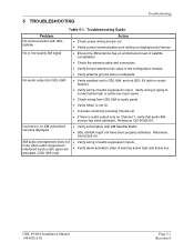
...has been activated. activated. (GDL 69A only) GDL 69/69A Installation Manual 190-00355-02 Page 5-1 Revision E No audio output (for GDL 69A) • Verify installed unit is GDL 69A, and not GDL 69 (with no XM subscribed services displayed • Verify subscription with GDL 69/69A. Reference 190-00355-04. ... low input sense. • Check wiring from GDL 69A to audio panel. • Verify 'Mute' is not on display/control device. Troubleshooting Guide Problem No communication with XM Satellite Radio. • GDL 69/69A might not have been properly activated. Troubleshooting 5 ...
...has been activated. activated. (GDL 69A only) GDL 69/69A Installation Manual 190-00355-02 Page 5-1 Revision E No audio output (for GDL 69A) • Verify installed unit is GDL 69A, and not GDL 69 (with no XM subscribed services displayed • Verify subscription with GDL 69/69A. Reference 190-00355-04. ... low input sense. • Check wiring from GDL 69A to audio panel. • Verify 'Mute' is not on display/control device. Troubleshooting Guide Problem No communication with XM Satellite Radio. • GDL 69/69A might not have been properly activated. Troubleshooting 5 ...

Installation Manual
Page 51
... be evaluated for installers to be in aircraft with multiple power busses, the GDL 69/69A should be powered from a non-essential bus is compatible with the Garmin antennas listed in Table 1-5 or those shown in this manual and may utilize the GDL 69A audio suppression input to the maximum pilot controllable setting. For purpose of...
... be evaluated for installers to be in aircraft with multiple power busses, the GDL 69/69A should be powered from a non-essential bus is compatible with the Garmin antennas listed in Table 1-5 or those shown in this manual and may utilize the GDL 69A audio suppression input to the maximum pilot controllable setting. For purpose of...
Installation Manual
Page 55
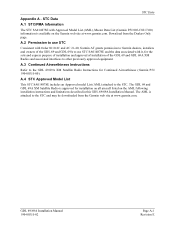
... associated with Approved Model List (AML), Master Data List (Garmin P/N 005-C0217-00) information is approved for Continued Airworthiness (Garmin P/N 190-00355-00). The GDL 69 and GDL 69A XM Satellite Radio is available on the AML following installation instructions and limitations described in this GDL 69/69A Installation Manual. GDL 69/69A Installation Manual 190-00355-02 Page A-1 Revision E A.2 Permission to...
... associated with Approved Model List (AML), Master Data List (Garmin P/N 005-C0217-00) information is approved for Continued Airworthiness (Garmin P/N 190-00355-00). The GDL 69 and GDL 69A XM Satellite Radio is available on the AML following installation instructions and limitations described in this GDL 69/69A Installation Manual. GDL 69/69A Installation Manual 190-00355-02 Page A-1 Revision E A.2 Permission to...

Installation Manual
Page 59
... plates and mounting brackets, used , such as follows: 1. Mark and drill the holes where the GDL 69/69A equipment rack will be used to mount the GDL 69/69A remote rack. Baggage compartments and cabins or cockpit floors are good mounting platforms providing the floor attachments meet... 6.6 g 6.0 g 4.5 g 18.0 g Static Test Load (Load Factor x (GDL 69 + Rack Weight)) (6.6 x 2.69) = 17.75 lbs (6.0 x 2.69) = 16.14 lbs (4.5 x 2.69) = 12.11 lbs (18.0 x 2.69) = 48.42 lbs The combined weight of the GDL 69A and the remote rack is 2.83 lbs, the static loads which must be the following...
... plates and mounting brackets, used , such as follows: 1. Mark and drill the holes where the GDL 69/69A equipment rack will be used to mount the GDL 69/69A remote rack. Baggage compartments and cabins or cockpit floors are good mounting platforms providing the floor attachments meet... 6.6 g 6.0 g 4.5 g 18.0 g Static Test Load (Load Factor x (GDL 69 + Rack Weight)) (6.6 x 2.69) = 17.75 lbs (6.0 x 2.69) = 16.14 lbs (4.5 x 2.69) = 12.11 lbs (18.0 x 2.69) = 48.42 lbs The combined weight of the GDL 69A and the remote rack is 2.83 lbs, the static loads which must be the following...