
Installation Manual
Page 19
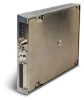
...00 GDL 69 P/N: 011-00986-00 GDL 69A P/N: 001-00987-00 GDL 69 REMOTE MOUNT RACK P/N: 115-00658-00 Figure 2-2. GDL 69/69A Remote Mount Rack 2.4.3 G1000 Modular Rack The G1000 modular rack is of sufficient structural integrity, refer to Figure 1-2 for discrete switches should be 24 AWG (MIL Spec M22759)... and should be installed in a variety of rocker switches should be mounted to a surface known to have sufficient structural integrity to install the GDL 69/69A in contact with AC43.13-2A Chapter 2 Radio ...
...00 GDL 69 P/N: 011-00986-00 GDL 69A P/N: 001-00987-00 GDL 69 REMOTE MOUNT RACK P/N: 115-00658-00 Figure 2-2. GDL 69/69A Remote Mount Rack 2.4.3 G1000 Modular Rack The G1000 modular rack is of sufficient structural integrity, refer to Figure 1-2 for discrete switches should be 24 AWG (MIL Spec M22759)... and should be installed in a variety of rocker switches should be mounted to a surface known to have sufficient structural integrity to install the GDL 69/69A in contact with AC43.13-2A Chapter 2 Radio ...
Installation Manual
Page 25
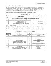
... the backshell. Most parts for the drawings shown in Table 2-5. Included Garmin Part Number/MIL Spec 0 011-00950-( ) 011-00980-00 1 or 011-00980-01 0 Parts used depend on method chosen 0 Reference Interconnect Diagrams 0 336-00021-00 0 MS25036-152 0 011-00950-( ) 0 211-60234-10 GDL 69/69A Installation Manual 190-00355-02 Page 2-9 Revision E Included...
... the backshell. Most parts for the drawings shown in Table 2-5. Included Garmin Part Number/MIL Spec 0 011-00950-( ) 011-00980-00 1 or 011-00980-01 0 Parts used depend on method chosen 0 Reference Interconnect Diagrams 0 336-00021-00 0 MS25036-152 0 011-00950-( ) 0 211-60234-10 GDL 69/69A Installation Manual 190-00355-02 Page 2-9 Revision E Included...
Installation Manual
Page 26
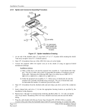
... number of the AWG #24 wires (4) on the Spider. 3. b) Solder the prepared wire assembly (4, 7). Reference the following MIL-Specs for the remaining shielded cables (7). Use only one of conductors present in the cable. Spider Installation Drawing 1. Strip 1/8" of insulation from...wire assembly (4, 7) and shrink with Silicone Fusion Tape (Garmin P/N: 249-00114-00 or a similar version) at the point where the backshell strain relief (10) and cast housing (1) contacts the cable Page 2-10 Revision E GDL 69/69A Installation Manual 190-00355-02 Slide a piece of shrink tube...
... number of the AWG #24 wires (4) on the Spider. 3. b) Solder the prepared wire assembly (4, 7). Reference the following MIL-Specs for the remaining shielded cables (7). Use only one of conductors present in the cable. Spider Installation Drawing 1. Strip 1/8" of insulation from...wire assembly (4, 7) and shrink with Silicone Fusion Tape (Garmin P/N: 249-00114-00 or a similar version) at the point where the backshell strain relief (10) and cast housing (1) contacts the cable Page 2-10 Revision E GDL 69/69A Installation Manual 190-00355-02 Slide a piece of shrink tube...