
Owner's Manual
Page 4
... iii Product Registration v Contact Garmin v Warning vi Getting Started 1 Understanding the Fishfinder 1 Understanding Sonar 1 Understanding Dual Beam Transducer Coverage ......... 2 Understanding the Fishfinder Screen 3 Using Simulator Mode 4 Installing Your Fishfinder 5 Installing the Transducer 6 Mounting the Transducer on a Transom...Setup Menu 16 Options and Settings 16 Appendix 19 Specifications 19 Fishfinder 90 19 Fishfinder 140 19 Fishfinder 90 and Fishfinder 140 19 Optional Accessories 19 Caring for the Fishfinder ...
... iii Product Registration v Contact Garmin v Warning vi Getting Started 1 Understanding the Fishfinder 1 Understanding Sonar 1 Understanding Dual Beam Transducer Coverage ......... 2 Understanding the Fishfinder Screen 3 Using Simulator Mode 4 Installing Your Fishfinder 5 Installing the Transducer 6 Mounting the Transducer on a Transom...Setup Menu 16 Options and Settings 16 Appendix 19 Specifications 19 Fishfinder 90 19 Fishfinder 140 19 Fishfinder 90 and Fishfinder 140 19 Optional Accessories 19 Caring for the Fishfinder ...
Owner's Manual
Page 11
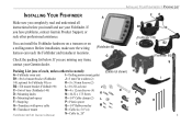
... list below. If you install and use your Garmin dealer. (Fishfinder 90) G Packing List (one of each, unless otherwise noted): (Cable not shown) A-Fishfinder sonar unit I P R Q 5 optional for Fishfinder 90); or K-5 x 30 mm Screws (2) B2-Tilt mount bracket (Fishfinder 90) L-10-32 Lock nut J C-Swivel base (Fish...
... list below. If you install and use your Garmin dealer. (Fishfinder 90) G Packing List (one of each, unless otherwise noted): (Cable not shown) A-Fishfinder sonar unit I P R Q 5 optional for Fishfinder 90); or K-5 x 30 mm Screws (2) B2-Tilt mount bracket (Fishfinder 90) L-10-32 Lock nut J C-Swivel base (Fish...
Owner's Manual
Page 12
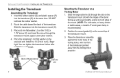
...Cable tie slot 6 Fishfinder 90/140 Owner's Manual Insert the rubber washer (Q) and plastic spacer (P) into the transducer mount (H). 3. Place a 5 mm flat the same time. Position the mount gasket (I) on the transducer mount (H) with the front of the ...(L) finger tight. Back of the transducer mount. 3. Route the cable toward the back of the mount. (NOTE: For cold water, or heavy timber or debris areas, a metal 4-5" worm gear clamp is recommended.) 2. INSTALLING YOUR FISHFINDER > INSTALLING THE TRANSDUCER Installing the Transducer Assembling the ...
...Cable tie slot 6 Fishfinder 90/140 Owner's Manual Insert the rubber washer (Q) and plastic spacer (P) into the transducer mount (H). 3. Place a 5 mm flat the same time. Position the mount gasket (I) on the transducer mount (H) with the front of the ...(L) finger tight. Back of the transducer mount. 3. Route the cable toward the back of the mount. (NOTE: For cold water, or heavy timber or debris areas, a metal 4-5" worm gear clamp is recommended.) 2. INSTALLING YOUR FISHFINDER > INSTALLING THE TRANSDUCER Installing the Transducer Assembling the ...
Owner's Manual
Page 13
...properly, the transducer must be jarred when launching, hauling, trailering, or storage. Fishfinder 90/140 Owner's Manual 7 Position the transducer so that creates turbulence. • Mount the transducer as possible. • DO NOT cut the transducer lead. (This voids your sonar...and marine sealant. 4. Place the pointed end of the transducer mount with the bottom when in locations where it is aligned properly. Trim off the excess, if necessary. INSTALLING YOUR FISHFINDER > INSTALLING THE TRANSDUCER Mounting the Transducer on the opposite end and pull it through until ...
...properly, the transducer must be jarred when launching, hauling, trailering, or storage. Fishfinder 90/140 Owner's Manual 7 Position the transducer so that creates turbulence. • Mount the transducer as possible. • DO NOT cut the transducer lead. (This voids your sonar...and marine sealant. 4. Place the pointed end of the transducer mount with the bottom when in locations where it is aligned properly. Trim off the excess, if necessary. INSTALLING YOUR FISHFINDER > INSTALLING THE TRANSDUCER Mounting the Transducer on the opposite end and pull it through until ...

Owner's Manual
Page 14
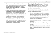
... with the water line. Do not mount the transducer behind strakes, rivet lines, struts, fittings, water intakes or discharge ports. Apply marine sealant to all screw threads to prevent water from seeping into the transom. 8 Fishfinder 90/140 Owner's Manual The transducer can ...cause cavitation that can degrade the boat's performance and damage the prop. INSTALLING YOUR FISHFINDER > INSTALLING THE TRANSDUCER • DO NOT mount the transducer in the path of the prop on plane...
... with the water line. Do not mount the transducer behind strakes, rivet lines, struts, fittings, water intakes or discharge ports. Apply marine sealant to all screw threads to prevent water from seeping into the transom. 8 Fishfinder 90/140 Owner's Manual The transducer can ...cause cavitation that can degrade the boat's performance and damage the prop. INSTALLING YOUR FISHFINDER > INSTALLING THE TRANSDUCER • DO NOT mount the transducer in the path of the prop on plane...
Owner's Manual
Page 15
... hulls or 3/8" (10 mm) on the next page.) 2. Tighten the 10-32 locking nut until it touches the mounting bracket, and then tighten 1/4 turn more. (Do not overtighten.) Fishfinder 90/140 Owner's Manual INSTALLING YOUR FISHFINDER > INSTALLING THE TRANSDUCER 5. Attach the cable clamp using the 5 x 30 mm screws. Position the transducer...
... hulls or 3/8" (10 mm) on the next page.) 2. Tighten the 10-32 locking nut until it touches the mounting bracket, and then tighten 1/4 turn more. (Do not overtighten.) Fishfinder 90/140 Owner's Manual INSTALLING YOUR FISHFINDER > INSTALLING THE TRANSDUCER 5. Attach the cable clamp using the 5 x 30 mm screws. Position the transducer...
Owner's Manual
Page 16
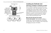
...and rout the power cable. Bottom of the Fishfinder and protect it easily while operating the vessel. Mounting the Bracket Assembly Tool List (not included)-drill, screwdriver (Phillips or standard), three #8 pan-head machine bolts ...nuts and washers, and a 5/32" drill bit; When installing the mounting bracket, be sure to allow room to extreme temperature conditions. INSTALLING YOUR FISHFINDER > INSTALLING THE FISHFINDER UNIT Drill pilot holes here. OK Installing the Fishfinder Unit ...self-tapping screws and a 1/16" drill bit. 10 Fishfinder 90/140 Owner's Manual
...and rout the power cable. Bottom of the Fishfinder and protect it easily while operating the vessel. Mounting the Bracket Assembly Tool List (not included)-drill, screwdriver (Phillips or standard), three #8 pan-head machine bolts ...nuts and washers, and a 5/32" drill bit; When installing the mounting bracket, be sure to allow room to extreme temperature conditions. INSTALLING YOUR FISHFINDER > INSTALLING THE FISHFINDER UNIT Drill pilot holes here. OK Installing the Fishfinder Unit ...self-tapping screws and a 1/16" drill bit. 10 Fishfinder 90/140 Owner's Manual
Owner's Manual
Page 17
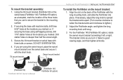
... or swivel base with the short knob. Swivel mount bracket Tilt mount bracket INSTALLING YOUR FISHFINDER > INSTALLING THE FISHFINDER UNIT To install the Fishfinder on the back of the three holes that you turn it. Fishfinder 90 option) Fishfinder 90/140 Owner's Manual 11 DO NOT OVERTIGHTEN. 4. Select a good viewing...
... or swivel base with the short knob. Swivel mount bracket Tilt mount bracket INSTALLING YOUR FISHFINDER > INSTALLING THE FISHFINDER UNIT To install the Fishfinder on the back of the three holes that you turn it. Fishfinder 90 option) Fishfinder 90/140 Owner's Manual 11 DO NOT OVERTIGHTEN. 4. Select a good viewing...

Owner's Manual
Page 19
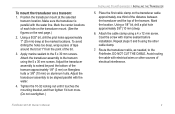
... be working properly gradually increase the boat's speed observing the sonar's operation. Return the boat to eliminate the degradation. 4. To test the transom mount installation: 1. Fishfinder 90/140 Owner's Manual 13 If the signal does not improve, it extends another 1/8" below the water line. If the sonar signal suddenly is...
... be working properly gradually increase the boat's speed observing the sonar's operation. Return the boat to eliminate the degradation. 4. To test the transom mount installation: 1. Fishfinder 90/140 Owner's Manual 13 If the signal does not improve, it extends another 1/8" below the water line. If the sonar signal suddenly is...

Owner's Manual
Page 25
... your product when you . Optional Accessories Purchase the following optional accessories on the Garmin Web site: Swivel mount for 30 minutes) Temperature Range: +5°F to 158°F (-15°C to 70°C) Fishfinder 90/140 Owner's Manual Internal memory backup to retain user settings Input: 10 to ... Case: Fully Gasketed, high-impact plastic alloy Waterproof: IEC 529, level IPX-7 (submerged to 1 meter for the Fishfinder 90-allows your Fishfinder 90 to tilt and swivel on its mounting bracket. makes your fishfinder flush on the bulkhead or cabin wall.
... your product when you . Optional Accessories Purchase the following optional accessories on the Garmin Web site: Swivel mount for 30 minutes) Temperature Range: +5°F to 158°F (-15°C to 70°C) Fishfinder 90/140 Owner's Manual Internal memory backup to retain user settings Input: 10 to ... Case: Fully Gasketed, high-impact plastic alloy Waterproof: IEC 529, level IPX-7 (submerged to 1 meter for the Fishfinder 90-allows your Fishfinder 90 to tilt and swivel on its mounting bracket. makes your fishfinder flush on the bulkhead or cabin wall.

Owner's Manual
Page 30
...64257;sh ID 17 Whiteline 17 H hardness of the bottom 3 I installing the Fishfinder unit 10 the transducer 6 the unit on the mount bracket 11 the wiring harness 12 your Fishfinder 5 K key arrow 14 enter 14 menu 14 L language setting 18 limited warranty 21 ...location, installation 10 M menu main 15 setup 16 menu key 14 mounting the bracket assembly 10 mounting the transducer on a transom 9 mounting the transducer on a trolling motor 6 N narrow beam 2 numbers 18 battery 18 water temperature 18 O optional accessories 19 P ...
...64257;sh ID 17 Whiteline 17 H hardness of the bottom 3 I installing the Fishfinder unit 10 the transducer 6 the unit on the mount bracket 11 the wiring harness 12 your Fishfinder 5 K key arrow 14 enter 14 menu 14 L language setting 18 limited warranty 21 ...location, installation 10 M menu main 15 setup 16 menu key 14 mounting the bracket assembly 10 mounting the transducer on a transom 9 mounting the transducer on a trolling motor 6 N narrow beam 2 numbers 18 battery 18 water temperature 18 O optional accessories 19 P ...

Owner's Manual
Page 31
... returns 3 surface clutter 4 swivel mount bracket 11 T temperature number 18 temperature units 18 testing the transom mount installation 13 transducer 1 assembling 6 installing 6 mounting on a transom 7 mounting on a trolling motor 6 transom mount installation 13 U units 18 depth ...18 temperature 18 V view 16 W warning statement vi warranty, limited 21 water immersion 20 water temperature number 18 weakest sonar returns 3 whiteline 17 wide beam 2 wiring harness 12 Z zoom 16 Fishfinder 90...
... returns 3 surface clutter 4 swivel mount bracket 11 T temperature number 18 temperature units 18 testing the transom mount installation 13 transducer 1 assembling 6 installing 6 mounting on a transom 7 mounting on a trolling motor 6 transom mount installation 13 U units 18 depth ...18 temperature 18 V view 16 W warning statement vi warranty, limited 21 water immersion 20 water temperature number 18 weakest sonar returns 3 whiteline 17 wide beam 2 wiring harness 12 Z zoom 16 Fishfinder 90...
Flush Mount Template
Page 1
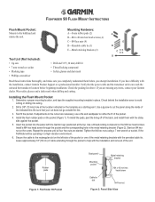
... Insert the pocket into wiring. 2. Secure the cable to refine the fit of the indicated line. FISHFINDER 90 FLUSH MOUNT INSTRUCTIONS Flush Mount Pocket: Mounts to help with the installation and removal of the metal retaining brackets with the provided cable tie. If you are missing...cable and the transducer cable can reach the unit and the transducer location before you have difficulty with the installation, contact Garmin Product Support or a professional installer. Test fit the pocket. If adjustments to the cutout are started. Leave approximately 18" ...
... Insert the pocket into wiring. 2. Secure the cable to refine the fit of the indicated line. FISHFINDER 90 FLUSH MOUNT INSTRUCTIONS Flush Mount Pocket: Mounts to help with the installation and removal of the metal retaining brackets with the provided cable tie. If you are missing...cable and the transducer cable can reach the unit and the transducer location before you have difficulty with the installation, contact Garmin Product Support or a professional installer. Test fit the pocket. If adjustments to the cutout are started. Leave approximately 18" ...

