Hardware Guide
Page 3
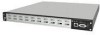
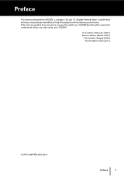
First edition (February 2007) Second edition (March 2007) Third edition (August 2010) Fourth edition (April 2011) © PFU LIMITED 2007-2011 Preface 1 Preface You have purchased the XG2000, a compact, 20 port 10 Gigabit Ethernet layer 2 switch that achieves unsurpassed standards of high throughput and low-latency performance. This manual explains the procedures required to install your XG2000 and should be read and understood before you start using your XG2000.
First edition (February 2007) Second edition (March 2007) Third edition (August 2010) Fourth edition (April 2011) © PFU LIMITED 2007-2011 Preface 1 Preface You have purchased the XG2000, a compact, 20 port 10 Gigabit Ethernet layer 2 switch that achieves unsurpassed standards of high throughput and low-latency performance. This manual explains the procedures required to install your XG2000 and should be read and understood before you start using your XG2000.
Hardware Guide
Page 5
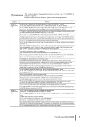
... you remove a power plug from its side or stack up multiple XG2000s. A power plug damaged by yourself. Continued use under these conditions risks lightning damage to the XG2000, and may cause an electric shock and fire.(P.34) Do not bundle the power cords. Unplug the XG2000 during thunder-storms. Continued use under ... on the XG2000. If too many devices are connected, the power socket may cause a fire. Doing so increases the heat density, and may overheat and cause a fire. Do not install the XG2000 in around where children can explode. If burnt, the XG2000 can find them...
... you remove a power plug from its side or stack up multiple XG2000s. A power plug damaged by yourself. Continued use under these conditions risks lightning damage to the XG2000, and may cause an electric shock and fire.(P.34) Do not bundle the power cords. Unplug the XG2000 during thunder-storms. Continued use under ... on the XG2000. If too many devices are connected, the power socket may cause a fire. Doing so increases the heat density, and may overheat and cause a fire. Do not install the XG2000 in around where children can explode. If burnt, the XG2000 can find them...
Hardware Guide
Page 6
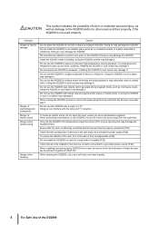
...the temperature goes up multiple XG2000s. Do not install the XG2000 in such a place may damage it . Using the XG2000 in an unstable place (such as microwave ovens. Install the XG2000 inside the rack is properly exhausted.(P.26) Check that the configuration of devices in areas ...use the XG2000 in the rack does not overload the power supply.(P.26) To ensure the stability of electric shock Danger when rackmounting Danger when cleaning Caution Do not place the XG2000 on the XG2000. At least two people should work on its side or stack up and down suddenly. Do not use the XG2000...
...the temperature goes up multiple XG2000s. Do not install the XG2000 in such a place may damage it . Using the XG2000 in an unstable place (such as microwave ovens. Install the XG2000 inside the rack is properly exhausted.(P.26) Check that the configuration of devices in areas ...use the XG2000 in the rack does not overload the power supply.(P.26) To ensure the stability of electric shock Danger when rackmounting Danger when cleaning Caution Do not place the XG2000 on the XG2000. At least two people should work on its side or stack up and down suddenly. Do not use the XG2000...
Hardware Guide
Page 7
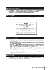
... than the original purchase price. • Fujitsu and its partners do not approve of any errors or data loss arising from use of this warning label. For security A default login password is set before the XG2000 is no responsibility for any authorized firmware upgrades, for a replacement label. For Safe Use of the XG2000 is required, contact the vendor's service department. If maintenance is approximately five...
... than the original purchase price. • Fujitsu and its partners do not approve of any errors or data loss arising from use of this warning label. For security A default login password is set before the XG2000 is no responsibility for any authorized firmware upgrades, for a replacement label. For Safe Use of the XG2000 is required, contact the vendor's service department. If maintenance is approximately five...

Hardware Guide
Page 8
... XG2000 This equipment generates uses, and can cause the device or its LAN port to operate falsely or to become charged with the limits for compliance could void the user's authority to operate the equipment. Connecting a statically charged twisted pair cable to a device can radiate radio frequency energy and. Electromagnetic compatibility (USA) FCC PART 15B Class A FCC WARNING: Changes...
... XG2000 This equipment generates uses, and can cause the device or its LAN port to operate falsely or to become charged with the limits for compliance could void the user's authority to operate the equipment. Connecting a statically charged twisted pair cable to a device can radiate radio frequency energy and. Electromagnetic compatibility (USA) FCC PART 15B Class A FCC WARNING: Changes...
Hardware Guide
Page 9
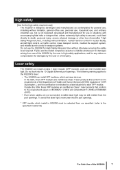
... level required. The following warning applies to the XG2000's laser: • The XG2000 can emit invisible laser light. Laser safety The XG2000 can install a class 1 laser module (XFP module), and can install XFP modules, which install in XG2000 must be still emitted from our specified. (refer to the specified module list) For Safe Use of the XG2000 by the user or a third party. In the USA, these...
... level required. The following warning applies to the XG2000's laser: • The XG2000 can emit invisible laser light. Laser safety The XG2000 can install a class 1 laser module (XFP module), and can install XFP modules, which install in XG2000 must be still emitted from our specified. (refer to the specified module list) For Safe Use of the XG2000 by the user or a third party. In the USA, these...
Hardware Guide
Page 10
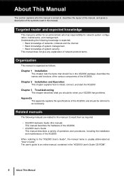
... network protocol terms. Organization This manual is organized as required. • XG2000 Hardware Guide (this manual. Consult them as follows. Chapter 3 Troubleshooting This chapter describes what you should do when your XG2000 has problems. Appendix This appendix explains the specifications of the XG2000. When referring to as "User's Guide". Related manuals The following knowledge is an online manual, contained in this manual) This manual describes the hardware of the XG2000...
... network protocol terms. Organization This manual is organized as required. • XG2000 Hardware Guide (this manual. Consult them as follows. Chapter 3 Troubleshooting This chapter describes what you should do when your XG2000 has problems. Appendix This appendix explains the specifications of the XG2000. When referring to as "User's Guide". Related manuals The following knowledge is an online manual, contained in this manual) This manual describes the hardware of the XG2000...
Hardware Guide
Page 13
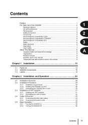
... used in this manual 9 Chapter 1 Installation 13 1-1 Parts List ...14 1-2 XG2000 Components 16 1-3 Labels ...19 Chapter 2 Installation and Operation 23 2-1 Installation Overview 24 2-2 Installation Procedure 25 2-2-1 Installation requirements 25 2-2-2 Installing the XG2000 in a rack 26 2-2-3 Uninstalling the XG2000 from a rack 30 2-3 Installation of XFP modules 31 2-3-1 Installing the XFP modules 31 2-3-2 Uninstalling the XFP modules 32 2-4 Cable Connection 33 2-4-1 Connecting the fiber optic cables 33 2-4-2 Connecting the power cords 34 2-5 Basic Operation 35 2-5-1 Turning...
... used in this manual 9 Chapter 1 Installation 13 1-1 Parts List ...14 1-2 XG2000 Components 16 1-3 Labels ...19 Chapter 2 Installation and Operation 23 2-1 Installation Overview 24 2-2 Installation Procedure 25 2-2-1 Installation requirements 25 2-2-2 Installing the XG2000 in a rack 26 2-2-3 Uninstalling the XG2000 from a rack 30 2-3 Installation of XFP modules 31 2-3-1 Installing the XFP modules 31 2-3-2 Uninstalling the XFP modules 32 2-4 Cable Connection 33 2-4-1 Connecting the fiber optic cables 33 2-4-2 Connecting the power cords 34 2-5 Basic Operation 35 2-5-1 Turning...
Hardware Guide
Page 14
Chapter 3 Troubleshooting 37 3-1 Start-up Problems 38 3-2 Hardware Problems 39 Appendix 41 Appendix-A Specifications 42 A.1 Product Specifications 42 A.2 Installation Specifications 42 Appendix-B China RoHS Declaration for the XG2000 43 Appendix-C EC Declaration for the XG2000 44 12 Contents
Chapter 3 Troubleshooting 37 3-1 Start-up Problems 38 3-2 Hardware Problems 39 Appendix 41 Appendix-A Specifications 42 A.1 Product Specifications 42 A.2 Installation Specifications 42 Appendix-B China RoHS Declaration for the XG2000 43 Appendix-C EC Declaration for the XG2000 44 12 Contents
Hardware Guide
Page 16
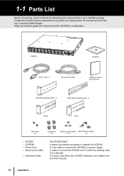
XG2000 CD-ROM Power code × 2 Serial Cross Cable Hardware Guide (this manual). 14 Installation A cable to connect the XG2000 to a PC when the settings need to operate the XG2000. Keep the hardware guide (this manual) and the CD-ROM in your XG2000 package. Contains documents necessary to be adjusted. A manual describing the XG2000 hardware and related matters (this manual) Rack Mounting Brackets × 2 Rack Mounting Bracket B × 2 Rail R Rail L Rack Nuts × 8 Cage Nuts × 8 Rack Screws (Small) Rack Screws...
XG2000 CD-ROM Power code × 2 Serial Cross Cable Hardware Guide (this manual). 14 Installation A cable to connect the XG2000 to a PC when the settings need to operate the XG2000. Keep the hardware guide (this manual) and the CD-ROM in your XG2000 package. Contains documents necessary to be adjusted. A manual describing the XG2000 hardware and related matters (this manual) Rack Mounting Brackets × 2 Rack Mounting Bracket B × 2 Rail R Rail L Rack Nuts × 8 Cage Nuts × 8 Rack Screws (Small) Rack Screws...
Hardware Guide
Page 18
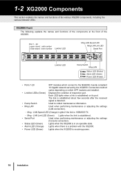
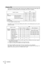
... LEDs (Green) • Dump Switch • Mng-LAN XFP modules which XFP modules are installed. Displays the condition of the XG2000. Used to the IEEE802.3 ae/ak compliant 10 Gigabit network served by the XG2000. LAN Link LED (Green) Lights when the link is established. • Serial Port Used when performing maintenance or adjusting the settings (Console connection). • Status LED (Green) Lights when the XG2000 is in an operable state. • Alarm LED (Orange) Lights when there is a problem...
... LEDs (Green) • Dump Switch • Mng-LAN XFP modules which XFP modules are installed. Displays the condition of the XG2000. Used to the IEEE802.3 ae/ak compliant 10 Gigabit network served by the XG2000. LAN Link LED (Green) Lights when the link is established. • Serial Port Used when performing maintenance or adjusting the settings (Console connection). • Status LED (Green) Lights when the XG2000 is in an operable state. • Alarm LED (Orange) Lights when there is a problem...
Hardware Guide
Page 19
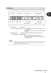
.... Power Supply LED (Green/Orange) Green LED lights when the XG2000 is a problem with the Rear Fan Unit. • Power Supply Unit Supplies power to avoid a negative effect on . Attention In order to the XG2000 (includes an exhaust fan). - mal operation. XG2000 rear The following explains the names and functions of the XG2000. Orange LED when there is in nor- Rear Fan Unit Rear Fan Unit Power Supply Unit Power Supply Unit 1 Rear Fan LED Rear Fan LED Power Inlet Power Supply LED Power...
.... Power Supply LED (Green/Orange) Green LED lights when the XG2000 is a problem with the Rear Fan Unit. • Power Supply Unit Supplies power to avoid a negative effect on . Attention In order to the XG2000 (includes an exhaust fan). - mal operation. XG2000 rear The following explains the names and functions of the XG2000. Orange LED when there is in nor- Rear Fan Unit Rear Fan Unit Power Supply Unit Power Supply Unit 1 Rear Fan LED Rear Fan LED Power Inlet Power Supply LED Power...
Hardware Guide
Page 20
... problems other than those that the XG2000 will depend on failed part Problem detected Startup error Rear fan error On ---*3 Blinking --- On On ---*4 Rear Fan LED: Orange Power fan error On On ---*4 Power Supply LED: Orange No AC supply *2 On On ---*4 Power Supply LED: Orange Power supply error On On ---*4 Power Supply LED: Orange Voltage error On On ---*4 --- System dump in the event log. For details of the event log, refer to identify the trouble: XG2000 Condition Power Alarm LED Status LED on the state of the Status LED...
... problems other than those that the XG2000 will depend on failed part Problem detected Startup error Rear fan error On ---*3 Blinking --- On On ---*4 Rear Fan LED: Orange Power fan error On On ---*4 Power Supply LED: Orange No AC supply *2 On On ---*4 Power Supply LED: Orange Power supply error On On ---*4 Power Supply LED: Orange Voltage error On On ---*4 --- System dump in the event log. For details of the event log, refer to identify the trouble: XG2000 Condition Power Alarm LED Status LED on the state of the Status LED...
Hardware Guide
Page 23
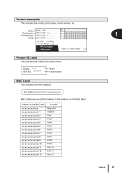
Model ****** Part Number Serial Number PA P* * * * * * 1 DATE **** ** ** 100-240V 1 50/60Hz *** ***A / INPUT **kg Product ID Label This indicates the model and serial number. MODEL ***** SER. NO ********* Model Serial Number MAC Label This indicates the MAC address: MAC addresses are allotted relative to the address on the MAC label: Address on the MAC label xx:xx...:xx:xx:xx+13 Location Mng-LAN XG2000 Port 1 Port 2 Port3 Port 4 Port 5 Port 6 Port 7 Port 8 Port 9 Port 10 Port 11 Port 12 Labels 21 Product nameplate This indicates the model, part number, serial number, etc.
Model ****** Part Number Serial Number PA P* * * * * * 1 DATE **** ** ** 100-240V 1 50/60Hz *** ***A / INPUT **kg Product ID Label This indicates the model and serial number. MODEL ***** SER. NO ********* Model Serial Number MAC Label This indicates the MAC address: MAC addresses are allotted relative to the address on the MAC label: Address on the MAC label xx:xx...:xx:xx:xx+13 Location Mng-LAN XG2000 Port 1 Port 2 Port3 Port 4 Port 5 Port 6 Port 7 Port 8 Port 9 Port 10 Port 11 Port 12 Labels 21 Product nameplate This indicates the model, part number, serial number, etc.

Hardware Guide
Page 26
... Safe Use of the XG2000", "2-2 Installation Procedure" 3 Installation of the XFP modules Install the XFP modules in the XG2000. 2-1 Installation Overview This section reviews the flow of work as follows: 1 Check the components "1-1 Parts List" 2 Check the set up normally. Install the XG2000 and the proceed with normal operation as the user proceeds from installation to the XG2000. "2-3-1 Installing the XFP modules" 4 Connect the cables to the XG2000 Connect the required fiber optic cables and power cords to operation of the XG2000. "2-4 Cable Connection" 5 Check...
... Safe Use of the XG2000", "2-2 Installation Procedure" 3 Installation of the XFP modules Install the XFP modules in the XG2000. 2-1 Installation Overview This section reviews the flow of work as follows: 1 Check the components "1-1 Parts List" 2 Check the set up normally. Install the XG2000 and the proceed with normal operation as the user proceeds from installation to the XG2000. "2-3-1 Installing the XFP modules" 4 Connect the cables to the XG2000 Connect the required fiber optic cables and power cords to operation of the XG2000. "2-4 Cable Connection" 5 Check...

Hardware Guide
Page 28
... temperature, particularly if the rack contains multiple units. Special care should not be used , for all the installed units are correctly grounded. Set up requirements Only use the XG2000 under the temperature, humidity and other environmental conditions specified in a rack may cause the entire rack to supply sufficient power for example). Make sure that adequate ventilation is used . When multiple devices are not obstructed...
... temperature, particularly if the rack contains multiple units. Special care should not be used , for all the installed units are correctly grounded. Set up requirements Only use the XG2000 under the temperature, humidity and other environmental conditions specified in a rack may cause the entire rack to supply sufficient power for example). Make sure that adequate ventilation is used . When multiple devices are not obstructed...
Hardware Guide
Page 37
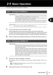
Connect the power cord to the power outlet. Insert the plug at the other end of the power cord into the power socket. The Alarm LED (Orange) should turn on for safety reasons. To make this case, the state of data in Refer the "XG2000 User's Guide". 2. Execute the "system shutdown" command. CAUTION Do not move, shock, or vibrate the XG2000 while it is disconnected...
Connect the power cord to the power outlet. Insert the plug at the other end of the power cord into the power socket. The Alarm LED (Orange) should turn on for safety reasons. To make this case, the state of data in Refer the "XG2000 User's Guide". 2. Execute the "system shutdown" command. CAUTION Do not move, shock, or vibrate the XG2000 while it is disconnected...
Hardware Guide
Page 40
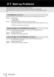
... Troubleshooting Alarm LED lights, but the XG2000 does not start up [Symptom] The XG2000 has not started within a few minutes of the XG2000 turned on . The Status LED keeps blinking. [Cause] Probable hardware failure. [Action] Contact the vendor's service department. If the cause of these match your problem. 3-1 Start-up Problems The following with the corresponding number; 1 Check that can occur. Check if any of the error cannot...
... Troubleshooting Alarm LED lights, but the XG2000 does not start up [Symptom] The XG2000 has not started within a few minutes of the XG2000 turned on . The Status LED keeps blinking. [Cause] Probable hardware failure. [Action] Contact the vendor's service department. If the cause of these match your problem. 3-1 Start-up Problems The following with the corresponding number; 1 Check that can occur. Check if any of the error cannot...
Hardware Guide
Page 41
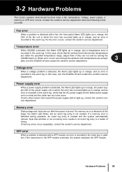
... the AC power supply for the failed power supply unit is recorded in the event log. If a fan error occurs, contact the vendor's service department. When error occurs even though the ambient rack temperatures are not and try turning the XG2000 back on. In this case, turn the XG2000 off and contact the vendor's service department. XFP error When a problem is detected with a fan, the front panel Alarm LED lights up...
... the AC power supply for the failed power supply unit is recorded in the event log. If a fan error occurs, contact the vendor's service department. When error occurs even though the ambient rack temperatures are not and try turning the XG2000 back on. In this case, turn the XG2000 off and contact the vendor's service department. XFP error When a problem is detected with a fan, the front panel Alarm LED lights up...
Hardware Guide
Page 44
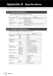
... Temperature gradient XG2000 on XG2000 off Ambient dust Ambient noise Electromagnetic compatibility Service area Installation Front Rear Specifications 440mm 480mm 43.8mm 14kg for XFP modules) RS-232C D-SUB9 × 1 Console connection port 10BASE-T/100BASE-TX × 1 Power (Green), Alarm (Orange), Status (Green), Rear fan × 2, Power supply units × 2 A.2 Installation Specifications The installation specifications of XG2000. A.1 Product Specifications The product specifications of the XG2000 are as follows: Items 10 Gigabit ports Serial Port Management LAN Indicators...
... Temperature gradient XG2000 on XG2000 off Ambient dust Ambient noise Electromagnetic compatibility Service area Installation Front Rear Specifications 440mm 480mm 43.8mm 14kg for XFP modules) RS-232C D-SUB9 × 1 Console connection port 10BASE-T/100BASE-TX × 1 Power (Green), Alarm (Orange), Status (Green), Rear fan × 2, Power supply units × 2 A.2 Installation Specifications The installation specifications of XG2000. A.1 Product Specifications The product specifications of the XG2000 are as follows: Items 10 Gigabit ports Serial Port Management LAN Indicators...
