
Manual/User Guide
Page 35
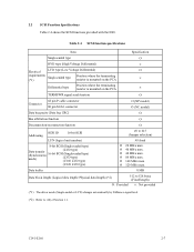
... IDD. Data buffer 8 MB Data block length (Logical data length=Physical data length) (*2) 512 to 528 bytes (Fixed length) Ο : Provided × : Not provided (*1) The driver mode (Single-ended or LVD) changes automatically by Diffsence signal level. (*2) Refer to #15 (Jumper selection) #0 fixed Ο 20 MB/s max. Ο 40 MB/s max...
... IDD. Data buffer 8 MB Data block length (Logical data length=Physical data length) (*2) 512 to 528 bytes (Fixed length) Ο : Provided × : Not provided (*1) The driver mode (Single-ended or LVD) changes automatically by Diffsence signal level. (*2) Refer to #15 (Jumper selection) #0 fixed Ο 20 MB/s max. Ο 40 MB/s max...
Manual/User Guide
Page 56
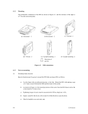
... e) Must be handled on mounting (1) Mounting frame structure Special attention must be secured with an embossed structure, or the like. d) Impact caused by the electric driver must be 5.0 mm or less. Mount the IDD with making a gap of 2.5 mm or more between the IDD and the frame of the screw from...
... e) Must be handled on mounting (1) Mounting frame structure Special attention must be secured with an embossed structure, or the like. d) Impact caused by the electric driver must be 5.0 mm or less. Mount the IDD with making a gap of 2.5 mm or more between the IDD and the frame of the screw from...
Manual/User Guide
Page 58
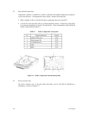
...surface temperature does not exceed 60°C. • Cool the PCA side especially with ambient temperature measured 3 cm from the disk drive. These measurement results should be within a criteria listed in Figures 4.7. 4-6 C141-E166 Table 4.1 Surface temperature check point No.... Confirm the cooling effect by measuring temperature of DE cover 2 Read channel LSI 3 VCM/SPM Driver 4 HDC 5 MPU Criteria 60°C 88°C 92°C 91°C 91°C 3 1 4 5 2 Figure 4.6 Surface temperature measurement points...
...surface temperature does not exceed 60°C. • Cool the PCA side especially with ambient temperature measured 3 cm from the disk drive. These measurement results should be within a criteria listed in Figures 4.7. 4-6 C141-E166 Table 4.1 Surface temperature check point No.... Confirm the cooling effect by measuring temperature of DE cover 2 Read channel LSI 3 VCM/SPM Driver 4 HDC 5 MPU Criteria 60°C 88°C 92°C 91°C 91°C 3 1 4 5 2 Figure 4.6 Surface temperature measurement points...
Manual/User Guide
Page 85
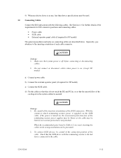
... power is off before connecting or disconnecting cables. 2. c) Connect the SCSI cable. When the recommended parts listed in Table 4.2 are described below. 4) When an electric driver is in use, less than device specifications must be careful of the connection position of the cable. To connect SCSI devices, be used , inserting the...
... power is off before connecting or disconnecting cables. 2. c) Connect the SCSI cable. When the recommended parts listed in Table 4.2 are described below. 4) When an electric driver is in use, less than device specifications must be careful of the connection position of the cable. To connect SCSI devices, be used , inserting the...


