
Manual/User Guide
Page 5
... into a host computer system. PREFACE This manual describes the MAN3735MC/MP, MAN3367MC/MP, MAN3184MC/MP (hereafter, MAN series), 3.5 type fixed disk drives with an embedded SCSI controller. This manual is written for users who have a basic understanding of the MAN series disk drives and their standard features, hardware, and system configuration. Chapter 3 DATA FORMAT This chapter...
... into a host computer system. PREFACE This manual describes the MAN3735MC/MP, MAN3367MC/MP, MAN3184MC/MP (hereafter, MAN series), 3.5 type fixed disk drives with an embedded SCSI controller. This manual is written for users who have a basic understanding of the MAN series disk drives and their standard features, hardware, and system configuration. Chapter 3 DATA FORMAT This chapter...
Manual/User Guide
Page 6
Indicates iv C141-E128-01EN DANGER DANGER indicates that describes the electrical requirements of model names and product numbers, and SCSI interface functions. The model numbers have a suffix that personal injury will occur if the user does not perform the procedure correctly. WARNING WARNING ...supplementary information, including the locations of mounting setting terminals and connectors, a list of setting items, the signal assignments of interface connectors, lists of the SCSI interface between host system and disk drive, the data formatted at the factory and device type.
Indicates iv C141-E128-01EN DANGER DANGER indicates that describes the electrical requirements of model names and product numbers, and SCSI interface functions. The model numbers have a suffix that personal injury will occur if the user does not perform the procedure correctly. WARNING WARNING ...supplementary information, including the locations of mounting setting terminals and connectors, a list of setting items, the signal assignments of interface connectors, lists of the SCSI interface between host system and disk drive, the data formatted at the factory and device type.
Manual/User Guide
Page 7
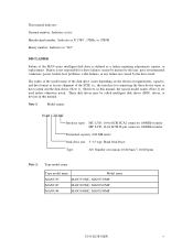
Fujitsu is not responsible for connecting the three device types or host system and the disk drives (Note 1). The suffix of the model name of the disk drive varies depending on the electrical requirements, capacity, and data format at factory shipment of rotations 10,025min-1... MAN3367 MAN3367MC, MAN3367MP MAN3184 MAN3184MC, MAN3184MP C141-E128-01EN v Note 1: Model names M AN 3 735 MC Interface types MC: LVD, 16-bit SCSI SCA2 connector 160MHz transfer MP: LVD, 16-bit SCSI 68 pin connector 160MHz transfer Formatted capacity (100 MB units) Disk drive size 3: 3.5 type. This...
Fujitsu is not responsible for connecting the three device types or host system and the disk drives (Note 1). The suffix of the model name of the disk drive varies depending on the electrical requirements, capacity, and data format at factory shipment of rotations 10,025min-1... MAN3367 MAN3367MC, MAN3367MP MAN3184 MAN3184MC, MAN3184MP C141-E128-01EN v Note 1: Model names M AN 3 735 MC Interface types MC: LVD, 16-bit SCSI SCA2 connector 160MHz transfer MP: LVD, 16-bit SCSI 68 pin connector 160MHz transfer Formatted capacity (100 MB units) Disk drive size 3: 3.5 type. This...
Manual/User Guide
Page 9
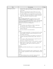
... to the device. 2. Damage 6-6 Do not open the disk enclosure in the field because it is required to clean a disk drive assembly. 5. C141-E128-01EN vii Fujitsu does not assume responsibility if data is destroyed during disk drive operation. 3. Data loss 6-4 When the SEND DIAGNOSTIC command ...4. This operation is a completely sealed room. Task Mounting Installation Alert message Page protection fuse of the cable. To connect SCSI devices, be careful of the connection position of the terminating resistor power supplier may be blown or the cable may be burnt...
... to the device. 2. Damage 6-6 Do not open the disk enclosure in the field because it is required to clean a disk drive assembly. 5. C141-E128-01EN vii Fujitsu does not assume responsibility if data is destroyed during disk drive operation. 3. Data loss 6-4 When the SEND DIAGNOSTIC command ...4. This operation is a completely sealed room. Task Mounting Installation Alert message Page protection fuse of the cable. To connect SCSI devices, be careful of the connection position of the terminating resistor power supplier may be blown or the cable may be burnt...
Manual/User Guide
Page 10
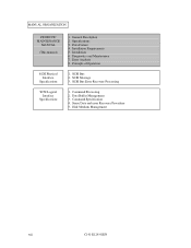
MANUAL ORGANIZATION PRODUCT/ MAINTENANCE MANUAL (This manual) 1. Specifications 3. Diagnostics and Maintenance 7. Data Buffer Management 3. Installation Requirements 5. SCSI Bus 2. SCSI Message 3. Command Specification 4. Principle of Operation SCSI Physical Interface Specifications 1. Data Format 4. Error Analysis 8. Sense Data and error Recovery Procedure 5. General Description 2. SCSI Bus Error Recovery Processing SCSI Logical Interface Specifications 1. Disk Medium Management viii C141-E128-01EN Installation 6. Command Processing 2.
MANUAL ORGANIZATION PRODUCT/ MAINTENANCE MANUAL (This manual) 1. Specifications 3. Diagnostics and Maintenance 7. Data Buffer Management 3. Installation Requirements 5. SCSI Bus 2. SCSI Message 3. Command Specification 4. Principle of Operation SCSI Physical Interface Specifications 1. Data Format 4. Error Analysis 8. Sense Data and error Recovery Procedure 5. General Description 2. SCSI Bus Error Recovery Processing SCSI Logical Interface Specifications 1. Disk Medium Management viii C141-E128-01EN Installation 6. Command Processing 2.
Manual/User Guide
Page 12
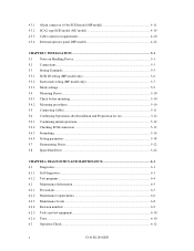
... Mounting procedures...5-10 5.5 Connecting Cables...5-11 5.6 Confirming Operations after Installation and Preparation for use 5-12 5.6.1 Confirming initial operations 5-12 5.6.2 Checking SCSI connection 5-13 5.6.3 Formatting ...5-16 5.6.4 Setting parameters ...5-18 5.7 Dismounting Drives...5-22 5.8 Spare Disk Drive ...5-22 CHAPTER 6 DIAGNOSTICS AND MAINTENANCE 6-1 6.1 Diagnostics ...6-1 6.1.1 Self-diagnostics ...6-1 6.1.2 Test programs ...6-4 6.2 Maintenance Information 6-5 6.2.1 Precautions ...6-5 6.2.2 Maintenance requirements 6-6 6.2.3 Maintenance levels ...6-8 6.2.4 Revision numbers...
... Mounting procedures...5-10 5.5 Connecting Cables...5-11 5.6 Confirming Operations after Installation and Preparation for use 5-12 5.6.1 Confirming initial operations 5-12 5.6.2 Checking SCSI connection 5-13 5.6.3 Formatting ...5-16 5.6.4 Setting parameters ...5-18 5.7 Dismounting Drives...5-22 5.8 Spare Disk Drive ...5-22 CHAPTER 6 DIAGNOSTICS AND MAINTENANCE 6-1 6.1 Diagnostics ...6-1 6.1.1 Self-diagnostics ...6-1 6.1.2 Test programs ...6-4 6.2 Maintenance Information 6-5 6.2.1 Precautions ...6-5 6.2.2 Maintenance requirements 6-6 6.2.3 Maintenance levels ...6-8 6.2.4 Revision numbers...
Manual/User Guide
Page 13
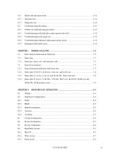
...12 Diagnostic test ...6-12 Troubleshooting Procedures 6-13 Outline of troubleshooting procedures 6-13 Troubleshooting with disk drive replacement in the field 6-13 Troubleshooting at the repair site 6-15 Troubleshooting with parts replacement...2x-xx), (5-3D-00), (5-90-00), (B-47-xx), (B-49-00), (B-4D-xx) and (B-4E-00): SCSI interface error 7-4 CHAPTER 8 PRINCIPLE OF OPERATION 8-1 8.1 Outline ...8-1 8.2 Disk Drive Configuration 8-1 8.2.1 Disks ...8-2 8.2.2 Heads ...8-2 8.2.3 Spindle mechanism...8-2 8.2.4 Actuator ...8-2 8.2.5 Air filters ...8-2 8.3 Circuit Configuration...8-3 8.4 Power-On...
...12 Diagnostic test ...6-12 Troubleshooting Procedures 6-13 Outline of troubleshooting procedures 6-13 Troubleshooting with disk drive replacement in the field 6-13 Troubleshooting at the repair site 6-15 Troubleshooting with parts replacement...2x-xx), (5-3D-00), (5-90-00), (B-47-xx), (B-49-00), (B-4D-xx) and (B-4E-00): SCSI interface error 7-4 CHAPTER 8 PRINCIPLE OF OPERATION 8-1 8.1 Outline ...8-1 8.2 Disk Drive Configuration 8-1 8.2.1 Disks ...8-2 8.2.2 Heads ...8-2 8.2.3 Spindle mechanism...8-2 8.2.4 Actuator ...8-2 8.2.5 Air filters ...8-2 8.3 Circuit Configuration...8-3 8.4 Power-On...
Manual/User Guide
Page 15
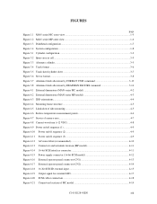
FIGURES page Figure 1.1 MAN series MC outer view ...1-5 Figure 1.2 MAN series MP outer view...1-6 Figure 1.3 Disk/head configuration...1-7 Figure 1.4 System configuration ...1-8 Figure 3.1 Cylinder configuration ...3-2 Figure 3.2 Spare area in cell...3-5 Figure 3.3 Alternate cylinder...3-5 Figure 3.4 Track ...(16-bit SCSI model 4-12 Figure 4.16 External operator panel connector (CN1 4-13 Figure 4.17 External operator panel connector (CN2 4-14 Figure 4.18 16-bit SCSI ID external input 4-15 Figure 4.19 Output signal for external LED 4-17 Figure 4.20 SCSI cables connection...4-18 Figure 4.21...
FIGURES page Figure 1.1 MAN series MC outer view ...1-5 Figure 1.2 MAN series MP outer view...1-6 Figure 1.3 Disk/head configuration...1-7 Figure 1.4 System configuration ...1-8 Figure 3.1 Cylinder configuration ...3-2 Figure 3.2 Spare area in cell...3-5 Figure 3.3 Alternate cylinder...3-5 Figure 3.4 Track ...(16-bit SCSI model 4-12 Figure 4.16 External operator panel connector (CN1 4-13 Figure 4.17 External operator panel connector (CN2 4-14 Figure 4.18 16-bit SCSI ID external input 4-15 Figure 4.19 Output signal for external LED 4-17 Figure 4.20 SCSI cables connection...4-18 Figure 4.21...
Manual/User Guide
Page 17
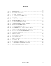
... Table 6.1 Self-diagnostic functions...6-1 Table 6.2 System-level field troubleshooting 6-14 Table 6.3 Disk drive troubleshooting...6-15 Table 7.1 Definition of sense data...7-3 Table B.1 Setting terminal: CN2 ...B-2 Table C.1 SCSI connector (SCA2 type LVD 16-bit SCSI): CN1 C-2 Table C.2 SCSI connector (68 pin type LVD 16-bit SCSI): CN1 C-3 Table D.1 MAN series model names and product numbers D-2 C141-E128-01EN...
... Table 6.1 Self-diagnostic functions...6-1 Table 6.2 System-level field troubleshooting 6-14 Table 6.3 Disk drive troubleshooting...6-15 Table 7.1 Definition of sense data...7-3 Table B.1 Setting terminal: CN2 ...B-2 Table C.1 SCSI connector (SCA2 type LVD 16-bit SCSI): CN1 C-2 Table C.2 SCSI connector (68 pin type LVD 16-bit SCSI): CN1 C-3 Table D.1 MAN series model names and product numbers D-2 C141-E128-01EN...
Manual/User Guide
Page 19
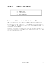
.... IDDs are high performance large capacity 3.5 type fixed disk drives with large storage capacity. The flexibility and expandability of the SCSI, as well as the powerful command set of the intelligent disk drives (IDD). C141-E128-01EN 1 - 1 Refer to construct a high-performance reliable disk subsystem with an embedded SCSI controller. The interface between the IDD and host...
.... IDDs are high performance large capacity 3.5 type fixed disk drives with large storage capacity. The flexibility and expandability of the SCSI, as well as the powerful command set of the intelligent disk drives (IDD). C141-E128-01EN 1 - 1 Refer to construct a high-performance reliable disk subsystem with an embedded SCSI controller. The interface between the IDD and host...
Manual/User Guide
Page 20
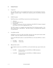
... can manipulate data through logical block addressing regardless of the physical characteristics of the disk drive. This is 160 MB/s maximum in the standard 3.5 type fixed disk drive form factor, the IDD is extremely compact. 1.1 Standard Features (1) Compactness Since the SCSI controller circuit is embedded in synchronous mode. 1 - 2 C141-E128-01EN The IDD can be...
... can manipulate data through logical block addressing regardless of the physical characteristics of the disk drive. This is 160 MB/s maximum in the standard 3.5 type fixed disk drive form factor, the IDD is extremely compact. 1.1 Standard Features (1) Compactness Since the SCSI controller circuit is embedded in synchronous mode. 1 - 2 C141-E128-01EN The IDD can be...
Manual/User Guide
Page 21
... of the data buffer, the initiator can perform the effective input/output operations with utilizing high data transfer capability of the SCSI bus regardless of actual data transfer rate of the disk drive. (7) Read-ahead cache feature After executing the READ command, the IDD reads automatically and stores (prefetches) the subsequent data blocks...
... of the data buffer, the initiator can perform the effective input/output operations with utilizing high data transfer capability of the SCSI bus regardless of actual data transfer rate of the disk drive. (7) Read-ahead cache feature After executing the READ command, the IDD reads automatically and stores (prefetches) the subsequent data blocks...
Manual/User Guide
Page 22
.... (14) High speed positioning A rotary voice coil motor achieves fast positioning. (15) Large capacity A large capacity can be obtained from 3.5 type disk drives by slipping the defective data block at initializing with large capacity can be constructed in the good space efficiency. (16) Start/Stop of 512 to...revolution delay due to facilitate testing and repair. 1 - 4 C141-E128-01EN (10) Error recovery The IDD can try to recover from errors in SCSI bus or the disk drive using its alternate data block. (12) Programmable data block length Data can be accessed in fixed-block length units.
.... (14) High speed positioning A rotary voice coil motor achieves fast positioning. (15) Large capacity A large capacity can be obtained from 3.5 type disk drives by slipping the defective data block at initializing with large capacity can be constructed in the good space efficiency. (16) Start/Stop of 512 to...revolution delay due to facilitate testing and repair. 1 - 4 C141-E128-01EN (10) Error recovery The IDD can try to recover from errors in SCSI bus or the disk drive using its alternate data block. (12) Programmable data block length Data can be accessed in fixed-block length units.
Manual/User Guide
Page 27
.... (2) Addressing of peripheral device Each SCSI device on which multiple host computers that operate as initiator or connected through the SCSI bus. A unique address (LUN: logical unit number) is a single logical unit, the selectable number of disk drive is assigned for each logical unit. ...The IDD is constructed so that the whole volume of SCSI ID and LUN are as follows: • SCSI ID: • LUN: 8-bit SCSI:Selectable from 0 to 7 (switch selectable) 16-bit SCSI:Selectable from 0 to 15 (switch...
.... (2) Addressing of peripheral device Each SCSI device on which multiple host computers that operate as initiator or connected through the SCSI bus. A unique address (LUN: logical unit number) is a single logical unit, the selectable number of disk drive is assigned for each logical unit. ...The IDD is constructed so that the whole volume of SCSI ID and LUN are as follows: • SCSI ID: • LUN: 8-bit SCSI:Selectable from 0 to 7 (switch selectable) 16-bit SCSI:Selectable from 0 to 15 (switch...
Manual/User Guide
Page 30
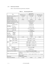
...mm 101.6 mm 146.0 mm 0.75 kg 7.5 W Cable length: 6 m max MAN3184 series 18.37 GB 1 2 30,050 7.0 W Single- Table 2.1 Function specifications Item Formatted capacity/device (*1) Number of disks Number of heads Number of cylinders (*2) Formatted capacity/track (B) Number of the IDD. Ended face...max (*6) Cable length: 1.5 m max (*7) LVD Cable length: 25 m max (*8) Cable length: 12 m max (*9) Data transfer rate (*10) Disk drive SCSI Synchronous mode 52.0 to 84.1 MB/s 160 MB/s max. 2.1.2 Function specifications Table 2.1 shows the function specifications of rotations min-1 (rpm) Average ...
...mm 101.6 mm 146.0 mm 0.75 kg 7.5 W Cable length: 6 m max MAN3184 series 18.37 GB 1 2 30,050 7.0 W Single- Table 2.1 Function specifications Item Formatted capacity/device (*1) Number of disks Number of heads Number of cylinders (*2) Formatted capacity/track (B) Number of the IDD. Ended face...max (*6) Cable length: 1.5 m max (*7) LVD Cable length: 25 m max (*8) Cable length: 12 m max (*9) Data transfer rate (*10) Disk drive SCSI Synchronous mode 52.0 to 84.1 MB/s 160 MB/s max. 2.1.2 Function specifications Table 2.1 shows the function specifications of rotations min-1 (rpm) Average ...
Manual/User Guide
Page 31
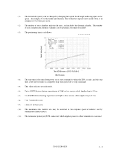
...capacity listed in the table is the time for disks to completely stop from power on 1 connection case. (*9) 1 host, 15 devices case. (*10) The maximum data transfer rate may be changed by transmission characteristics. (*11) The terminator power pin (SCSI connector) which supplies power to other terminators is ...IDD is ready, and the stop command. (*5) This value indicates at ready mode. (*6) Up to 4 SCSI devices having capacitance of 25pF or less can use cable length of up to 3.0 m. (*7) 5 to 8 SCSI devices having capacitance of 25pF or less can use cable length of up to 1.5 m. (*8) 1 on ...
...capacity listed in the table is the time for disks to completely stop from power on 1 connection case. (*9) 1 host, 15 devices case. (*10) The maximum data transfer rate may be changed by transmission characteristics. (*11) The terminator power pin (SCSI connector) which supplies power to other terminators is ...IDD is ready, and the stop command. (*5) This value indicates at ready mode. (*6) Up to 4 SCSI devices having capacitance of 25pF or less can use cable length of up to 3.0 m. (*7) 5 to 8 SCSI devices having capacitance of 25pF or less can use cable length of up to 1.5 m. (*8) 1 on ...
Manual/User Guide
Page 33
... detected during its allowable number, correction may not be performed properly. (2) Positioning error rate Positioning errors which can be distributed over the disk medium equally. (1) Unrecoverable error rate Errors which supplies power to other terminators is not used (See Section 4.3). (*7) High frequency noise is... defined as: MTBF= Operating time (hours) at the connector. (*6) The terminator power pin (SCSI connector) which cannot be 10 or less per 1015 bits. However, if error byte exceeds its life time is performed. Note: The ...
... detected during its allowable number, correction may not be performed properly. (2) Positioning error rate Positioning errors which can be distributed over the disk medium equally. (1) Unrecoverable error rate Errors which supplies power to other terminators is not used (See Section 4.3). (*7) High frequency noise is... defined as: MTBF= Operating time (hours) at the connector. (*6) The terminator power pin (SCSI connector) which cannot be 10 or less per 1015 bits. However, if error byte exceeds its life time is performed. Note: The ...
Manual/User Guide
Page 48
...E128-01EN When they are used up. See Subsection 3.1.2 for spare sectors by the MODE SELECT command at the time of the initialization of the disk. The INIT can be provided in either "spare sectors in a cylinder" or "alternate cylinders". The logical data block is allocated to the ... treatment is executed by the FORMAT UNIT command, the REASSIGN BLOCKS command, or the automatic alternate block allocation. Refer to OEM Manual-SCSI Logical Specifications-for details of specifications on the same cylinder as the defective sector's and is allocated to the next physical sectors.
...E128-01EN When they are used up. See Subsection 3.1.2 for spare sectors by the MODE SELECT command at the time of the initialization of the disk. The INIT can be provided in either "spare sectors in a cylinder" or "alternate cylinders". The logical data block is allocated to the ... treatment is executed by the FORMAT UNIT command, the REASSIGN BLOCKS command, or the automatic alternate block allocation. Refer to OEM Manual-SCSI Logical Specifications-for details of specifications on the same cylinder as the defective sector's and is allocated to the next physical sectors.

Manual/User Guide
Page 68
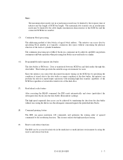
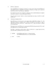
... immediately after the power supply to the IDD has been switched on the front panel of command, refer to SCSI Logical Interface Specifications. 2. For details of the disk drive. The meaning of the IDD. The external LED is possible to the IDD has been switched on the front of indication can be ...connected to set up the SCSI ID by short circuiting CN1-A3 and CN1-A4, and CN1-A5 and CN1-A6.) ...
... immediately after the power supply to the IDD has been switched on the front panel of command, refer to SCSI Logical Interface Specifications. 2. For details of the disk drive. The meaning of the IDD. The external LED is possible to the IDD has been switched on the front of indication can be ...connected to set up the SCSI ID by short circuiting CN1-A3 and CN1-A4, and CN1-A5 and CN1-A6.) ...

Manual/User Guide
Page 82
...with the START/STOP UNIT command. When this setup terminal is open, the IDD automatically identifies the DIFFSNS signal level on the SCSI bus and the IDD SCSI interface operation mode is enabled. Table 5.4 Write protect setting (MP model only) Write protect Write operation is set to the ... of the spindle motor Starting of the START/STOP UNIT command. (3) Write protect When the write protect function is enabled, writing to the disk medium is downloaded. This setting only determines the operation mode when the power supply is turned on or the microcode is downloaded. *1 Setting at...
...with the START/STOP UNIT command. When this setup terminal is open, the IDD automatically identifies the DIFFSNS signal level on the SCSI bus and the IDD SCSI interface operation mode is enabled. Table 5.4 Write protect setting (MP model only) Write protect Write operation is set to the ... of the spindle motor Starting of the START/STOP UNIT command. (3) Write protect When the write protect function is enabled, writing to the disk medium is downloaded. This setting only determines the operation mode when the power supply is turned on or the microcode is downloaded. *1 Setting at...


