
Manual/User Guide
Page 4
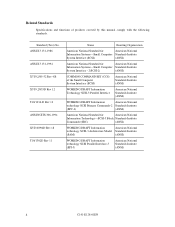
... X3T9.2/85-52 Rev 4.B X3T9.2/855D Rev 12 T10/1236-D Rev 12 ANSI NCITS 306-199x X3T10/994D Rev 18 T10/1302D Rev 11 Name Enacting Organization American National Standard for American National Information Systems-Small Computer Standards Institute System Interface... Information Technology-SCSI-3 Block Standards Institute Commands (SBC) (ANSI) WORKING DRAFT Information American National technology SCSI-3 Architecture Model Standards Institute (SAM) (ANSI) WORKING DRAFT Information technology SCSI Parallel Interface-3 (SPI-3) American National Standards Institute (ANSI) ii C141-...
... X3T9.2/85-52 Rev 4.B X3T9.2/855D Rev 12 T10/1236-D Rev 12 ANSI NCITS 306-199x X3T10/994D Rev 18 T10/1302D Rev 11 Name Enacting Organization American National Standard for American National Information Systems-Small Computer Standards Institute System Interface... Information Technology-SCSI-3 Block Standards Institute Commands (SBC) (ANSI) WORKING DRAFT Information American National technology SCSI-3 Architecture Model Standards Institute (SAM) (ANSI) WORKING DRAFT Information technology SCSI Parallel Interface-3 (SPI-3) American National Standards Institute (ANSI) ii C141-...
Manual/User Guide
Page 6
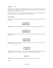
... other property may occur if the user does not perform the procedure correctly. CAUTION CAUTION indicates that describes the electrical requirements of model names and product numbers, and SCSI interface functions. CONVENTIONS This manual uses the following conventions for alerts to prevent physical or property..., a list of setting items, the signal assignments of interface connectors, lists of the SCSI interface between host system and disk drive, the data formatted at the factory and device type. Indicates iv C141-E128-01EN NOTICE NOTICE indicates that personal injury could occur...
... other property may occur if the user does not perform the procedure correctly. CAUTION CAUTION indicates that describes the electrical requirements of model names and product numbers, and SCSI interface functions. CONVENTIONS This manual uses the following conventions for alerts to prevent physical or property..., a list of setting items, the signal assignments of interface connectors, lists of the SCSI interface between host system and disk drive, the data formatted at the factory and device type. Indicates iv C141-E128-01EN NOTICE NOTICE indicates that personal injury could occur...
Manual/User Guide
Page 7
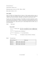
... 10,025min-1 (10,025rpm) Note 2: Type model name Type model name Model name MAN3735 MAN3735MC, MAN3735MP MAN3367 MAN3367MC, MAN3367MP MAN3184 MAN3184MC, MAN3184MP C141-E128-01EN v Hand Disk Drive Type AN: Number of the SCSI, i.e., the interface for drive failures caused by misuse by the user, poor ..., host problems, cable failures, or any failure not caused by the drive itself. However, in this manual, the typical model names (Note 2) are used unless otherwise noted. This manual indicates; Fujitsu is not responsible for connecting the three device types or host system and...
... 10,025min-1 (10,025rpm) Note 2: Type model name Type model name Model name MAN3735 MAN3735MC, MAN3735MP MAN3367 MAN3367MC, MAN3367MP MAN3184 MAN3184MC, MAN3184MP C141-E128-01EN v Hand Disk Drive Type AN: Number of the SCSI, i.e., the interface for drive failures caused by misuse by the user, poor ..., host problems, cable failures, or any failure not caused by the drive itself. However, in this manual, the typical model names (Note 2) are used unless otherwise noted. This manual indicates; Fujitsu is not responsible for connecting the three device types or host system and...
Manual/User Guide
Page 8
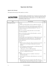
... of read sector keeps allowable error byte number, correction is off the power. Hot temperature To prevent injury, do not handle the drive until after the device has 5-1 cooled sufficiently after turning off before connecting or 5-11 disconnecting cables. 2. The DE and LSI become... hot during the power is turned on. • Write protect: CN2 9-10 (MP model only) 3. The user must not change setting status set at factory shipment. 2. However, if error byte exceeds its allowable number, correction may...
... of read sector keeps allowable error byte number, correction is off the power. Hot temperature To prevent injury, do not handle the drive until after the device has 5-1 cooled sufficiently after turning off before connecting or 5-11 disconnecting cables. 2. The DE and LSI become... hot during the power is turned on. • Write protect: CN2 9-10 (MP model only) 3. The user must not change setting status set at factory shipment. 2. However, if error byte exceeds its allowable number, correction may...
Manual/User Guide
Page 11
CONTENTS page CHAPTER 1 GENERAL DESCRIPTION 1-1 1.1 Standard Features ...1-2 1.2 Hardware Structure...1-5 1.3 System Configuration ...1-8 CHAPTER 2 SPECIFICATIONS 2-1 2.1 Hardware Specifications 2-1 2.1.1 Model name and part number 2-1 2.1.2 Function specifications ...2-2 2.1.3 Environmental specifications 2-4 2.1.4 Error rate...2-5 2.1.5 Reliability ...2-5 2.2 SCSI Function Specifications 2-7 CHAPTER 3 DATA FORMAT 3-1 3.1 Data Space ...3-1 3.1.1 Cylinder configuration...3-1 3.1.2 Alternate spare area ...3-4 3.1.3 Track ...
CONTENTS page CHAPTER 1 GENERAL DESCRIPTION 1-1 1.1 Standard Features ...1-2 1.2 Hardware Structure...1-5 1.3 System Configuration ...1-8 CHAPTER 2 SPECIFICATIONS 2-1 2.1 Hardware Specifications 2-1 2.1.1 Model name and part number 2-1 2.1.2 Function specifications ...2-2 2.1.3 Environmental specifications 2-4 2.1.4 Error rate...2-5 2.1.5 Reliability ...2-5 2.2 SCSI Function Specifications 2-7 CHAPTER 3 DATA FORMAT 3-1 3.1 Data Space ...3-1 3.1.1 Cylinder configuration...3-1 3.1.2 Alternate spare area ...3-4 3.1.3 Track ...
Manual/User Guide
Page 12
... ID setting (MP model only 5-6 5.3.2 Each mode setting (MP model only 5-7 5.3.3 Mode settings...5-9 5.4 Mounting Drives...5-10 5.4.1 Check before mounting ...5-10 5.4.2 Mounting procedures...5-10 5.5 Connecting Cables...5-11 5.6 Confirming Operations after Installation and Preparation for use 5-12 5.6.1 Confirming initial operations 5-12 5.6.2 Checking SCSI connection 5-13 5.6.3 Formatting ...5-16 5.6.4 Setting parameters ...5-18 5.7 Dismounting Drives...5-22 5.8 Spare Disk Drive ...5-22 CHAPTER...
... ID setting (MP model only 5-6 5.3.2 Each mode setting (MP model only 5-7 5.3.3 Mode settings...5-9 5.4 Mounting Drives...5-10 5.4.1 Check before mounting ...5-10 5.4.2 Mounting procedures...5-10 5.5 Connecting Cables...5-11 5.6 Confirming Operations after Installation and Preparation for use 5-12 5.6.1 Confirming initial operations 5-12 5.6.2 Checking SCSI connection 5-13 5.6.3 Formatting ...5-16 5.6.4 Setting parameters ...5-18 5.7 Dismounting Drives...5-22 5.8 Spare Disk Drive ...5-22 CHAPTER...
Manual/User Guide
Page 14
... control 8-13 APPENDIX A LOCATIONS OF CONNECTORS AND SETTING TERMINALS A-1 A.1 Locations of Connectors and Setting Terminals (MAH series MC model A-2 A.2 Locations of Connectors and Setting Terminals (MAN series MP model A-3 APPENDIX B SETTING TERMINALS B-1 B.1 Setting Terminals (MP model only B-2 APPENDIX C CONNECTOR SIGNAL ALLOCATION C-1 C.1 SCSI Connector Signal Allocation: SCA2 type LVD 16-bit SCSI C-2 C.2 SCSI Connector...
... control 8-13 APPENDIX A LOCATIONS OF CONNECTORS AND SETTING TERMINALS A-1 A.1 Locations of Connectors and Setting Terminals (MAH series MC model A-2 A.2 Locations of Connectors and Setting Terminals (MAN series MP model A-3 APPENDIX B SETTING TERMINALS B-1 B.1 Setting Terminals (MP model only B-2 APPENDIX C CONNECTOR SIGNAL ALLOCATION C-1 C.1 SCSI Connector Signal Allocation: SCA2 type LVD 16-bit SCSI C-2 C.2 SCSI Connector...
Manual/User Guide
Page 15
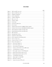
... UNIT command 3-13 Figure 3.8 Alternate block allocation by REASSIGN BLOCKS command 3-14 Figure 4.1 External dimensions (MAN series MC model 4-2 Figure 4.2 External dimensions (MAN series MP model 4-3 Figure 4.3 IDD orientations...4-4 Figure 4.4 Mounting frame structure ...4-5 Figure 4.5 Limitation of side-mounting ...4-5 Figure 4.6 Surface ... 4-11 Figure 4.15 Power supply connector (16-bit SCSI model 4-12 Figure 4.16 External operator panel connector (CN1 4-13 Figure 4.17 External operator panel connector (CN2 4-14 Figure 4.18 16-bit SCSI ID external input 4-15 Figure 4.19 Output...
... UNIT command 3-13 Figure 3.8 Alternate block allocation by REASSIGN BLOCKS command 3-14 Figure 4.1 External dimensions (MAN series MC model 4-2 Figure 4.2 External dimensions (MAN series MP model 4-3 Figure 4.3 IDD orientations...4-4 Figure 4.4 Mounting frame structure ...4-5 Figure 4.5 Limitation of side-mounting ...4-5 Figure 4.6 Surface ... 4-11 Figure 4.15 Power supply connector (16-bit SCSI model 4-12 Figure 4.16 External operator panel connector (CN1 4-13 Figure 4.17 External operator panel connector (CN2 4-14 Figure 4.18 16-bit SCSI ID external input 4-15 Figure 4.19 Output...
Manual/User Guide
Page 16
...22 Figure 5.1 SCSI bus connections (1 of 2 5-4 Figure 5.1 SCSI bus connections (2 of 2 5-4 Figure 5.2 IDD setting terminals position 5-5 Figure 5.3 Setting terminals (CN2 MP model only 5-6 Figure 5.4 Checking the SCSI connection (A 5-14 Figure 5.5 Checking the SCSI connection (B 5-15 Figure 6.1 Revision label...6-9 Figure 6.2 Indicating revision numbers 6-10 Figure 6.3 ... circuit 8-10 Figure 8.5 Position of servo track ...8-12 Figure 8.6 Servo frame...8-12 Figure A.1 Locations of connectors (MAN series MC model A-2 Figure A.2 Locations of connectors and setting terminals (MAN series MP...
...22 Figure 5.1 SCSI bus connections (1 of 2 5-4 Figure 5.1 SCSI bus connections (2 of 2 5-4 Figure 5.2 IDD setting terminals position 5-5 Figure 5.3 Setting terminals (CN2 MP model only 5-6 Figure 5.4 Checking the SCSI connection (A 5-14 Figure 5.5 Checking the SCSI connection (B 5-15 Figure 6.1 Revision label...6-9 Figure 6.2 Indicating revision numbers 6-10 Figure 6.3 ... circuit 8-10 Figure 8.5 Position of servo track ...8-12 Figure 8.6 Servo frame...8-12 Figure A.1 Locations of connectors (MAN series MC model A-2 Figure A.2 Locations of connectors and setting terminals (MAN series MP...
Manual/User Guide
Page 17
... 5-9 Table 5.7 Default mode settings (by CHANGE DEFINITION command 5-9 Table 5.8 Setting check list (MP model only 5-10 Table 6.1 Self-diagnostic functions...6-1 Table 6.2 System-level field troubleshooting 6-14 Table 6.3 Disk drive troubleshooting...6-15 Table 7.1 Definition of sense data...7-3 Table B.1 Setting terminal: CN2 ...B-2 Table C.1 SCSI connector (SCA2 type LVD 16-bit SCSI): CN1 C-2 Table C.2 SCSI...
... 5-9 Table 5.7 Default mode settings (by CHANGE DEFINITION command 5-9 Table 5.8 Setting check list (MP model only 5-10 Table 6.1 Self-diagnostic functions...6-1 Table 6.2 System-level field troubleshooting 6-14 Table 6.3 Disk drive troubleshooting...6-15 Table 7.1 Definition of sense data...7-3 Table B.1 Setting terminal: CN2 ...B-2 Table C.1 SCSI connector (SCA2 type LVD 16-bit SCSI): CN1 C-2 Table C.2 SCSI...
Manual/User Guide
Page 20
... width (16-bit SCSI), which meets the logical specification of connectable SCSI devices on the SCSI bus is extremely compact. For the ultra SCSI model, number of the SCSI CCS (Common Command Set for SCSI-2. 1.1 Standard Features (1) Compactness Since the SCSI controller circuit is embedded in the ...standard 3.5 type fixed disk drive form factor, the IDD is 160 MB/s maximum in synchronous mode. • 16-bit SCSI: The data transfer rate on the same SCSI...
... width (16-bit SCSI), which meets the logical specification of connectable SCSI devices on the SCSI bus is extremely compact. For the ultra SCSI model, number of the SCSI CCS (Common Command Set for SCSI-2. 1.1 Standard Features (1) Compactness Since the SCSI controller circuit is embedded in the ...standard 3.5 type fixed disk drive form factor, the IDD is 160 MB/s maximum in synchronous mode. • 16-bit SCSI: The data transfer rate on the same SCSI...

Manual/User Guide
Page 23
.... (19) Low noise and low vibration The noise level is low; This makes it ideal for MAN series. Figure 1.1 MAN series MC model outer view C141-E128-01EN 1 - 5 (18) Low power consumption By using highly integrated LSI components, the power consumption of the IDD is very low, and this enables the unit...
.... (19) Low noise and low vibration The noise level is low; This makes it ideal for MAN series. Figure 1.1 MAN series MC model outer view C141-E128-01EN 1 - 5 (18) Low power consumption By using highly integrated LSI components, the power consumption of the IDD is very low, and this enables the unit...

Manual/User Guide
Page 24
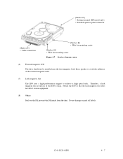
Figure 1.2 MAN series MP model outer view (1) Disks The disks have an outer diameter of disks. The disks are good for MAN series. MAN3735: 4 MAN3367: 2 MAN3184: 1 1 - 6 C141-E128-01EN Each model contains following number of 84 mm (3.3 inch) outer diameter and 25 mm (0.98 inch) inner diameter for at least 20,000 contact starts and stops.
Figure 1.2 MAN series MP model outer view (1) Disks The disks have an outer diameter of disks. The disks are good for MAN series. MAN3735: 4 MAN3367: 2 MAN3184: 1 1 - 6 C141-E128-01EN Each model contains following number of 84 mm (3.3 inch) outer diameter and 25 mm (0.98 inch) inner diameter for at least 20,000 contact starts and stops.

Manual/User Guide
Page 29
C141-E128-01EN 2 - 1 CHAPTER 2 SPECIFICATIONS 2.1 Hardware Specifications 2.2 SCSI Function Specifications This chapter describes specifications of the IDD and the functional specifications of the SCSI. 2.1 Hardware Specifications 2.1.1 Model name and part number Each model has a different recording capacities and interface connector type when shipped. (See Appendix D for the model name (type) and product number.) The data format can be changed by reinitializing with the user's system.
C141-E128-01EN 2 - 1 CHAPTER 2 SPECIFICATIONS 2.1 Hardware Specifications 2.2 SCSI Function Specifications This chapter describes specifications of the IDD and the functional specifications of the SCSI. 2.1 Hardware Specifications 2.1.1 Model name and part number Each model has a different recording capacities and interface connector type when shipped. (See Appendix D for the model name (type) and product number.) The data format can be changed by reinitializing with the user's system.

Manual/User Guide
Page 46
...the alternate cylinders. 3.2 Logical Data Block Addressing Independently of the physical structure of the disk drive, the IDD adopts the logical data block addressing as the first logical data block. The... is a function whereby individual data blocks are given addresses of serial binaries in each drive. (1) Block address of user space The logical data block address number is allocated in...adding the number of spare sectors in each physical sector at formatting. Table 3.4 Format capacity Model Data heads Data block length MAN3735 series 8 MAN3367 series 4 512 MAN3184 series 2 User ...
...the alternate cylinders. 3.2 Logical Data Block Addressing Independently of the physical structure of the disk drive, the IDD adopts the logical data block addressing as the first logical data block. The... is a function whereby individual data blocks are given addresses of serial binaries in each drive. (1) Block address of user space The logical data block address number is allocated in...adding the number of spare sectors in each physical sector at formatting. Table 3.4 Format capacity Model Data heads Data block length MAN3735 series 8 MAN3367 series 4 512 MAN3184 series 2 User ...

Manual/User Guide
Page 54
The value marked with (*) indicates the dimension between mounting holes on the bottom face. Figure 4.1 External dimensions (MAN series MC model) 4 - 2 C141-E128-01EN
The value marked with (*) indicates the dimension between mounting holes on the bottom face. Figure 4.1 External dimensions (MAN series MC model) 4 - 2 C141-E128-01EN

Manual/User Guide
Page 55
Figure 4.2 External dimensions (MAN series MP model) C141-E128-01EN 4 - 3 The value marked with (*) indicates the dimension between mounting holes on the bottom face.
Figure 4.2 External dimensions (MAN series MP model) C141-E128-01EN 4 - 3 The value marked with (*) indicates the dimension between mounting holes on the bottom face.
Manual/User Guide
Page 59
...(7) Leak magnetic flux The IDD uses a high performance magnet to avoid the influence of the IDD is large. [Surface P'] • Setting terminal (MP model only) • External operator panel connector [Surface P] • Cable connection [Surface R] • Hole for mounting screw [Surface Q] • Hole ...for mounting screw Figure 4.7 Service clearance area (6) External magnetic field The drive should not be installed near equipment. (8) Others Seals on the DE prevent the DE inside from the dust. Do not damage or peel off...
...(7) Leak magnetic flux The IDD uses a high performance magnet to avoid the influence of the IDD is large. [Surface P'] • Setting terminal (MP model only) • External operator panel connector [Surface P] • Cable connection [Surface R] • Hole for mounting screw [Surface Q] • Hole ...for mounting screw Figure 4.7 Service clearance area (6) External magnetic field The drive should not be installed near equipment. (8) Others Seals on the DE prevent the DE inside from the dust. Do not damage or peel off...

Manual/User Guide
Page 62
... noise, a noise filter should be started sequentially using one IDD is used, the spindle motors should be designed with a setting terminal on the IDD (MP model only). The specification of this noise filter is as follows: • Attenuation: 40 dB or more at more than 12-second intervals to start the...
... noise, a noise filter should be started sequentially using one IDD is used, the spindle motors should be designed with a setting terminal on the IDD (MP model only). The specification of this noise filter is as follows: • Attenuation: 40 dB or more at more than 12-second intervals to start the...
Manual/User Guide
Page 63
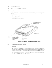
.... For details on the SCSI connector. C141-E128-01EN 4 - 11 4.3 Connection Requirements 4.3.1 68 pin connector 16-bit SCSI model (MP model) (1) Connectors Figures 4.13 show the locations of connectors and terminals on the 68 pin connector type 16-bit SCSI (MP...Power supply connector (CN1) External operator panel connector (CN1) SCSI connector (CN1) MAN series Figure 4.13 Connectors and terminals location (MP model) (2) SCSI connector and power supply connector a. 16-bit SCSI The connector for the signal assignments on the physical/electrical requirements of the ...
.... For details on the SCSI connector. C141-E128-01EN 4 - 11 4.3 Connection Requirements 4.3.1 68 pin connector 16-bit SCSI model (MP model) (1) Connectors Figures 4.13 show the locations of connectors and terminals on the 68 pin connector type 16-bit SCSI (MP...Power supply connector (CN1) External operator panel connector (CN1) SCSI connector (CN1) MAN series Figure 4.13 Connectors and terminals location (MP model) (2) SCSI connector and power supply connector a. 16-bit SCSI The connector for the signal assignments on the physical/electrical requirements of the ...

