
Product Manual
Page 4
... T10/1236-D Rev 19 ANSI NCITS. 306-1998 ANSI X3.270-1996 ANSI NCITS. 336-2000 Name Small Computer System Interface 2(SCSI-2) SCSI Primary Commands-2 (SPC-2) SCSI-3 Block Commands (SBC) SCSI-3 Architecture Model (SAM) SCSI Parallel Interface-3 (SPI-3) Enacting Organization American National Standards Institute (ANSI) American National Standards Institute (ANSI) American National Standards Institute (ANSI) American...
... T10/1236-D Rev 19 ANSI NCITS. 306-1998 ANSI X3.270-1996 ANSI NCITS. 336-2000 Name Small Computer System Interface 2(SCSI-2) SCSI Primary Commands-2 (SPC-2) SCSI-3 Block Commands (SBC) SCSI-3 Architecture Model (SAM) SCSI Parallel Interface-3 (SPI-3) Enacting Organization American National Standards Institute (ANSI) American National Standards Institute (ANSI) American National Standards Institute (ANSI) American...

Product Manual
Page 6
...to prevent physical or property damages to users or by standards. NOTICE NOTICE indicates that describes the electrical requirements of model names and product numbers, and SCSI interface functions. APPENDIX A to D The appendixes give supplementary information, including the locations of mounting setting terminals and... connectors, a list of setting items, the signal assignments of interface connectors, lists of the SCSI interface between host system and disk drive, the data formatted at the factory and device type. DANGER DANGER indicates that personal injury could occur if...
...to prevent physical or property damages to users or by standards. NOTICE NOTICE indicates that describes the electrical requirements of model names and product numbers, and SCSI interface functions. APPENDIX A to D The appendixes give supplementary information, including the locations of mounting setting terminals and... connectors, a list of setting items, the signal assignments of interface connectors, lists of the SCSI interface between host system and disk drive, the data formatted at the factory and device type. DANGER DANGER indicates that personal injury could occur if...

Product Manual
Page 7
...: LVD, 16-bit SCSI SCA2 connector 160MHz transfer MP: LVD, 16-bit SCSI 68 pin connector 160MHz transfer Formatted capacity (100 MB units) Disk drive size 3: 3.5 type. This manual indicates; However, in this manual, the typical model names (Note 2) are used unless otherwise noted. Hard Disk Drive Type AM: Number of the SCSI, i.e., the interface for drive failures caused by...
...: LVD, 16-bit SCSI SCA2 connector 160MHz transfer MP: LVD, 16-bit SCSI 68 pin connector 160MHz transfer Formatted capacity (100 MB units) Disk drive size 3: 3.5 type. This manual indicates; However, in this manual, the typical model names (Note 2) are used unless otherwise noted. Hard Disk Drive Type AM: Number of the SCSI, i.e., the interface for drive failures caused by...

Product Manual
Page 8
...not perform the procedure correctly. Hot temperature To prevent injury, do not handle the drive until after the device has cooled sufficiently after turning off the power. The DE ... 5-11 5-11 vi C141-E134-01EN Do not change the setting of terminals except following setting pins during operation and remain hot immediately after turning off before connecting or disconnecting cables. 2. Damage 1.... on. • Write protect: CN2 9-10 (MP model only) 3. With the system in which terminating resistor power is supplied via the SCSI cable, if the power is performed. The sector-data...
...not perform the procedure correctly. Hot temperature To prevent injury, do not handle the drive until after the device has cooled sufficiently after turning off the power. The DE ... 5-11 5-11 vi C141-E134-01EN Do not change the setting of terminals except following setting pins during operation and remain hot immediately after turning off before connecting or disconnecting cables. 2. Damage 1.... on. • Write protect: CN2 9-10 (MP model only) 3. With the system in which terminating resistor power is supplied via the SCSI cable, if the power is performed. The sector-data...

Product Manual
Page 11
... 1.2 Hardware Structure...1-5 1.3 System Configuration ...1-8 CHAPTER 2 SPECIFICATIONS ...2-1 2.1 Hardware Specifications ...2-1 2.1.1 Model name and part number ...2-1 2.1.2 Function specifications ...2-2 2.1.3 Environmental specifications...2-4 2.1.4 Error rate...2-5 2.1.5 Reliability ...2-5 2.2 SCSI Function Specifications ...2-7 CHAPTER 3 DATA FORMAT...3-1 3.1 Data Space ...3-1 3.1.1 Cylinder configuration ...3-1 3.1.2... Notes on mounting...4-4 4.2 Power Supply Requirements...4-8 4.3 Connection Requirements...4-11 4.3.1 68 pin connector 16-bit SCSI model (MP model 4-11 C141-E134-01EN ix
... 1.2 Hardware Structure...1-5 1.3 System Configuration ...1-8 CHAPTER 2 SPECIFICATIONS ...2-1 2.1 Hardware Specifications ...2-1 2.1.1 Model name and part number ...2-1 2.1.2 Function specifications ...2-2 2.1.3 Environmental specifications...2-4 2.1.4 Error rate...2-5 2.1.5 Reliability ...2-5 2.2 SCSI Function Specifications ...2-7 CHAPTER 3 DATA FORMAT...3-1 3.1 Data Space ...3-1 3.1.1 Cylinder configuration ...3-1 3.1.2... Notes on mounting...4-4 4.2 Power Supply Requirements...4-8 4.3 Connection Requirements...4-11 4.3.1 68 pin connector 16-bit SCSI model (MP model 4-11 C141-E134-01EN ix

Product Manual
Page 12
4.3.2 4.3.3 4.3.4 SCA2 type SCSI model (MC model 4-19 Cable connector requirements...4-20 External operator panel (MP model 4-22 CHAPTER 5 INSTALLATION ...5-1 5.1 Notes on Handling Drives...5-1 5.2 Connections ...5-3 5.3 Setting Terminals...5-5 5.3.1 SCSI ID setting (MP model only 5-6 5.3.2 Each mode setting (MP model only 5-7 5.3.3 Mode settings...5-9 5.4 Mounting Drives...5-10 5.4.1 Check before mounting...5-10 5.4.2 Mounting procedures ...5-10 5.5 Connecting Cables ...5-11 5.6 Confirming Operations after Installation and Preparation for use...
4.3.2 4.3.3 4.3.4 SCA2 type SCSI model (MC model 4-19 Cable connector requirements...4-20 External operator panel (MP model 4-22 CHAPTER 5 INSTALLATION ...5-1 5.1 Notes on Handling Drives...5-1 5.2 Connections ...5-3 5.3 Setting Terminals...5-5 5.3.1 SCSI ID setting (MP model only 5-6 5.3.2 Each mode setting (MP model only 5-7 5.3.3 Mode settings...5-9 5.4 Mounting Drives...5-10 5.4.1 Check before mounting...5-10 5.4.2 Mounting procedures ...5-10 5.5 Connecting Cables ...5-11 5.6 Confirming Operations after Installation and Preparation for use...
Product Manual
Page 14
... SETTING TERMINALS A-1 A.1 Locations of Connector (MC model A-2 A.2 Locations of Connectors and Setting Terminals (MP model A-3 APPENDIX B SETTING TERMINALS B-1 B.1 Setting Terminals (MP model)...B-2 APPENDIX C CONNECTOR SIGNAL ALLOCATION C-1 C.1 SCSI Connector Signal Allocation: SCA2 type LVD 16-bit SCSI C-2 C.2 SCSI Connector Signal Allocation: 68 pin type LVD 16-bit SCSI C-3 APPENDIX D MODEL NAMES AND PRODUCT NUMBERS D-1 D.1 Model Names and Product Numbers D-2 INDEX ...IN-1 xii...
... SETTING TERMINALS A-1 A.1 Locations of Connector (MC model A-2 A.2 Locations of Connectors and Setting Terminals (MP model A-3 APPENDIX B SETTING TERMINALS B-1 B.1 Setting Terminals (MP model)...B-2 APPENDIX C CONNECTOR SIGNAL ALLOCATION C-1 C.1 SCSI Connector Signal Allocation: SCA2 type LVD 16-bit SCSI C-2 C.2 SCSI Connector Signal Allocation: 68 pin type LVD 16-bit SCSI C-3 APPENDIX D MODEL NAMES AND PRODUCT NUMBERS D-1 D.1 Model Names and Product Numbers D-2 INDEX ...IN-1 xii...

Product Manual
Page 15
... allocation by FORMAT UNIT command 3-13 Alternate block allocation by REASSIGN BLOCKS command 3-14 External dimensions (MC model 4-2 External dimensions (MP model 4-3 IDD orientations...4-4 Mounting frame structure...4-5 Limitation of side-mounting 4-5 Surface temperature measurement points 4-6 Service clearance...off sequence (3)...4-9 AC noise filter (recommended 4-10 Connectors and terminals location (MP model 4-11 16-bit SCSI interface connector 4-12 Power supply connector (16-bit SCSI model 4-12 External operator panel connector (CN1 4-13 External operator panel connector (CN2 4-...
... allocation by FORMAT UNIT command 3-13 Alternate block allocation by REASSIGN BLOCKS command 3-14 External dimensions (MC model 4-2 External dimensions (MP model 4-3 IDD orientations...4-4 Mounting frame structure...4-5 Limitation of side-mounting 4-5 Surface temperature measurement points 4-6 Service clearance...off sequence (3)...4-9 AC noise filter (recommended 4-10 Connectors and terminals location (MP model 4-11 16-bit SCSI interface connector 4-12 Power supply connector (16-bit SCSI model 4-12 External operator panel connector (CN1 4-13 External operator panel connector (CN2 4-...
Product Manual
Page 16
... 8.4 Figure 8.5 Figure 8.6 Figure A.1 Figure A.2 Connectors location of MC model 4-19 SCA2 type SCSI connector 4-20 External operator panel circuit example 4-22 SCSI bus connections (1 of 2 5-4 SCSI bus connections (2 of 2 5-4 IDD setting terminals position (MP model only 5-5 Setting terminator (CN2 on MP model only 5-6 Checking the SCSI connection (A 5-14 Checking the SCSI connection (B 5-15 Revision label...6-9 Indicating revision numbers 6-10...
... 8.4 Figure 8.5 Figure 8.6 Figure A.1 Figure A.2 Connectors location of MC model 4-19 SCA2 type SCSI connector 4-20 External operator panel circuit example 4-22 SCSI bus connections (1 of 2 5-4 SCSI bus connections (2 of 2 5-4 IDD setting terminals position (MP model only 5-5 Setting terminator (CN2 on MP model only 5-6 Checking the SCSI connection (A 5-14 Checking the SCSI connection (B 5-15 Revision label...6-9 Indicating revision numbers 6-10...
Product Manual
Page 17
... CHANGE DEFINITION command 5-9 Setting check list (MP model only 5-10 Self-diagnostic functions...6-1 System-level field troubleshooting 6-14 Disk drive troubleshooting 6-15 Definition of sense data...7-3 Setting terminal: CN2 (MP model B-2 SCSI connector (SCA2 type LVD 16-bit SCSI): CN1 C-2 SCSI connector (68 pin type LVD 16-bit SCSI): CN1 C-3 MAN series model names and product numbers D-2 C141-E134-01EN...
... CHANGE DEFINITION command 5-9 Setting check list (MP model only 5-10 Self-diagnostic functions...6-1 System-level field troubleshooting 6-14 Disk drive troubleshooting 6-15 Definition of sense data...7-3 Setting terminal: CN2 (MP model B-2 SCSI connector (SCA2 type LVD 16-bit SCSI): CN1 C-2 SCSI connector (68 pin type LVD 16-bit SCSI): CN1 C-3 MAN series model names and product numbers D-2 C141-E134-01EN...

Product Manual
Page 20
... in synchronous mode. 1 - 2 C141-E134-01EN For the ultra SCSI model, number of connectable SCSI devices on the same SCSI bus is varied as follows. • 8-bit SCSI: 8 drives max. • 16-bit SCSI: 16 drives max. (4) High speed data transfer Such a high data transfer rate on the SCSI bus can be connected directly to accommodate future expansion of...
... in synchronous mode. 1 - 2 C141-E134-01EN For the ultra SCSI model, number of connectable SCSI devices on the same SCSI bus is varied as follows. • 8-bit SCSI: 8 drives max. • 16-bit SCSI: 16 drives max. (4) High speed data transfer Such a high data transfer rate on the SCSI bus can be connected directly to accommodate future expansion of...

Product Manual
Page 23
... vibration The noise level is low; This makes it ideal for office use. (20) Microcode downloading The IDD implements the microcode download feature. Figure 1.1 MC model outer view C141-E134-01EN 1 - 5 (18) Low power consumption By using highly integrated LSI components, the power consumption of the IDD is very low, and...
... vibration The noise level is low; This makes it ideal for office use. (20) Microcode downloading The IDD implements the microcode download feature. Figure 1.1 MC model outer view C141-E134-01EN 1 - 5 (18) Low power consumption By using highly integrated LSI components, the power consumption of the IDD is very low, and...

Product Manual
Page 24
Each model contains following number of 70 mm (2.8 inch) outer diameter and 25 mm (0.98 inch) inner diameter for at least 20,000 contact starts and stops. Figure 1.2 MP model outer view (1) Disks The disks have an outer diameter of disks. The disks are good for MAM series. MAM3367: 4 MAM3184: 2 1 - 6 C141-E134-01EN
Each model contains following number of 70 mm (2.8 inch) outer diameter and 25 mm (0.98 inch) inner diameter for at least 20,000 contact starts and stops. Figure 1.2 MP model outer view (1) Disks The disks have an outer diameter of disks. The disks are good for MAM series. MAM3367: 4 MAM3184: 2 1 - 6 C141-E134-01EN

Product Manual
Page 29
CHAPTER 2 SPECIFICATIONS 2.1 Hardware Specifications 2.2 SCSI Function Specifications This chapter describes specifications of the IDD and the functional specifications of the SCSI. 2.1 Hardware Specifications 2.1.1 Model name and part number Each model has a different recording capacities and interface connector type when shipped. (See Appendix D for the model name (type) and product number.) The data format can be changed by reinitializing with the user's system. C141-E134-01EN 2 - 1
CHAPTER 2 SPECIFICATIONS 2.1 Hardware Specifications 2.2 SCSI Function Specifications This chapter describes specifications of the IDD and the functional specifications of the SCSI. 2.1 Hardware Specifications 2.1.1 Model name and part number Each model has a different recording capacities and interface connector type when shipped. (See Appendix D for the model name (type) and product number.) The data format can be changed by reinitializing with the user's system. C141-E134-01EN 2 - 1

Product Manual
Page 35
... the PCA × TERMPWR signal send function Ο Connector 68 pin P cable connector 80 pin SCA2 connector Ο (MP model) Ο (MC model) Data bus parity (Data bus CRC) Ο Bus arbitration function Ο Disconnection/reconnection function Ο Addressing SCSI ID 16-bit SCSI LUN (logical unit number) 8-bit SCSI (Single-Ended type) Data transfer (LVD type) (Synchronous 16...
... the PCA × TERMPWR signal send function Ο Connector 68 pin P cable connector 80 pin SCA2 connector Ο (MP model) Ο (MC model) Data bus parity (Data bus CRC) Ο Bus arbitration function Ο Disconnection/reconnection function Ο Addressing SCSI ID 16-bit SCSI LUN (logical unit number) 8-bit SCSI (Single-Ended type) Data transfer (LVD type) (Synchronous 16...

Product Manual
Page 46
... IDD treats sector 0, track 0, cylinder 0 as the first logical data block. Logical data blocks are given addresses of serial binaries in each drive. (1) Block address of user space The logical data block address number is consecutively assigned to the first data block. Data on the disk medium... assigned in the same way as step 1). 3) Subsequent logical data blocks are assigned to each physical sector at formatting. Table 3.4 Format capacity Model Data heads Data block length MAM3367 series 8 512 MAM3184 series 4 User blocks 71,770,616 35,885,344 Format capacity (GB) 36.74...
... IDD treats sector 0, track 0, cylinder 0 as the first logical data block. Logical data blocks are given addresses of serial binaries in each drive. (1) Block address of user space The logical data block address number is consecutively assigned to the first data block. Data on the disk medium... assigned in the same way as step 1). 3) Subsequent logical data blocks are assigned to each physical sector at formatting. Table 3.4 Format capacity Model Data heads Data block length MAM3367 series 8 512 MAM3184 series 4 User blocks 71,770,616 35,885,344 Format capacity (GB) 36.74...

Product Manual
Page 54
Figure 4.1 External dimensions (MC model) 4 - 2 C141-E134-01EN The value marked with (*) indicates the dimension between mounting holes on the bottom face.
Figure 4.1 External dimensions (MC model) 4 - 2 C141-E134-01EN The value marked with (*) indicates the dimension between mounting holes on the bottom face.

Product Manual
Page 55
The value marked with (*) indicates the dimension between mounting holes on the bottom face. Figure 4.2 External dimensions (MP model) C141-E134-01EN 4 - 3
The value marked with (*) indicates the dimension between mounting holes on the bottom face. Figure 4.2 External dimensions (MP model) C141-E134-01EN 4 - 3
Product Manual
Page 59
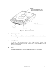
... Mount the IDD so that the leak magnetic flux does not affect to achieve a high speed seek. [Surface P'] • Setting terminal(MP model only) • External operator panel connector [Surface P] • Cable connection [Surface R] • Hole for mounting screw [Surface Q] •...; Hole for mounting screw Figure 4.7 Service clearance area (6) External magnetic field The drive should not be installed near the ferromagnetic body like a speaker to avoid the influence of the IDD is large. C141-E134-01EN 4 - 7 Therefore...
... Mount the IDD so that the leak magnetic flux does not affect to achieve a high speed seek. [Surface P'] • Setting terminal(MP model only) • External operator panel connector [Surface P] • Cable connection [Surface R] • Hole for mounting screw [Surface Q] •...; Hole for mounting screw Figure 4.7 Service clearance area (6) External magnetic field The drive should not be installed near the ferromagnetic body like a speaker to avoid the influence of the IDD is large. C141-E134-01EN 4 - 7 Therefore...

Product Manual
Page 62
... control mode, see Subsection 5.3.2. b) Turn on the IDD (MP model only). For details of the power supply unit. See Subsection 5.3.2 for the terminating resistor is supplied from the IDD to other SCSI devices through the SCSI bus, the current-carrying capacity of the +5 VDC power supply line...should be started sequentially using one IDD is selected with considering of an increase of supplying power to the terminating resistor, refer to SCSI Logical Interface Specifications. For how to 200 mA. For the electrical condition of up to set a spindle motor start the spindle motors...
... control mode, see Subsection 5.3.2. b) Turn on the IDD (MP model only). For details of the power supply unit. See Subsection 5.3.2 for the terminating resistor is supplied from the IDD to other SCSI devices through the SCSI bus, the current-carrying capacity of the +5 VDC power supply line...should be started sequentially using one IDD is selected with considering of an increase of supplying power to the terminating resistor, refer to SCSI Logical Interface Specifications. For how to 200 mA. For the electrical condition of up to set a spindle motor start the spindle motors...

