
Product Manual
Page 5
PREFACE This manual describes the MAM3367MC/MP, MAM3184MC/MP (hereafter, MAM series), 3.5 type fixed disk drives with an embedded SCSI controller. Chapter 1 GENERAL DESCRIPTION This chapter introduces the MAM series disk drives and discusses their installation environment. Chapter 4 INSTALLATION REQUIREMENTS This chapter describes the basic physical and electrical requirements for setting device number and operation modes, mounting the disk drive, connecting the cables, and confirming drive operation. Chapter 6 DIAGNOSIS and MAINTENANCE This chapter describes the...
PREFACE This manual describes the MAM3367MC/MP, MAM3184MC/MP (hereafter, MAM series), 3.5 type fixed disk drives with an embedded SCSI controller. Chapter 1 GENERAL DESCRIPTION This chapter introduces the MAM series disk drives and discusses their installation environment. Chapter 4 INSTALLATION REQUIREMENTS This chapter describes the basic physical and electrical requirements for setting device number and operation modes, mounting the disk drive, connecting the cables, and confirming drive operation. Chapter 6 DIAGNOSIS and MAINTENANCE This chapter describes the...

Product Manual
Page 7
..., repairs, or replacement. Hard Disk Drive Type AM: Number of the SCSI, i.e., the interface for drive failures caused by misuse by the user, poor environmental conditions, power trouble, host problems, cable failures, or any failure not caused by the drive itself. This manual indicates; These disk drives may be called intelligent disk drives (IDD), drives, or devices in this manual. Note 1: Model names M AM 3 367 MC Interface types MC: LVD, 16-bit SCSI SCA2 connector 160MHz transfer MP: LVD, 16-bit SCSI 68 pin connector 160MHz transfer Formatted capacity (100...
..., repairs, or replacement. Hard Disk Drive Type AM: Number of the SCSI, i.e., the interface for drive failures caused by misuse by the user, poor environmental conditions, power trouble, host problems, cable failures, or any failure not caused by the drive itself. This manual indicates; These disk drives may be called intelligent disk drives (IDD), drives, or devices in this manual. Note 1: Model names M AM 3 367 MC Interface types MC: LVD, 16-bit SCSI SCA2 connector 160MHz transfer MP: LVD, 16-bit SCSI 68 pin connector 160MHz transfer Formatted capacity (100...

Product Manual
Page 8
... supplied via the SCSI cable, if the power is shipped from the factory. However, if error byte exceeds its allowable number, correction may occur if the user does not perform the procedure correctly. Hot temperature To prevent injury, do not handle the drive until after the device has cooled sufficiently after turning off before connecting or disconnecting cables. 2. Do not change the setting of read sector keeps allowable error...
... supplied via the SCSI cable, if the power is shipped from the factory. However, if error byte exceeds its allowable number, correction may occur if the user does not perform the procedure correctly. Hot temperature To prevent injury, do not handle the drive until after the device has cooled sufficiently after turning off before connecting or disconnecting cables. 2. Do not change the setting of read sector keeps allowable error...
Product Manual
Page 14
... frame format ...8-12 Spindle motor control ...8-12 Voice coil motor control...8-13 APPENDIX A LOCATIONS OF CONNECTORS AND SETTING TERMINALS A-1 A.1 Locations of Connector (MC model A-2 A.2 Locations of Connectors and Setting Terminals (MP model A-3 APPENDIX B SETTING TERMINALS B-1 B.1 Setting Terminals (MP model)...B-2 APPENDIX C CONNECTOR SIGNAL ALLOCATION C-1 C.1 SCSI Connector Signal Allocation: SCA2 type LVD 16-bit SCSI C-2 C.2 SCSI Connector Signal Allocation: 68 pin type LVD 16-bit SCSI C-3 APPENDIX D MODEL NAMES AND PRODUCT NUMBERS D-1 D.1 Model Names and Product Numbers...
... frame format ...8-12 Spindle motor control ...8-12 Voice coil motor control...8-13 APPENDIX A LOCATIONS OF CONNECTORS AND SETTING TERMINALS A-1 A.1 Locations of Connector (MC model A-2 A.2 Locations of Connectors and Setting Terminals (MP model A-3 APPENDIX B SETTING TERMINALS B-1 B.1 Setting Terminals (MP model)...B-2 APPENDIX C CONNECTOR SIGNAL ALLOCATION C-1 C.1 SCSI Connector Signal Allocation: SCA2 type LVD 16-bit SCSI C-2 C.2 SCSI Connector Signal Allocation: 68 pin type LVD 16-bit SCSI C-3 APPENDIX D MODEL NAMES AND PRODUCT NUMBERS D-1 D.1 Model Names and Product Numbers...
Product Manual
Page 16
... of MC model 4-19 SCA2 type SCSI connector 4-20 External operator panel circuit example 4-22 SCSI bus connections (1 of 2 5-4 SCSI bus connections (2 of 2 5-4 IDD setting terminals position (MP model only 5-5 Setting terminator (CN2 on MP model only 5-6 Checking the SCSI connection (A 5-14 Checking the SCSI connection (B 5-15 Revision label...6-9 Indicating revision numbers 6-10 Test flowchart ...6-11 Format of extended sense data 7-2 Circuit configuration ...8-4 IDD operation sequence at power-on 8-5 Block diagram of read-write circuit 8-8 Block diagram of servo control circuit...
... of MC model 4-19 SCA2 type SCSI connector 4-20 External operator panel circuit example 4-22 SCSI bus connections (1 of 2 5-4 SCSI bus connections (2 of 2 5-4 IDD setting terminals position (MP model only 5-5 Setting terminator (CN2 on MP model only 5-6 Checking the SCSI connection (A 5-14 Checking the SCSI connection (B 5-15 Revision label...6-9 Indicating revision numbers 6-10 Test flowchart ...6-11 Format of extended sense data 7-2 Circuit configuration ...8-4 IDD operation sequence at power-on 8-5 Block diagram of read-write circuit 8-8 Block diagram of servo control circuit...

Product Manual
Page 30
... m max (*9) Data transfer rate (*10) Disk drive SCSI Synchronous mode 68.6 to 528 byte (Fixed length) ANSI X3.131-1994 conformity SCSI command specification SPC-2 (T10/1236-D Rev 19), SBC (ANSI NCITS.306-1998), SAM (ANSI × 3.270-1996), SPI-3 (ANSI NCITS. 336-2000) Data buffer 8 MB FIFO ring buffer Acostic noise (Ready) 3.9 bels 2 - 2 C141-E134-01EN Table 2.1 Function specifications Item Formatted capacity/device (*1) Number of disks Number of heads Number...
... m max (*9) Data transfer rate (*10) Disk drive SCSI Synchronous mode 68.6 to 528 byte (Fixed length) ANSI X3.131-1994 conformity SCSI command specification SPC-2 (T10/1236-D Rev 19), SBC (ANSI NCITS.306-1998), SAM (ANSI × 3.270-1996), SPI-3 (ANSI NCITS. 336-2000) Data buffer 8 MB FIFO ring buffer Acostic noise (Ready) 3.9 bels 2 - 2 C141-E134-01EN Table 2.1 Function specifications Item Formatted capacity/device (*1) Number of disks Number of heads Number...

Product Manual
Page 31
... power pin (SCSI connector) which supplies power to the response speed of initiator and by changing the logical block length and using spare sector space. See Chapter 3 for disks to completely stop from power on 1 connection case. (*9) 1 host, 15 devices case. (*10) The maximum data transfer rate may be restricted to other terminators is not used. C141-E134-01EN 2 - 3 The formatted capacity listed in the table is as follows: Read seek 1 Pos. Time: 0.29 ms Max...
... power pin (SCSI connector) which supplies power to the response speed of initiator and by changing the logical block length and using spare sector space. See Chapter 3 for disks to completely stop from power on 1 connection case. (*9) 1 host, 15 devices case. (*10) The maximum data transfer rate may be restricted to other terminators is not used. C141-E134-01EN 2 - 3 The formatted capacity listed in the table is as follows: Read seek 1 Pos. Time: 0.29 ms Max...

Product Manual
Page 33
... after installation Vibration displacement should be less than 100 mVp-p. 2.1.4 Error rate Errors detected during its life time is defined as: MTBF= Operating time (hours) at the connector. (*6) The terminator power pin (SCSI connector) which supplies power to be accessed should be distributed over the disk medium equally. (1) Unrecoverable error rate Errors which can be recovered within 63 retries and ECC correction should not exceed 1 per 108 seeks. 2.1.5 Reliability (1) Mean Time Between Failures (MTBF) MTBF...
... after installation Vibration displacement should be less than 100 mVp-p. 2.1.4 Error rate Errors detected during its life time is defined as: MTBF= Operating time (hours) at the connector. (*6) The terminator power pin (SCSI connector) which supplies power to be accessed should be distributed over the disk medium equally. (1) Unrecoverable error rate Errors which can be recovered within 63 retries and ECC correction should not exceed 1 per 108 seeks. 2.1.5 Reliability (1) Mean Time Between Failures (MTBF) MTBF...
Product Manual
Page 34
... IDD is operating. (4) Data security at power failure Integrity of the data on the disk is being performed. The above does not applied to 55°C • DE surface temperature: 56°C and more 5 years 4.5 years 4 years 3.5 years Strengthen cooling power so that requires repair, adjustments, or replacement. The drive is designed for a MTTR of 30 minutes or less. (3) Service life The service life under...
... IDD is operating. (4) Data security at power failure Integrity of the data on the disk is being performed. The above does not applied to 55°C • DE surface temperature: 56°C and more 5 years 4.5 years 4 years 3.5 years Strengthen cooling power so that requires repair, adjustments, or replacement. The drive is designed for a MTTR of 30 minutes or less. (3) Service life The service life under...
Product Manual
Page 59
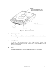
... • Setting terminal(MP model only) • External operator panel connector [Surface P] • Cable connection [Surface R] • Hole for mounting screw [Surface Q] • Hole for mounting screw Figure 4.7 Service clearance area (6) External magnetic field The drive should not be installed near equipment....external magnetic field. (7) Leak magnetic flux The IDD uses a high performance magnet to avoid the influence of the IDD is large. Mount the IDD so that the leak magnetic flux does not affect to near the ferromagnetic body like a speaker to achieve a high speed seek...
... • Setting terminal(MP model only) • External operator panel connector [Surface P] • Cable connection [Surface R] • Hole for mounting screw [Surface Q] • Hole for mounting screw Figure 4.7 Service clearance area (6) External magnetic field The drive should not be installed near equipment....external magnetic field. (7) Leak magnetic flux The IDD uses a high performance magnet to avoid the influence of the IDD is large. Mount the IDD so that the leak magnetic flux does not affect to near the ferromagnetic body like a speaker to achieve a high speed seek...
Product Manual
Page 75
... after turning off the power. CHAPTER 5 INSTALLATION 5.1 Notes on Handling Drives 5.2 Connections 5.3 Setting Terminals 5.4 Mounting Drives 5.5 Connecting Cables 5.6 Confirming Operations after Installation and Preparation for Use 5.7 Dismounting Drives 5.8 Spare Disk Drive This chapter describes the notes on handling drives, connections, setting switches and plugs, mounting drives, connecting cables, confirming drive operations after installation and preparation for setting. CAUTION Hot temperature To prevent injury, do not handle the drive until after the device has cooled sufficiently...
... after turning off the power. CHAPTER 5 INSTALLATION 5.1 Notes on Handling Drives 5.2 Connections 5.3 Setting Terminals 5.4 Mounting Drives 5.5 Connecting Cables 5.6 Confirming Operations after Installation and Preparation for Use 5.7 Dismounting Drives 5.8 Spare Disk Drive This chapter describes the notes on handling drives, connections, setting switches and plugs, mounting drives, connecting cables, confirming drive operations after installation and preparation for setting. CAUTION Hot temperature To prevent injury, do not handle the drive until after the device has cooled sufficiently...

Product Manual
Page 76
... keep removed screws and other parts where they are pins 9, 10 (Write Protect) in CN2. (MP model) b) Do not move the drive when power is not turned over. (5) Delivery a) When delivering the drive, provide packaging and do not turn it over. In this case, fully protect the PCAs and interface connector so that the "This Side Up" sign side is free from...
... keep removed screws and other parts where they are pins 9, 10 (Write Protect) in CN2. (MP model) b) Do not move the drive when power is not turned over. (5) Delivery a) When delivering the drive, provide packaging and do not turn it over. In this case, fully protect the PCAs and interface connector so that the "This Side Up" sign side is free from...
Product Manual
Page 90
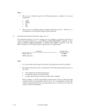
... data and retry recovery for each model (part number) when shipped from the default format, all sides of the terminals. The user can be obtained with the MODE SELECT or MODE SELECT EXTENDED command. Refer to Chapter 5 of logical data blocks after initialization is installed in the format parameter (page code = 3) and drive parameter (page code = 4). 5 - 16 C141-E134-01EN However, when the system needs data attributes different from the factory, the disk need not be formatted...
... data and retry recovery for each model (part number) when shipped from the default format, all sides of the terminals. The user can be obtained with the MODE SELECT or MODE SELECT EXTENDED command. Refer to Chapter 5 of logical data blocks after initialization is installed in the format parameter (page code = 3) and drive parameter (page code = 4). 5 - 16 C141-E134-01EN However, when the system needs data attributes different from the factory, the disk need not be formatted...

Product Manual
Page 92
This enables the IDD to operate by using the parameter value set by setting the following parameters with the MODE SELECT or MODE SELECT EXTENDED command: • Error recovery parameter • Disconnection/reconnection parameter • Caching parameter • Control mode parameter With the MODE SELECT or MODE SELECT EXTENDED command, specify 1 for the "SP" bit on CDB to the saved parameter value if the saving operation is not executed at installation. 5 - 18 C141-E134-01EN Although the IDD operations are assured...
This enables the IDD to operate by using the parameter value set by setting the following parameters with the MODE SELECT or MODE SELECT EXTENDED command: • Error recovery parameter • Disconnection/reconnection parameter • Caching parameter • Control mode parameter With the MODE SELECT or MODE SELECT EXTENDED command, specify 1 for the "SP" bit on CDB to the saved parameter value if the saving operation is not executed at installation. 5 - 18 C141-E134-01EN Although the IDD operations are assured...
Product Manual
Page 94
... 2 of SCSI Logical Interface Specifications for how to transfer data on the SCSI bus at a read (READ or READ EXTENDED command) or write operation (WRITE, WRITE EXTENDED, or WRITE AND VERIFY command) of the specified values by measuring performance in normal operations. (2) Disconnection/reconnection parameters (page code = 2) The following parameters according to evaluate the validity of the disk. The user also can arbitrarily specify the following parameters are used to optimize the start timing of reconnection...
... 2 of SCSI Logical Interface Specifications for how to transfer data on the SCSI bus at a read (READ or READ EXTENDED command) or write operation (WRITE, WRITE EXTENDED, or WRITE AND VERIFY command) of the specified values by measuring performance in normal operations. (2) Disconnection/reconnection parameters (page code = 2) The following parameters according to evaluate the validity of the disk. The user also can arbitrarily specify the following parameters are used to optimize the start timing of reconnection...
Product Manual
Page 103
... model, part number (P/N), revision number, serial number (S/N), and date of manufacturing b) Error status • Date when the error occurred • System configuration • Environmental conditions (temperature, humidity, and voltage) c) Error history d) Error contents • Outline of inconvenience • Issued commands and specified parameters • Sense data • Other error analysis information CAUTION Data loss Save data stored on the disk drive before requesting repair. The DE cannot be replaced in the field. (4) Service system and repairs Fujitsu has the service...
... model, part number (P/N), revision number, serial number (S/N), and date of manufacturing b) Error status • Date when the error occurred • System configuration • Environmental conditions (temperature, humidity, and voltage) c) Error history d) Error contents • Outline of inconvenience • Issued commands and specified parameters • Sense data • Other error analysis information CAUTION Data loss Save data stored on the disk drive before requesting repair. The DE cannot be replaced in the field. (4) Service system and repairs Fujitsu has the service...

Product Manual
Page 110
... DC power cable AC and DC power level Electrical noise Interface cable connection Terminating resistors Drive selection address Plug setup System cables System diagnostic test Intermittent or nonfatal errors Recommended work Check that the power cable is correctly connected to 12.6 VDC. Check that the DC voltage is correctly connected between the disk drive and controller. Check that the +12 VDC supply (pins 1 and 2 of the power connector of the power connector) is 4.75 to the hardware and software manuals supplied...
... DC power cable AC and DC power level Electrical noise Interface cable connection Terminating resistors Drive selection address Plug setup System cables System diagnostic test Intermittent or nonfatal errors Recommended work Check that the power cable is correctly connected to 12.6 VDC. Check that the DC voltage is correctly connected between the disk drive and controller. Check that the +12 VDC supply (pins 1 and 2 of the power connector of the power connector) is 4.75 to the hardware and software manuals supplied...
Product Manual
Page 136
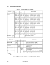
... - 24 Motor start mode Open Started by the START/STOP command Short Started by turning the power supply on (*) Force Narrow Open Width of 16 bit bus (*) Short Width of the setting requirements and notes. B.1 Setting Terminals (MP model) Table B.1 Setting terminal: CN2 (MP model) Setting item SCSI ID Write protect Pins 9 - 10 7 - 8 5 - 6 (Open) Open (Open) Open (Open) Open (Open) Open (Open) Short (Open) Short (Open) Short (Open) Short Short Open Short Open Short Open Short Open Short Short Short Short...
... - 24 Motor start mode Open Started by the START/STOP command Short Started by turning the power supply on (*) Force Narrow Open Width of 16 bit bus (*) Short Width of the setting requirements and notes. B.1 Setting Terminals (MP model) Table B.1 Setting terminal: CN2 (MP model) Setting item SCSI ID Write protect Pins 9 - 10 7 - 8 5 - 6 (Open) Open (Open) Open (Open) Open (Open) Open (Open) Short (Open) Short (Open) Short (Open) Short Short Open Short Open Short Open Short Open Short Short Short Short...

Product Manual
Page 144
... 5-1 H hardware function test 6-2 hardware specification 2-1 hardware structure 1-5 head 1-7, 8-2 head IC 8-7 head position correction 8-6 high speed data transfer 1-2 high speed positioning 1-4 I IDD operation sequence at power-on 8-5 IDD setting terminal position 5-5 indicating revision number 6-10 indicating revision number at factory shipment 6-9 initial seek operation check 6-12 initial self-diagnostics 6-2 input signal 4-17 installation 5-1 installation/removal/replacement 5-2 installation requirement 4-1 interface test 6-5 internal test space 3-4 L large capacity 1-4 leak magnetic flux...
... 5-1 H hardware function test 6-2 hardware specification 2-1 hardware structure 1-5 head 1-7, 8-2 head IC 8-7 head position correction 8-6 high speed data transfer 1-2 high speed positioning 1-4 I IDD operation sequence at power-on 8-5 IDD setting terminal position 5-5 indicating revision number 6-10 indicating revision number at factory shipment 6-9 initial seek operation check 6-12 initial self-diagnostics 6-2 input signal 4-17 installation 5-1 installation/removal/replacement 5-2 installation requirement 4-1 interface test 6-5 internal test space 3-4 L large capacity 1-4 leak magnetic flux...

Product Manual
Page 145
... code=7 5-19 parts replacement 6-8 parts that can be replaced in field 6-7 physical sector allocation 3-5 PLO Sync 3-8 positioning error rate 2-5 power cable 4-21 powering-on 5-12 power on/off sequence 4-8, 4-9 power-on sequence 8-5 power supply connector 4-11, 4-12 power supply requirement 4-8 power supply to SCSI terminating resistor 4-10 precaution 6-5 preventive maintenance 6-6 principle of operation 8-1 programmable data block length 1-4 programmable multi-segment data buffer 1-3 R random/sequential read test 6-5 read-ahead cache feature 1-3 read-write circuit 1-7, 8-3 read/write circuit...
... code=7 5-19 parts replacement 6-8 parts that can be replaced in field 6-7 physical sector allocation 3-5 PLO Sync 3-8 positioning error rate 2-5 power cable 4-21 powering-on 5-12 power on/off sequence 4-8, 4-9 power-on sequence 8-5 power supply connector 4-11, 4-12 power supply requirement 4-8 power supply to SCSI terminating resistor 4-10 precaution 6-5 preventive maintenance 6-6 principle of operation 8-1 programmable data block length 1-4 programmable multi-segment data buffer 1-3 R random/sequential read test 6-5 read-ahead cache feature 1-3 read-write circuit 1-7, 8-3 read/write circuit...


