

Product Manual
Page 6
...appendixes give supplementary information, including the locations of mounting setting terminals and connectors, a list of setting items, the signal assignments of interface connectors, lists of the SCSI interface between host system and disk drive, the data formatted at the factory and device type. ...CAUTION CAUTION indicates that describes the electrical requirements of model names and product numbers, and SCSI interface functions. WARNING WARNING indicates...
...appendixes give supplementary information, including the locations of mounting setting terminals and connectors, a list of setting items, the signal assignments of interface connectors, lists of the SCSI interface between host system and disk drive, the data formatted at the factory and device type. ...CAUTION CAUTION indicates that describes the electrical requirements of model names and product numbers, and SCSI interface functions. WARNING WARNING indicates...

Product Manual
Page 8
... × 6 ( interleave) = 30 byte] If the error of terminals except following setting pins during operation and remain hot immediately after turning off the power. Hot temperature To prevent injury, do not handle the drive until after the device has cooled sufficiently after turning off before connecting or ... Data loss For MAM series, Reed Solomon codes are as follows: Task Mounting Installation A hazardous situation could result in which terminating resistor power is supplied via the SCSI cable, if the power is turned on. • Write protect: CN2 9-10 (MP model only) 3. The DE...
... × 6 ( interleave) = 30 byte] If the error of terminals except following setting pins during operation and remain hot immediately after turning off the power. Hot temperature To prevent injury, do not handle the drive until after the device has cooled sufficiently after turning off before connecting or ... Data loss For MAM series, Reed Solomon codes are as follows: Task Mounting Installation A hazardous situation could result in which terminating resistor power is supplied via the SCSI cable, if the power is turned on. • Write protect: CN2 9-10 (MP model only) 3. The DE...

Product Manual
Page 9
...damage to pin 1. Damage Never open the disk enclosure in the field may be prevented. 2. Check that the SCSI device with... to clean the disk drive. Data loss Save data stored on the disk drive before handling. Fujitsu does not assume responsibility ...drive, turn off before connecting or disconnecting a cable, connector, or plug. 2. Data loss When the SEND DIAGNOSTIC command terminates with the colored wire connected to the device. 2. Page 6-4 6-5 6-6 6-6 6-15 6-7 C141-E134-01EN vii To connect SCSI devices, be careful of the connection position of the terminating...
...damage to pin 1. Damage Never open the disk enclosure in the field may be prevented. 2. Check that the SCSI device with... to clean the disk drive. Data loss Save data stored on the disk drive before handling. Fujitsu does not assume responsibility ...drive, turn off before connecting or disconnecting a cable, connector, or plug. 2. Data loss When the SEND DIAGNOSTIC command terminates with the colored wire connected to the device. 2. Page 6-4 6-5 6-6 6-6 6-15 6-7 C141-E134-01EN vii To connect SCSI devices, be careful of the connection position of the terminating...

Product Manual
Page 12
4.3.2 4.3.3 4.3.4 SCA2 type SCSI model (MC model 4-19 Cable connector requirements...4-20 External operator panel (MP model 4-22 CHAPTER 5 INSTALLATION ...5-1 5.1 Notes on Handling Drives...5-1 5.2 Connections ...5-3 5.3 Setting Terminals...5-5 5.3.1 SCSI ID setting (MP model only 5-6 5.3.2 Each mode setting (MP model only 5-7 5.3.3 Mode settings...5-9 5.4 Mounting Drives...5-10 5.4.1 Check before mounting...5-10 5.4.2 Mounting procedures ...5-10 5.5 Connecting Cables ...5-11 5.6 Confirming Operations after Installation...
4.3.2 4.3.3 4.3.4 SCA2 type SCSI model (MC model 4-19 Cable connector requirements...4-20 External operator panel (MP model 4-22 CHAPTER 5 INSTALLATION ...5-1 5.1 Notes on Handling Drives...5-1 5.2 Connections ...5-3 5.3 Setting Terminals...5-5 5.3.1 SCSI ID setting (MP model only 5-6 5.3.2 Each mode setting (MP model only 5-7 5.3.3 Mode settings...5-9 5.4 Mounting Drives...5-10 5.4.1 Check before mounting...5-10 5.4.2 Mounting procedures ...5-10 5.5 Connecting Cables ...5-11 5.6 Confirming Operations after Installation...
Product Manual
Page 14
......8-13 APPENDIX A LOCATIONS OF CONNECTORS AND SETTING TERMINALS A-1 A.1 Locations of Connector (MC model A-2 A.2 Locations of Connectors and Setting Terminals (MP model A-3 APPENDIX B SETTING TERMINALS B-1 B.1 Setting Terminals (MP model)...B-2 APPENDIX C CONNECTOR SIGNAL ALLOCATION C-1 C.1 SCSI Connector Signal Allocation: SCA2 type LVD 16-bit SCSI C-2 C.2 SCSI Connector Signal Allocation: 68 pin type LVD 16-bit SCSI C-3 APPENDIX D MODEL NAMES AND PRODUCT NUMBERS D-1 D.1 Model...
......8-13 APPENDIX A LOCATIONS OF CONNECTORS AND SETTING TERMINALS A-1 A.1 Locations of Connector (MC model A-2 A.2 Locations of Connectors and Setting Terminals (MP model A-3 APPENDIX B SETTING TERMINALS B-1 B.1 Setting Terminals (MP model)...B-2 APPENDIX C CONNECTOR SIGNAL ALLOCATION C-1 C.1 SCSI Connector Signal Allocation: SCA2 type LVD 16-bit SCSI C-2 C.2 SCSI Connector Signal Allocation: 68 pin type LVD 16-bit SCSI C-3 APPENDIX D MODEL NAMES AND PRODUCT NUMBERS D-1 D.1 Model...

Product Manual
Page 15
... VDC 4-8 Power on/off sequence (1)...4-9 Power on/off sequence (2)...4-9 Power on/off sequence (3)...4-9 AC noise filter (recommended 4-10 Connectors and terminals location (MP model 4-11 16-bit SCSI interface connector 4-12 Power supply connector (16-bit SCSI model 4-12 External operator panel connector (CN1 4-13 External operator panel connector (CN2 4-14 16-bit...
... VDC 4-8 Power on/off sequence (1)...4-9 Power on/off sequence (2)...4-9 Power on/off sequence (3)...4-9 AC noise filter (recommended 4-10 Connectors and terminals location (MP model 4-11 16-bit SCSI interface connector 4-12 Power supply connector (16-bit SCSI model 4-12 External operator panel connector (CN1 4-13 External operator panel connector (CN2 4-14 16-bit...
Product Manual
Page 16
...Figure A.2 Connectors location of MC model 4-19 SCA2 type SCSI connector 4-20 External operator panel circuit example 4-22 SCSI bus connections (1 of 2 5-4 SCSI bus connections (2 of 2 5-4 IDD setting terminals position (MP model only 5-5 Setting terminator (CN2 on MP model only 5-6 Checking the SCSI connection (A 5-14 Checking the SCSI connection (B 5-15 Revision label...6-9 Indicating revision numbers...circuit 8-10 Position of servo track...8-12 Servo frame ...8-12 Locations of connector (MC model A-2 Locations of connectors and setting terminals (MP model A-3 xiv C141-E134-01EN
...Figure A.2 Connectors location of MC model 4-19 SCA2 type SCSI connector 4-20 External operator panel circuit example 4-22 SCSI bus connections (1 of 2 5-4 SCSI bus connections (2 of 2 5-4 IDD setting terminals position (MP model only 5-5 Setting terminator (CN2 on MP model only 5-6 Checking the SCSI connection (A 5-14 Checking the SCSI connection (B 5-15 Revision label...6-9 Indicating revision numbers...circuit 8-10 Position of servo track...8-12 Servo frame ...8-12 Locations of connector (MC model A-2 Locations of connectors and setting terminals (MP model A-3 xiv C141-E134-01EN
Product Manual
Page 17
... 5-9 Setting check list (MP model only 5-10 Self-diagnostic functions...6-1 System-level field troubleshooting 6-14 Disk drive troubleshooting 6-15 Definition of sense data...7-3 Setting terminal: CN2 (MP model B-2 SCSI connector (SCA2 type LVD 16-bit SCSI): CN1 C-2 SCSI connector (68 pin type LVD 16-bit SCSI): CN1 C-3 MAN series model names and product numbers D-2 C141-E134-01EN xv
... 5-9 Setting check list (MP model only 5-10 Self-diagnostic functions...6-1 System-level field troubleshooting 6-14 Disk drive troubleshooting 6-15 Definition of sense data...7-3 Setting terminal: CN2 (MP model B-2 SCSI connector (SCA2 type LVD 16-bit SCSI): CN1 C-2 SCSI connector (68 pin type LVD 16-bit SCSI): CN1 C-3 MAN series model names and product numbers D-2 C141-E134-01EN xv

Product Manual
Page 31
.... (*9) 1 host, 15 devices case. (*10) The maximum data transfer rate may be changed by transmission characteristics. (*11) The terminator power pin (SCSI connector) which supplies power to other terminators is not used. C141-E134-01EN 2 - 3 See Chapter 3 for 512 bytes per sector. (*2) The number of user cylinders ...user cylinders and alternate cylinders can be specified at ready mode. (*6) Up to 4 SCSI devices having capacitance of 25pF or less can use cable length of up to 3.0 m. (*7) 5 to 8 SCSI devices having capacitance of 25pF or less can be restricted to the response speed of...
.... (*9) 1 host, 15 devices case. (*10) The maximum data transfer rate may be changed by transmission characteristics. (*11) The terminator power pin (SCSI connector) which supplies power to other terminators is not used. C141-E134-01EN 2 - 3 See Chapter 3 for 512 bytes per sector. (*2) The number of user cylinders ...user cylinders and alternate cylinders can be specified at ready mode. (*6) Up to 4 SCSI devices having capacitance of 25pF or less can use cable length of up to 3.0 m. (*7) 5 to 8 SCSI devices having capacitance of 25pF or less can be restricted to the response speed of...

Product Manual
Page 33
... not used (See Section 4.3). (*7) High frequency noise is less than 2.5 mm. (*5) Input voltages are specified at the connector. (*6) The terminator power pin (SCSI connector) which supplies power to 5 byte) can be recovered by alternate block assignments are applied for their ECC. (*4) At power-off state after installation Vibration ...
... not used (See Section 4.3). (*7) High frequency noise is less than 2.5 mm. (*5) Input voltages are specified at the connector. (*6) The terminator power pin (SCSI connector) which supplies power to 5 byte) can be recovered by alternate block assignments are applied for their ECC. (*4) At power-off state after installation Vibration ...

Product Manual
Page 35
... type Position where the terminating resistor is mounted on the PCA × TERMPWR signal send function Ο Connector 68 pin P cable connector 80 pin SCA2 connector Ο (MP model) Ο (MC model) Data bus parity (Data bus CRC) Ο Bus arbitration function Ο Disconnection/reconnection function Ο Addressing SCSI ID 16-bit SCSI LUN (logical unit number...
... type Position where the terminating resistor is mounted on the PCA × TERMPWR signal send function Ο Connector 68 pin P cable connector 80 pin SCA2 connector Ο (MP model) Ο (MC model) Data bus parity (Data bus CRC) Ο Bus arbitration function Ο Disconnection/reconnection function Ο Addressing SCSI ID 16-bit SCSI LUN (logical unit number...

Product Manual
Page 51
... LBA, repeats the primary media check up to three times. Then, it is executed. WRITE EXTEND - When the alternate processing normally terminates, the WRITE command is judged to be applied - WRITE - If the error still occurs after the check repeated three times, it ... described below: 1) Commands to be defective. Depending on alternate side) When an error occurs in the alternate processing, this WRITE command terminates with error. • Automatic alternate block allocation at executing WRITE AND VERIFY 2) Application requirements When any of the above commands is issued...
... LBA, repeats the primary media check up to three times. Then, it is executed. WRITE EXTEND - When the alternate processing normally terminates, the WRITE command is judged to be applied - WRITE - If the error still occurs after the check repeated three times, it ... described below: 1) Commands to be defective. Depending on alternate side) When an error occurs in the alternate processing, this WRITE command terminates with error. • Automatic alternate block allocation at executing WRITE AND VERIFY 2) Application requirements When any of the above commands is issued...

Product Manual
Page 52
.... 3 - 16 C141-E134-01EN Alternate block allocation will not be made for the data block if recovery is not executed and the command being executed terminates. When an error is detected in a data block in the data area, recovery data is rewritten and verified in automatic alternate block allocation during the...
.... 3 - 16 C141-E134-01EN Alternate block allocation will not be made for the data block if recovery is not executed and the command being executed terminates. When an error is detected in a data block in the data area, recovery data is rewritten and verified in automatic alternate block allocation during the...
Product Manual
Page 59
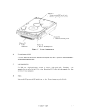
... not affect to achieve a high speed seek. C141-E134-01EN 4 - 7 Do not damage or peel off labels. [Surface P'] • Setting terminal(MP model only) • External operator panel connector [Surface P] • Cable connection [Surface R] • Hole for mounting screw [Surface Q] •...; Hole for mounting screw Figure 4.7 Service clearance area (6) External magnetic field The drive should not be installed near equipment. (8) Others Seals on the DE prevent the DE inside from the dust. Therefore, a leak magnetic flux ...
... not affect to achieve a high speed seek. C141-E134-01EN 4 - 7 Do not damage or peel off labels. [Surface P'] • Setting terminal(MP model only) • External operator panel connector [Surface P] • Cable connection [Surface R] • Hole for mounting screw [Surface Q] •...; Hole for mounting screw Figure 4.7 Service clearance area (6) External magnetic field The drive should not be installed near equipment. (8) Others Seals on the DE prevent the DE inside from the dust. Therefore, a leak magnetic flux ...

Product Manual
Page 60
b) In a system which uses the terminating resistor power supply signal (TERMPWR) on /off sequence a) The order of the power on the SCSI bus, the requirements for +5 VDC given in Figure 4.9 must satisfy the requirement given in Subsection 2.1.3. (For other requirements, see Items (4) and (5) below.) (2) Current waveform (reference...that signal. 4 - 8 C141-E134-01EN 4.2 Power Supply Requirements (1) Allowable input voltage and current The power supply input voltage measured at the power supply connector pin of the IDD (receiving end) must be satisfied between the IDD and at least one of the...
b) In a system which uses the terminating resistor power supply signal (TERMPWR) on /off sequence a) The order of the power on the SCSI bus, the requirements for +5 VDC given in Figure 4.9 must satisfy the requirement given in Subsection 2.1.3. (For other requirements, see Items (4) and (5) below.) (2) Current waveform (reference...that signal. 4 - 8 C141-E134-01EN 4.2 Power Supply Requirements (1) Allowable input voltage and current The power supply input voltage measured at the power supply connector pin of the IDD (receiving end) must be satisfied between the IDD and at least one of the...

Product Manual
Page 61
... (1) c) In a system which does not use the terminating resistor power supply signal (TERMPWR) on the SCSI bus, the requirements for +5 VDC given in Figure 4.10 must be satisfied between that SCSI device and the IDD. SCSI devices with the terminating resistor Figure 4.10 Power on/off sequence (2) d) Between... the IDD and other SCSI devices on the SCSI bus, the +5 VDC ...
... (1) c) In a system which does not use the terminating resistor power supply signal (TERMPWR) on the SCSI bus, the requirements for +5 VDC given in Figure 4.10 must be satisfied between that SCSI device and the IDD. SCSI devices with the terminating resistor Figure 4.10 Power on/off sequence (2) d) Between... the IDD and other SCSI devices on the SCSI bus, the +5 VDC ...

Product Manual
Page 62
...12-second intervals to start the spindle motors. For how to set a spindle motor start the spindle motors sequentially. (5) Power supply to SCSI terminating resistor If power for this command specification, refer to the IDD must be designed with a setting... terminal on the IDD (MP model only). See Subsection 5.3.2 for the terminating resistor is supplied from the IDD to other SCSI devices through the SCSI bus, the current-carrying capacity of the +5 VDC power supply line to SCSI Logical Interface Specifications. For the electrical condition...
...12-second intervals to start the spindle motors. For how to set a spindle motor start the spindle motors sequentially. (5) Power supply to SCSI terminating resistor If power for this command specification, refer to the IDD must be designed with a setting... terminal on the IDD (MP model only). See Subsection 5.3.2 for the terminating resistor is supplied from the IDD to other SCSI devices through the SCSI bus, the current-carrying capacity of the +5 VDC power supply line to SCSI Logical Interface Specifications. For the electrical condition...
Product Manual
Page 63
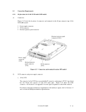
... physical/electrical requirements of connectors and terminals on the SCSI connector. Figure 4.14 shows the SCSI connector. C141-E134-01EN 4 - 11 4.3 Connection Requirements 4.3.1 68 pin connector 16-bit SCSI model (MP model) (1) Connectors Figures 4.13 show the locations of the interface signals, refer to SCSI-3 type which has two 34-pin rows spaced 1.27 mm (0.05 inch...
... physical/electrical requirements of connectors and terminals on the SCSI connector. Figure 4.14 shows the SCSI connector. C141-E134-01EN 4 - 11 4.3 Connection Requirements 4.3.1 68 pin connector 16-bit SCSI model (MP model) (1) Connectors Figures 4.13 show the locations of the interface signals, refer to SCSI-3 type which has two 34-pin rows spaced 1.27 mm (0.05 inch...

Product Manual
Page 64
Power supply connector Figure 4.15 shows the shape and the terminal arrangement of the output connector of DC power supply. The tolerance is not provided with an SG terminal (fasten tab) for DC grounding. Therefore, when connecting SG and FG in the system, use the +5 VDC RETURN (ground) inside the power supply connector as the SG on the power supply side. 4 - 12 C141-E134-01EN Figure 4.15 Power supply connector (16-bit SCSI model) (3) SG terminal The IDD is ±0.127 mm (0.005 inch) unless otherwise specified Figure 4.14 16-bit SCSI interface connector b.
Power supply connector Figure 4.15 shows the shape and the terminal arrangement of the output connector of DC power supply. The tolerance is not provided with an SG terminal (fasten tab) for DC grounding. Therefore, when connecting SG and FG in the system, use the +5 VDC RETURN (ground) inside the power supply connector as the SG on the power supply side. 4 - 12 C141-E134-01EN Figure 4.15 Power supply connector (16-bit SCSI model) (3) SG terminal The IDD is ±0.127 mm (0.005 inch) unless otherwise specified Figure 4.14 16-bit SCSI interface connector b.

Product Manual
Page 68
... to set up the SCSI ID by short circuiting CN1-A3 and CN1-A4, and CN1-A5 and CN1-A6.) These pins get high impedance status except above. This signal is possible to the CN2-21, 22 pin (LED [V] and -LED terminals). 3. The meaning of the disk drive. For details of the... IDD. The electrical requirements are temporarily driven at the GND level when the micro program reads the SCSI ID immediately after the power supply to the IDD has...
... to set up the SCSI ID by short circuiting CN1-A3 and CN1-A4, and CN1-A5 and CN1-A6.) These pins get high impedance status except above. This signal is possible to the CN2-21, 22 pin (LED [V] and -LED terminals). 3. The meaning of the disk drive. For details of the... IDD. The electrical requirements are temporarily driven at the GND level when the micro program reads the SCSI ID immediately after the power supply to the IDD has...