
Product Manual
Page 4
...Specifications and functions of products covered by this manual comply with the following standards. ANSI X3.131-1994 T10/1236-D Rev 19 ANSI NCITS. 306-1998 ANSI X3.270-1996 ANSI NCITS. 336-2000 Name Small Computer System Interface 2(SCSI-2) SCSI Primary Commands-2 (SPC-2) SCSI-3 Block Commands (SBC) SCSI...-3 Architecture Model (SAM) SCSI Parallel Interface-3 (SPI-3) Enacting Organization American National Standards Institute (ANSI) American ...
...Specifications and functions of products covered by this manual comply with the following standards. ANSI X3.131-1994 T10/1236-D Rev 19 ANSI NCITS. 306-1998 ANSI X3.270-1996 ANSI NCITS. 336-2000 Name Small Computer System Interface 2(SCSI-2) SCSI Primary Commands-2 (SPC-2) SCSI-3 Block Commands (SBC) SCSI...-3 Architecture Model (SAM) SCSI Parallel Interface-3 (SPI-3) Enacting Organization American National Standards Institute (ANSI) American ...

Product Manual
Page 5
... have a basic understanding of the MAM series disk drives and their use the other manuals. Chapter 2 SPECIFICATIONS This chapter gives detailed specifications of fixed disk drives and their installation environment. PREFACE This manual describes the MAM3367MC/MP, MAM3184MC/MP (hereafter, MAM series), 3.5 type fixed disk drives with an embedded SCSI controller. Chapter 1 GENERAL DESCRIPTION This chapter introduces...
... have a basic understanding of the MAM series disk drives and their use the other manuals. Chapter 2 SPECIFICATIONS This chapter gives detailed specifications of fixed disk drives and their installation environment. PREFACE This manual describes the MAM3367MC/MP, MAM3184MC/MP (hereafter, MAM series), 3.5 type fixed disk drives with an embedded SCSI controller. Chapter 1 GENERAL DESCRIPTION This chapter introduces...

Product Manual
Page 10
Installation Requirements 5. Data Buffer Management 3. Specifications 3. Diagnostics and Maintenance 7. SCSI Bus Error Recovery Processing SCSI Logical Interface Specifications 1. Command Processing 2. Command Specification 4. Data Format 4. Error Analysis 8. Sense Data and error Recovery Procedure 5. MANUAL ORGANIZATION PRODUCT/ MAINTENANCE MANUAL (This manual) 1. SCSI Message 3. General Description 2. Principle of Operation SCSI Physical Interface Specifications 1. Installation 6. SCSI Bus 2. Disk Medium Management viii C141-E134-01EN
Installation Requirements 5. Data Buffer Management 3. Specifications 3. Diagnostics and Maintenance 7. SCSI Bus Error Recovery Processing SCSI Logical Interface Specifications 1. Command Processing 2. Command Specification 4. Data Format 4. Error Analysis 8. Sense Data and error Recovery Procedure 5. MANUAL ORGANIZATION PRODUCT/ MAINTENANCE MANUAL (This manual) 1. SCSI Message 3. General Description 2. Principle of Operation SCSI Physical Interface Specifications 1. Installation 6. SCSI Bus 2. Disk Medium Management viii C141-E134-01EN

Product Manual
Page 11
...Standard Features ...1-2 1.2 Hardware Structure...1-5 1.3 System Configuration ...1-8 CHAPTER 2 SPECIFICATIONS ...2-1 2.1 Hardware Specifications ...2-1 2.1.1 Model name and part number ...2-1 2.1.2 Function specifications ...2-2 2.1.3 Environmental specifications...2-4 2.1.4 Error rate...2-5 2.1.5 Reliability ...2-5 2.2 SCSI Function Specifications ...2-7 CHAPTER 3 DATA FORMAT...3-1 3.1 Data Space ...3-1 3.1.1 Cylinder ... Notes on mounting...4-4 4.2 Power Supply Requirements...4-8 4.3 Connection Requirements...4-11 4.3.1 68 pin connector 16-bit SCSI model (MP model 4-11 C141-E134-01EN ix
...Standard Features ...1-2 1.2 Hardware Structure...1-5 1.3 System Configuration ...1-8 CHAPTER 2 SPECIFICATIONS ...2-1 2.1 Hardware Specifications ...2-1 2.1.1 Model name and part number ...2-1 2.1.2 Function specifications ...2-2 2.1.3 Environmental specifications...2-4 2.1.4 Error rate...2-5 2.1.5 Reliability ...2-5 2.2 SCSI Function Specifications ...2-7 CHAPTER 3 DATA FORMAT...3-1 3.1 Data Space ...3-1 3.1.1 Cylinder ... Notes on mounting...4-4 4.2 Power Supply Requirements...4-8 4.3 Connection Requirements...4-11 4.3.1 68 pin connector 16-bit SCSI model (MP model 4-11 C141-E134-01EN ix
Product Manual
Page 17
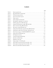
...C.2 Table D.1 page Function specifications...2-2 Environmental/power requirements 2-4 SCSI function specifications 2-7 Zone layout and track capacity 3-3 Format capacity...3-10 Surface temperature check point 4-6 Recommended components for connection 4-21 SCSI ID setting (CN2 on MP model only 5-7 Setting SCSI terminal power supply (MP model... field troubleshooting 6-14 Disk drive troubleshooting 6-15 Definition of sense data...7-3 Setting terminal: CN2 (MP model B-2 SCSI connector (SCA2 type LVD 16-bit SCSI): CN1 C-2 SCSI connector (68 pin type LVD 16-bit SCSI): CN1 C-3 MAN series ...
...C.2 Table D.1 page Function specifications...2-2 Environmental/power requirements 2-4 SCSI function specifications 2-7 Zone layout and track capacity 3-3 Format capacity...3-10 Surface temperature check point 4-6 Recommended components for connection 4-21 SCSI ID setting (CN2 on MP model only 5-7 Setting SCSI terminal power supply (MP model... field troubleshooting 6-14 Disk drive troubleshooting 6-15 Definition of sense data...7-3 Setting terminal: CN2 (MP model B-2 SCSI connector (SCA2 type LVD 16-bit SCSI): CN1 C-2 SCSI connector (68 pin type LVD 16-bit SCSI): CN1 C-3 MAN series ...

Product Manual
Page 19
IDDs are high performance large capacity 3.5 type fixed disk drives with large storage capacity. C141-E134-01EN 1 - 1 CHAPTER 1 GENERAL DESCRIPTION 1.1 Standard Features 1.2 Hardware Structure 1.3 System Configuration This chapter describes the feature and configuration of the IDD, allow the user to SCSI Logical Interface Specifications for details. Refer to construct a high-performance reliable disk subsystem...
IDDs are high performance large capacity 3.5 type fixed disk drives with large storage capacity. C141-E134-01EN 1 - 1 CHAPTER 1 GENERAL DESCRIPTION 1.1 Standard Features 1.2 Hardware Structure 1.3 System Configuration This chapter describes the feature and configuration of the IDD, allow the user to SCSI Logical Interface Specifications for details. Refer to construct a high-performance reliable disk subsystem...

Product Manual
Page 29
CHAPTER 2 SPECIFICATIONS 2.1 Hardware Specifications 2.2 SCSI Function Specifications This chapter describes specifications of the IDD and the functional specifications of the SCSI. 2.1 Hardware Specifications 2.1.1 Model name and part number Each model has a different recording capacities and interface connector type when shipped. (See Appendix D for the model name (type) and product number.) The data format can be changed by reinitializing with the user's system. C141-E134-01EN 2 - 1
CHAPTER 2 SPECIFICATIONS 2.1 Hardware Specifications 2.2 SCSI Function Specifications This chapter describes specifications of the IDD and the functional specifications of the SCSI. 2.1 Hardware Specifications 2.1.1 Model name and part number Each model has a different recording capacities and interface connector type when shipped. (See Appendix D for the model name (type) and product number.) The data format can be changed by reinitializing with the user's system. C141-E134-01EN 2 - 1

Product Manual
Page 30
...SCSI Inter- 2.1.2 Function specifications Table 2.1 shows the function specifications of rotations min-1 (rpm) Average latency time Seek time (*3) (Read/Write) Track to Track Average Full stroke Start/stop time Start time (*4) Stop time Recording mode External dimensions Height: Width: Depth: Weight (max) Power consumption (*5) Fast 5 SCSI Specification... length: 12 m max (*9) Data transfer rate (*10) Disk drive SCSI Synchronous mode 68.6 to 528 byte (Fixed length) ANSI X3.131-1994 conformity SCSI command specification SPC-2 (T10/1236-D Rev 19), SBC (ANSI NCITS.306-1998...
...SCSI Inter- 2.1.2 Function specifications Table 2.1 shows the function specifications of rotations min-1 (rpm) Average latency time Seek time (*3) (Read/Write) Track to Track Average Full stroke Start/stop time Start time (*4) Stop time Recording mode External dimensions Height: Width: Depth: Weight (max) Power consumption (*5) Fast 5 SCSI Specification... length: 12 m max (*9) Data transfer rate (*10) Disk drive SCSI Synchronous mode 68.6 to 528 byte (Fixed length) ANSI X3.131-1994 conformity SCSI command specification SPC-2 (T10/1236-D Rev 19), SBC (ANSI NCITS.306-1998...

Product Manual
Page 32
... within +12 VDC 100 µs at ±5% spin-up Power Random requirements W/R Input power (about 80 (*5) IOPS) Ready +5 VDC ±5% (*6) Random W/R (about 80 IOPS) Ripple (*7) Specification MAM3367 series MAM3184 series 5 to 50°C -10 to 60°C -40 to 60°C ... to 12,000 m 0.78 A 0.61 A 3.0 A 1.0 A 0.8 A 0.4 A 1.0 A +5 V/+12 V 250 mVp-p (*1) For detail condition, see Section 4.1. (*2) Vibration applied to the drive is measured at near the mounting screw hole on the frame as much as possible. (*3) At random seek write/read and default on retry setting...
... within +12 VDC 100 µs at ±5% spin-up Power Random requirements W/R Input power (about 80 (*5) IOPS) Ready +5 VDC ±5% (*6) Random W/R (about 80 IOPS) Ripple (*7) Specification MAM3367 series MAM3184 series 5 to 50°C -10 to 60°C -40 to 60°C ... to 12,000 m 0.78 A 0.61 A 3.0 A 1.0 A 0.8 A 0.4 A 1.0 A +5 V/+12 V 250 mVp-p (*1) For detail condition, see Section 4.1. (*2) Vibration applied to the drive is measured at near the mounting screw hole on the frame as much as possible. (*3) At random seek write/read and default on retry setting...

Product Manual
Page 35
... max. Ο 40 MB/s max. Ο 80 MB/s max. Ο 160 MB/s max. 2.2 SCSI Function Specifications Table 2.3 shows the SCSI functions provided with the IDD. Table 2.3 SCSI function specifications Item Specification Single-ended type Ο HVD type (High Voltage ...80 pin SCA2 connector Ο (MP model) Ο (MC model) Data bus parity (Data bus CRC) Ο Bus arbitration function Ο Disconnection/reconnection function Ο Addressing SCSI ID 16-bit SCSI LUN (logical unit number) 8-bit SCSI (Single-Ended type) Data transfer (LVD type) (Synchronous 16-bit SCSI...
... max. Ο 40 MB/s max. Ο 80 MB/s max. Ο 160 MB/s max. 2.2 SCSI Function Specifications Table 2.3 shows the SCSI functions provided with the IDD. Table 2.3 SCSI function specifications Item Specification Single-ended type Ο HVD type (High Voltage ...80 pin SCA2 connector Ο (MP model) Ο (MC model) Data bus parity (Data bus CRC) Ο Bus arbitration function Ο Disconnection/reconnection function Ο Addressing SCSI ID 16-bit SCSI LUN (logical unit number) 8-bit SCSI (Single-Ended type) Data transfer (LVD type) (Synchronous 16-bit SCSI...

Product Manual
Page 37
... 3.2 Logical Data Block Addressing 3.3 Defect Management This chapter explains data space definition, logical data block addressing, and defect management on or during the execution of a specific command, but user can be accessed with the logical data block addressing method described in the user space. Several sectors in the last track of...
... 3.2 Logical Data Block Addressing 3.3 Defect Management This chapter explains data space definition, logical data block addressing, and defect management on or during the execution of a specific command, but user can be accessed with the logical data block addressing method described in the user space. Several sectors in the last track of...

Product Manual
Page 48
... spare sectors in the alternate cylinder are allocated to OEM Manual-SCSI Logical Specifications-for spare sectors by the MODE SELECT command at the time of the initialization of the disk. The INIT can specify the size and area for details of specifications on the same cylinder as the defective sector's and is...
... spare sectors in the alternate cylinder are allocated to OEM Manual-SCSI Logical Specifications-for spare sectors by the MODE SELECT command at the time of the initialization of the disk. The INIT can specify the size and area for details of specifications on the same cylinder as the defective sector's and is...

Product Manual
Page 56
...; from the IDD frame wall at the corner must be 6.35 mm or less. d) Impact caused by the electric driver must be within the device specifications. 4 - 4 C141-E134-01EN Mount the IDD with making a gap of 2.5 mm or more between the IDD and the frame of the screw from the horizontal...
...; from the IDD frame wall at the corner must be 6.35 mm or less. d) Impact caused by the electric driver must be within the device specifications. 4 - 4 C141-E134-01EN Mount the IDD with making a gap of 2.5 mm or more between the IDD and the frame of the screw from the horizontal...

Product Manual
Page 58
... the sides which must allow access to the IDD for installation or maintenance, is indicated with air circulation inside the cabinet. Measurement point 1 Center of specific ICs and the DE. At designing the system cabinet, consider following points. • Make a suitable air flow so that the DE surface temperature does not...
... the sides which must allow access to the IDD for installation or maintenance, is indicated with air circulation inside the cabinet. Measurement point 1 Center of specific ICs and the DE. At designing the system cabinet, consider following points. • Make a suitable air flow so that the DE surface temperature does not...

Product Manual
Page 62
...Attenuation: 40 dB or more at more than 12-second intervals to start control mode, see Subsection 5.3.2. The specification of up to 200 mA. Therefore, if more than one of the following procedures to prevent overload of power ...sequentially using one IDD is selected with considering of an increase of this noise filter is as shown in SCSI Physical Interface Specifications. (6) Noise filter To eliminate AC line noise, a noise filter should be designed with a setting terminal...power is turned on to the IDD, a large amount of this command specification, refer to SCSI Logical Interface...
...Attenuation: 40 dB or more at more than 12-second intervals to start control mode, see Subsection 5.3.2. The specification of up to 200 mA. Therefore, if more than one of the following procedures to prevent overload of power ...sequentially using one IDD is selected with considering of an increase of this noise filter is as shown in SCSI Physical Interface Specifications. (6) Noise filter To eliminate AC line noise, a noise filter should be designed with a setting terminal...power is turned on to the IDD, a large amount of this command specification, refer to SCSI Logical Interface...
Product Manual
Page 63
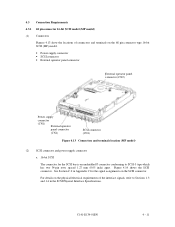
... 4 - 11 For details on the SCSI connector. See Section C.2 in the SCSI Physical Interface Specifications. 4.3 Connection Requirements 4.3.1 68 pin connector 16-bit SCSI model (MP model) (1) Connectors Figures 4.13 show the locations of connectors and terminals on the 68 pin connector type 16-bit SCSI (MP) model. • Power supply connector • SCSI connector • External operator panel...
... 4 - 11 For details on the SCSI connector. See Section C.2 in the SCSI Physical Interface Specifications. 4.3 Connection Requirements 4.3.1 68 pin connector 16-bit SCSI model (MP model) (1) Connectors Figures 4.13 show the locations of connectors and terminals on the 68 pin connector type 16-bit SCSI (MP) model. • Power supply connector • SCSI connector • External operator panel...

Product Manual
Page 68
... Specifications. 2. Any load other than the external LED (see Subsection 4.3.5) should not be selected with the CHANGE DEFINITION command. This signal is possible to set up the SCSI ID by short circuiting CN1-A1 and CN1-A2.) c. CN1-A6 (reserved) These pins are short-circuited.) A signal for driving the... LED is output. 74LS06 or equivalent 150 Ω (IDD) CN1-A2 IMPORTANT This signal is temporarily driven at the GND level when the micro program reads the SCSI ID immediately after the power supply to...
... Specifications. 2. Any load other than the external LED (see Subsection 4.3.5) should not be selected with the CHANGE DEFINITION command. This signal is possible to set up the SCSI ID by short circuiting CN1-A1 and CN1-A2.) c. CN1-A6 (reserved) These pins are short-circuited.) A signal for driving the... LED is output. 74LS06 or equivalent 150 Ω (IDD) CN1-A2 IMPORTANT This signal is temporarily driven at the GND level when the micro program reads the SCSI ID immediately after the power supply to...

Product Manual
Page 71
... (CN1) Figure 4.21 Connectors location of connectors on the SCA2 type SCSI model. C141-E134-01EN 4 - 19 See Section C.5 in SCSI Physical Interface Specifications. SCA type SCSI The connector for the SCSI bus is an unshielded SCA-2 connector conforming to Sections 1.3 and 1.4 in Appendix C for ...the physical/electrical requirements of the interface signals, refer to SCSI-3 type which has two 40-pin rows spaced 1.27 mm (0.05 inch) apart. Figure 4.22 shows the SCSI connector. For details on the connector. 4.3.2 SCA2 type SCSI model (MC model) (1) Connectors Figure 4.21 shows the...
... (CN1) Figure 4.21 Connectors location of connectors on the SCA2 type SCSI model. C141-E134-01EN 4 - 19 See Section C.5 in SCSI Physical Interface Specifications. SCA type SCSI The connector for the SCSI bus is an unshielded SCA-2 connector conforming to Sections 1.3 and 1.4 in Appendix C for ...the physical/electrical requirements of the interface signals, refer to SCSI-3 type which has two 40-pin rows spaced 1.27 mm (0.05 inch) apart. Figure 4.22 shows the SCSI connector. For details on the connector. 4.3.2 SCA2 type SCSI model (MC model) (1) Connectors Figure 4.21 shows the...

Product Manual
Page 73
... (AWG26 to 36) FCN-723J016/2M FUJITSU TAKAMIZAWA FCN-723J-G/AM FUJITSU TAKAMIZAWA (AWG28) 71780-003 FCI Reference (Figures 4.25 and 4.30) S1 S2 S3 S4 (1) SCSI cable See Section 1.3, "Physical Requirements", and Section 1.4, "Electrical Requirements", in SCSI Physical Interface Specifications. (2) Power cable IDDs must always be...connected in CN1. When connection is not required, leave open the following pins in the external operator panel connector of the IDD : Pins 21, 22 and pins 01 through 08 in CN2 and pins A1 through A12 in the system, it is necessary to connect SG ...
... (AWG26 to 36) FCN-723J016/2M FUJITSU TAKAMIZAWA FCN-723J-G/AM FUJITSU TAKAMIZAWA (AWG28) 71780-003 FCI Reference (Figures 4.25 and 4.30) S1 S2 S3 S4 (1) SCSI cable See Section 1.3, "Physical Requirements", and Section 1.4, "Electrical Requirements", in SCSI Physical Interface Specifications. (2) Power cable IDDs must always be...connected in CN1. When connection is not required, leave open the following pins in the external operator panel connector of the IDD : Pins 21, 22 and pins 01 through 08 in CN2 and pins A1 through A12 in the system, it is necessary to connect SG ...
Product Manual
Page 75
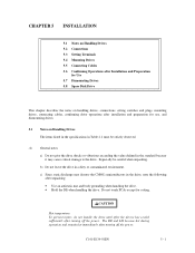
... contaminated environment. C141-E134-01EN 5 - 1 CHAPTER 5 INSTALLATION 5.1 Notes on Handling Drives 5.2 Connections 5.3 Setting Terminals 5.4 Mounting Drives 5.5 Connecting Cables 5.6 Confirming Operations after Installation and Preparation for Use 5.7 Dismounting Drives 5.8 Spare Disk Drive This chapter describes the notes on Handling Drives The items listed in the specifications in Table 2.1 must be careful when unpacking. b) Do not leave the...
... contaminated environment. C141-E134-01EN 5 - 1 CHAPTER 5 INSTALLATION 5.1 Notes on Handling Drives 5.2 Connections 5.3 Setting Terminals 5.4 Mounting Drives 5.5 Connecting Cables 5.6 Confirming Operations after Installation and Preparation for Use 5.7 Dismounting Drives 5.8 Spare Disk Drive This chapter describes the notes on Handling Drives The items listed in the specifications in Table 2.1 must be careful when unpacking. b) Do not leave the...
