Manual/User Guide
Page 5
... Systems-Small Computer Standards Institute System Interface (SCSI) (ANSI) American National Standard for American National Information Systems-Small Computer Standards Institute System Interface - 2(SCSI-2) (ANSI) COMMON COMMAND SET (CCS) of...SCSI-3 Block Standards Institute Commands (SBC) (ANSI) WORKING DRAFT Information American National technology SCSI-3 Architecture Model Standards Institute (SAM) (ANSI) WORKING DRAFT Information technology SCSI Parallel Interface-3 (SPI-3) American National Standards Institute (ANSI) All Right Reserved, Copyright © 2000 Fujitsu...
... Systems-Small Computer Standards Institute System Interface (SCSI) (ANSI) American National Standard for American National Information Systems-Small Computer Standards Institute System Interface - 2(SCSI-2) (ANSI) COMMON COMMAND SET (CCS) of...SCSI-3 Block Standards Institute Commands (SBC) (ANSI) WORKING DRAFT Information American National technology SCSI-3 Architecture Model Standards Institute (SAM) (ANSI) WORKING DRAFT Information technology SCSI Parallel Interface-3 (SPI-3) American National Standards Institute (ANSI) All Right Reserved, Copyright © 2000 Fujitsu...
Manual/User Guide
Page 6
... disk drive, connecting the cables, and confirming drive operation....drives and discusses their installation environment. Chapter 8 PRINCIPLE OF OPERATION This chapter explains disk drives configuration and operation of the above disk drive..., and gives the requirements and procedures for operation check and the basics of MAH series and MAJ series disk drive... of troubleshooting the disk drives. This chapter also describes... series disk drives. The need arises... fixed disk drives and their...and MAJ series disk drives. This manual is ...
... disk drive, connecting the cables, and confirming drive operation....drives and discusses their installation environment. Chapter 8 PRINCIPLE OF OPERATION This chapter explains disk drives configuration and operation of the above disk drive..., and gives the requirements and procedures for operation check and the basics of MAH series and MAJ series disk drive... of troubleshooting the disk drives. This chapter also describes... series disk drives. The need arises... fixed disk drives and their...and MAJ series disk drives. This manual is ...
Manual/User Guide
Page 7
... does not perform the procedure correctly. NOTICE NOTICE indicates that describes the electrical requirements of model names and product numbers, and SCSI interface functions. Indicates vi C141-E103-02EN APPENDIX A to D The appendixes give supplementary information, including the locations of mounting ... terminals and connectors, a list of setting items, the signal assignments of interface connectors, lists of the SCSI interface between host system and disk drive, the data formatted at the factory and device type. CONVENTIONS This manual uses the following conventions for alerts...
... does not perform the procedure correctly. NOTICE NOTICE indicates that describes the electrical requirements of model names and product numbers, and SCSI interface functions. Indicates vi C141-E103-02EN APPENDIX A to D The appendixes give supplementary information, including the locations of mounting ... terminals and connectors, a list of setting items, the signal assignments of interface connectors, lists of the SCSI interface between host system and disk drive, the data formatted at the factory and device type. CONVENTIONS This manual uses the following conventions for alerts...
Manual/User Guide
Page 8
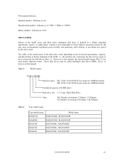
Fujitsu is . However, in this manual, the typical model names (Note 2) are used unless otherwise noted. Hand Disk Drive Type AH: Number of rotations 7,200min-1 (7,200rpm) AJ: Number of the SCSI, i.e., the interface for drive failures caused by misuse by the user, poor environmental ... MAJ3364MP MAJ3182 MAJ3182MC, MAJ3182MP MAJ3091 MAJ3091MC, MAJ3091MP C141-E103-02EN vii Note 1: Model names M AJ 3 364 MC Interface types MC: LVD, 16-bit SCSI SCA2 connector 160MHz transfer MP: LVD, 16-bit SCSI 68 pin connector 160MHz transfer Formatted capacity (100 MB units) Disk drive ...
Fujitsu is . However, in this manual, the typical model names (Note 2) are used unless otherwise noted. Hand Disk Drive Type AH: Number of rotations 7,200min-1 (7,200rpm) AJ: Number of the SCSI, i.e., the interface for drive failures caused by misuse by the user, poor environmental ... MAJ3364MP MAJ3182 MAJ3182MC, MAJ3182MP MAJ3091 MAJ3091MC, MAJ3091MP C141-E103-02EN vii Note 1: Model names M AJ 3 364 MC Interface types MC: LVD, 16-bit SCSI SCA2 connector 160MHz transfer MP: LVD, 16-bit SCSI 68 pin connector 160MHz transfer Formatted capacity (100 MB units) Disk drive ...
Manual/User Guide
Page 9
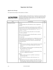
... other property may not be corrected. [Total maximum byte: 5 byte x 4 ( interleave) = 20 byte] If the error of the SCSI connectors. The sector-data is divided into 4 interleaving sectors, and ECC is performed. However, if error byte exceeds its allowable number, correction ...procedure correctly. Do not change setting status set at factory shipment. 2. Hot temperature 5-1 To prevent injury, do not handle the drive until after the device has cooled sufficiently after turning off the power. Data loss 5-5 1. Important Alert Items Important Alert Messages ...
... other property may not be corrected. [Total maximum byte: 5 byte x 4 ( interleave) = 20 byte] If the error of the SCSI connectors. The sector-data is divided into 4 interleaving sectors, and ECC is performed. However, if error byte exceeds its allowable number, correction ...procedure correctly. Do not change setting status set at factory shipment. 2. Hot temperature 5-1 To prevent injury, do not handle the drive until after the device has cooled sufficiently after turning off the power. Data loss 5-5 1. Important Alert Items Important Alert Messages ...
Manual/User Guide
Page 10
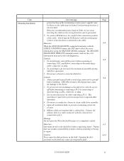
... not use a conductive cleaner to pin 1. To prevent electrical damage to clean the disk drive. Ribbon cables are used, inserting the cables in Table 4.2 are marked with a colored line. Fujitsu does not assume responsibility if data is the last device connected to prevent overheating of the...removing a PCA. To avoid injury, do not touch the mechanical assembly during servicing or repair. Check that the SCSI device with the colored wire connected to clean a disk drive assembly. 5. C141-E103-02EN ix To avoid shocks, turn the power off the power before mounting or 6-5...
... not use a conductive cleaner to pin 1. To prevent electrical damage to clean the disk drive. Ribbon cables are used, inserting the cables in Table 4.2 are marked with a colored line. Fujitsu does not assume responsibility if data is the last device connected to prevent overheating of the...removing a PCA. To avoid injury, do not touch the mechanical assembly during servicing or repair. Check that the SCSI device with the colored wire connected to clean a disk drive assembly. 5. C141-E103-02EN ix To avoid shocks, turn the power off the power before mounting or 6-5...
Manual/User Guide
Page 11
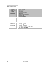
General Description 2. Installation Requirements 5. Error Analysis 8. SCSI Bus 2. Command Specification 4. Data Format 4. Diagnostics and Maintenance 7. Sense Data and error Recovery Procedure 5. Command Processing 2. Specifications 3. Installation 6. Principle of Operation 1. Disk Medium Management x C141-E103-02EN MANUAL ORGANIZATION PRODUCT/ MAINTENANCE MANUAL (This manual) SCSI Physical Interface Specifications SCSI Logical Interface Specifications 1. SCSI Bus Error Recovery Processing 1. Data Buffer Management 3. SCSI Message 3.
General Description 2. Installation Requirements 5. Error Analysis 8. SCSI Bus 2. Command Specification 4. Data Format 4. Diagnostics and Maintenance 7. Sense Data and error Recovery Procedure 5. Command Processing 2. Specifications 3. Installation 6. Principle of Operation 1. Disk Medium Management x C141-E103-02EN MANUAL ORGANIZATION PRODUCT/ MAINTENANCE MANUAL (This manual) SCSI Physical Interface Specifications SCSI Logical Interface Specifications 1. SCSI Bus Error Recovery Processing 1. Data Buffer Management 3. SCSI Message 3.
Manual/User Guide
Page 12
... Standard Features ...1-2 1.2 Hardware Structure...1-5 1.3 System Configuration ...1-9 CHAPTER 2 SPECIFICATIONS 2-1 2.1 Hardware Specifications...2-1 2.1.1 Model name and part number 2-1 2.1.2 Function specifications...2-2 2.1.3 Environmental specifications 2-4 2.1.4 Error rate ...2-5 2.1.5 Reliability...2-5 2.2 SCSI Function Specifications 2-7 CHAPTER 3 DATA FORMAT 3-1 3.1 Data Space...3-1 3.1.1 Cylinder configuration...3-1 3.1.2 Alternate spare area...3-5 3.1.3 Track format...3-6 3.1.4 Sector format ...3-8 3.1.5 Format capacity ...3-10 3.2 Logical Data Block Addressing 3-11 3.3 Defect...
... Standard Features ...1-2 1.2 Hardware Structure...1-5 1.3 System Configuration ...1-9 CHAPTER 2 SPECIFICATIONS 2-1 2.1 Hardware Specifications...2-1 2.1.1 Model name and part number 2-1 2.1.2 Function specifications...2-2 2.1.3 Environmental specifications 2-4 2.1.4 Error rate ...2-5 2.1.5 Reliability...2-5 2.2 SCSI Function Specifications 2-7 CHAPTER 3 DATA FORMAT 3-1 3.1 Data Space...3-1 3.1.1 Cylinder configuration...3-1 3.1.2 Alternate spare area...3-5 3.1.3 Track format...3-6 3.1.4 Sector format ...3-8 3.1.5 Format capacity ...3-10 3.2 Logical Data Block Addressing 3-11 3.3 Defect...
Manual/User Guide
Page 13
... procedures...5-10 5.5 Connecting Cables...5-11 5.6 Confirming Operations after Installation and Preparation for use 5-12 5.6.1 Confirming initial operations 5-12 5.6.2 Checking SCSI connection...5-13 5.6.3 Formatting ...5-16 5.6.4 Setting parameters ...5-18 5.7 Dismounting Drives...5-22 5.8 Spare Disk Drive ...5-22 CHAPTER 6 DIAGNOSTICS AND MAINTENANCE 6-1 6.1 Diagnostics ...6-1 6.1.1 Self-diagnostics ...6-1 6.1.2 Test programs...6-4 6.2 Maintenance Information ...6-5 6.2.1 Precautions ...6-5 6.2.2 Maintenance requirements...6-6 6.2.3 Maintenance levels ...6-8 6.2.4 Revision numbers...
... procedures...5-10 5.5 Connecting Cables...5-11 5.6 Confirming Operations after Installation and Preparation for use 5-12 5.6.1 Confirming initial operations 5-12 5.6.2 Checking SCSI connection...5-13 5.6.3 Formatting ...5-16 5.6.4 Setting parameters ...5-18 5.7 Dismounting Drives...5-22 5.8 Spare Disk Drive ...5-22 CHAPTER 6 DIAGNOSTICS AND MAINTENANCE 6-1 6.1 Diagnostics ...6-1 6.1.1 Self-diagnostics ...6-1 6.1.2 Test programs...6-4 6.2 Maintenance Information ...6-5 6.2.1 Precautions ...6-5 6.2.2 Maintenance requirements...6-6 6.2.3 Maintenance levels ...6-8 6.2.4 Revision numbers...
Manual/User Guide
Page 14
...Diagnostic test ...6-12 Troubleshooting Procedures 6-13 Outline of troubleshooting procedures 6-13 Troubleshooting with disk drive replacement in the field 6-13 Troubleshooting at the repair site 6-15 Troubleshooting with parts ...Sense data (5-2x-xx), (5-3D-00), (5-90-00), (B-47-xx), (B-49-00), (B-4D-xx) and (B-4E-00): SCSI interface error 7-4 CHAPTER 8 PRINCIPLE OF OPERATION 8-1 8.1 Outline...8-1 8.2 Disk Drive Configuration ...8-1 8.2.1 Disks...8-2 8.2.2 Heads...8-2 8.2.3 Spindle mechanism...8-2 8.2.4 Actuator...8-2 8.2.5 Air filters ...8-2 8.3 Circuit Configuration...8-3 8.4 Power-On...
...Diagnostic test ...6-12 Troubleshooting Procedures 6-13 Outline of troubleshooting procedures 6-13 Troubleshooting with disk drive replacement in the field 6-13 Troubleshooting at the repair site 6-15 Troubleshooting with parts ...Sense data (5-2x-xx), (5-3D-00), (5-90-00), (B-47-xx), (B-49-00), (B-4D-xx) and (B-4E-00): SCSI interface error 7-4 CHAPTER 8 PRINCIPLE OF OPERATION 8-1 8.1 Outline...8-1 8.2 Disk Drive Configuration ...8-1 8.2.1 Disks...8-2 8.2.2 Heads...8-2 8.2.3 Spindle mechanism...8-2 8.2.4 Actuator...8-2 8.2.5 Air filters ...8-2 8.3 Circuit Configuration...8-3 8.4 Power-On...
Manual/User Guide
Page 15
... of Connectors and Setting Terminals (MAJ series MP model A-5 APPENDIX B SETTING TERMINALS B-1 B.1 Setting Terminals ...B-2 APPENDIX C CONNECTOR SIGNAL ALLOCATION C-1 C.1 SCSI Connector Signal Allocation: SCA2 type LVD 16-bit SCSI C-2 C.2 SCSI Connector Signal Allocation: 68 pin type LVD 16-bit SCSI C-3 APPENDIX D MODEL NAMES AND PRODUCT NUMBERS D-1 D.1 Model Names and Product Numbers D-2 xiv C141-E103-02EN
... of Connectors and Setting Terminals (MAJ series MP model A-5 APPENDIX B SETTING TERMINALS B-1 B.1 Setting Terminals ...B-2 APPENDIX C CONNECTOR SIGNAL ALLOCATION C-1 C.1 SCSI Connector Signal Allocation: SCA2 type LVD 16-bit SCSI C-2 C.2 SCSI Connector Signal Allocation: 68 pin type LVD 16-bit SCSI C-3 APPENDIX D MODEL NAMES AND PRODUCT NUMBERS D-1 D.1 Model Names and Product Numbers D-2 xiv C141-E103-02EN
Manual/User Guide
Page 16
... sequence (2)...4-12 4.14 Power on/off sequence (3)...4-12 4.15 AC noise filter (recommended 4-13 4.16 Connectors and terminals location (MP model 4-14 4.17 16-bit SCSI interface connector 4-15 4.18 Power supply connector (16-bit SCSI model 4-15 4.19 External operator panel connector (CN1 4-16 C141-E103-02EN xv
... sequence (2)...4-12 4.14 Power on/off sequence (3)...4-12 4.15 AC noise filter (recommended 4-13 4.16 Connectors and terminals location (MP model 4-14 4.17 16-bit SCSI interface connector 4-15 4.18 Power supply connector (16-bit SCSI model 4-15 4.19 External operator panel connector (CN1 4-16 C141-E103-02EN xv
Manual/User Guide
Page 17
... 4-23 4.26 External operator panel connector (CN2 4-24 4.27 16-bit SCSI ID external input 4-25 4.28 External operator panel circuit example 4-27 5.1 SCSI bus connections...5-3 5.2 IDD setting terminals position 5-5 5.3 Setting terminals (CN2)...5-6 5.4 Checking the SCSI connection (A 5-14 5.5 Checking the SCSI connection (B 5-15 6.1 Revision label...6-9 6.2 Indicating revision numbers 6-10 6.3 Test flowchart...6-11 7.1 Format of...
... 4-23 4.26 External operator panel connector (CN2 4-24 4.27 16-bit SCSI ID external input 4-25 4.28 External operator panel circuit example 4-27 5.1 SCSI bus connections...5-3 5.2 IDD setting terminals position 5-5 5.3 Setting terminals (CN2)...5-6 5.4 Checking the SCSI connection (A 5-14 5.5 Checking the SCSI connection (B 5-15 6.1 Revision label...6-9 6.2 Indicating revision numbers 6-10 6.3 Test flowchart...6-11 7.1 Format of...
Manual/User Guide
Page 18
... mode setting...5-8 5.4 Write protect setting (CN2 5-8 5.5 Setting of the SCSI interface operation mode (CN2 5-9 5.6 Setting the bus width of the SCSI interface (CN2 5-9 5.7 Default mode settings (by CHANGE DEFINITION command 5-9 5.8 Setting check list ...5-10 6.1 Self-diagnostic functions ...6-1 6.2 System-level field troubleshooting 6-14 6.3 Disk drive troubleshooting ...6-15 7.1 Definition of sense data ...7-3 8.1 MAJ3364 series, MAJ3182...
... mode setting...5-8 5.4 Write protect setting (CN2 5-8 5.5 Setting of the SCSI interface operation mode (CN2 5-9 5.6 Setting the bus width of the SCSI interface (CN2 5-9 5.7 Default mode settings (by CHANGE DEFINITION command 5-9 5.8 Setting check list ...5-10 6.1 Self-diagnostic functions ...6-1 6.2 System-level field troubleshooting 6-14 6.3 Disk drive troubleshooting ...6-15 7.1 Definition of sense data ...7-3 8.1 MAJ3364 series, MAJ3182...
Manual/User Guide
Page 20
... as the powerful command set of the intelligent disk drives (IDD). CHAPTER 1 GENERAL DESCRIPTION 1.1 Standard Features 1.2 Hardware Structure 1.3 System Configuration This chapter describes the feature and configuration of the IDD, allow the user to construct a high-performance reliable disk subsystem with an embedded SCSI controller. The interface between the IDD and host...
... as the powerful command set of the intelligent disk drives (IDD). CHAPTER 1 GENERAL DESCRIPTION 1.1 Standard Features 1.2 Hardware Structure 1.3 System Configuration This chapter describes the feature and configuration of the IDD, allow the user to construct a high-performance reliable disk subsystem with an embedded SCSI controller. The interface between the IDD and host...
Manual/User Guide
Page 21
...The IDD can be connected directly to accommodate future expansion of system functions. (3) 8-bit SCSI/16-bit SCSI The IDD has 16-bit data bus width (16-bit SCSI), which meets the logical specification of the disk drive. This is also available as follows. (4) High speed data transfer • 8-bit... SCSI: The data transfer rate on the SCSI bus is 40 MB/s maximum in synchronous mode. • 16-bit SCSI: The data transfer rate on the SCSI bus can be useful with...
...The IDD can be connected directly to accommodate future expansion of system functions. (3) 8-bit SCSI/16-bit SCSI The IDD has 16-bit data bus width (16-bit SCSI), which meets the logical specification of the disk drive. This is also available as follows. (4) High speed data transfer • 8-bit... SCSI: The data transfer rate on the SCSI bus is 40 MB/s maximum in synchronous mode. • 16-bit SCSI: The data transfer rate on the SCSI bus can be useful with...

Manual/User Guide
Page 22
...in a command can be achieved, and IDD can perform continuous read/write operation when processing data blocks on the SCSI bus by specifying the condition of the disk drive. (7) Read-ahead cache feature After executing the READ command, the IDD reads automatically and stores (prefetches) the ...segment data buffer The data buffer is adopted to prevent a specific command from the data buffer without concerning the physical structure of SCSI bus length. The data buffer is logical block address. Since the initiator can perform the effective input/output operations with utilizing high ...
...in a command can be achieved, and IDD can perform continuous read/write operation when processing data blocks on the SCSI bus by specifying the condition of the disk drive. (7) Read-ahead cache feature After executing the READ command, the IDD reads automatically and stores (prefetches) the ...segment data buffer The data buffer is adopted to prevent a specific command from the data buffer without concerning the physical structure of SCSI bus length. The data buffer is logical block address. Since the initiator can perform the effective input/output operations with utilizing high ...
Manual/User Guide
Page 23
... the host system can start and stop the spindle motor. (17) Diagnosis The IDD has a diagnostic capability which checks internal controller functions and drive operations to facilitate testing and repair. 1 - 4 C141-E103-02EN This results in high speed contiguous data block processing without a revolution delay... corrected in the data buffer. If a recoverable data check occurs, error-free data can try to recover from errors in SCSI bus or the disk drive using its alternate data block. (12) Programmable data block length Data can be obtained from the complicated error recover processing by...
... the host system can start and stop the spindle motor. (17) Diagnosis The IDD has a diagnostic capability which checks internal controller functions and drive operations to facilitate testing and repair. 1 - 4 C141-E103-02EN This results in high speed contiguous data block processing without a revolution delay... corrected in the data buffer. If a recoverable data check occurs, error-free data can try to recover from errors in SCSI bus or the disk drive using its alternate data block. (12) Programmable data block length Data can be obtained from the complicated error recover processing by...
Manual/User Guide
Page 27
... reliability. (7) Controller circuit The controller circuit uses LSIs to increase the reliability and uses a high speed microprocessing unit (MPU) to increase the performance of the SCSI controller. 1 - 8 C141-E103-02EN The DE has a closed-loop air recirculation system. This filter will trap any dust generated inside the enclosure and keep the...
... reliability. (7) Controller circuit The controller circuit uses LSIs to increase the reliability and uses a high speed microprocessing unit (MPU) to increase the performance of the SCSI controller. 1 - 8 C141-E103-02EN The DE has a closed-loop air recirculation system. This filter will trap any dust generated inside the enclosure and keep the...
Manual/User Guide
Page 28
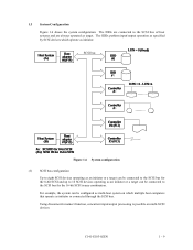
...9 For example, the system can be connected to the SCSI bus for the 16-bit SCSI in any combination. 1.3 System Configuration Figure 1.6 shows the system configuration. The IDDs perform input/output operation as specified by SCSI devices which multiple host computers that operate as an initiator ...or a target can be configured as multi-host system on multi-SCSI devices. Using disconnect/reconnect function, concurrent input/output processing ...
...9 For example, the system can be connected to the SCSI bus for the 16-bit SCSI in any combination. 1.3 System Configuration Figure 1.6 shows the system configuration. The IDDs perform input/output operation as specified by SCSI devices which multiple host computers that operate as an initiator ...or a target can be configured as multi-host system on multi-SCSI devices. Using disconnect/reconnect function, concurrent input/output processing ...

