
Operator Manual
Page 3
... 1.5 Technical data 13 2 Overview: Installation Procedure 15 3 Important notes 17 3.1 Notes on safety 17 3.2 CE conformity 20 3.3 Environmental protection 20 4 Installing the Hardware 23 4.1 Installation Steps 23 4.2 Unpacking the Server Blade 23 4.3 Installing the Server Blade in the Basic Unit 24 4.4 Connecting Devices 28 5 Installation and Operation 31 5.1 Control and Connection Panel 32 5.2 Switching the Server Blade On/Off 35 5.3 Configuring the Server Blade 35 5.4 Updating the Firmware (BIOS and BMC 38 BX630 S2 Operating Manual
... 1.5 Technical data 13 2 Overview: Installation Procedure 15 3 Important notes 17 3.1 Notes on safety 17 3.2 CE conformity 20 3.3 Environmental protection 20 4 Installing the Hardware 23 4.1 Installation Steps 23 4.2 Unpacking the Server Blade 23 4.3 Installing the Server Blade in the Basic Unit 24 4.4 Connecting Devices 28 5 Installation and Operation 31 5.1 Control and Connection Panel 32 5.2 Switching the Server Blade On/Off 35 5.3 Configuring the Server Blade 35 5.4 Updating the Firmware (BIOS and BMC 38 BX630 S2 Operating Manual

Operator Manual
Page 4
...6.4.4 6.4.4.1 6.5 6.6 6.6.1 6.6.2 6.6.3 6.7 6.8 Entering the BIOS Setup 43 Operation 44 Main menu 46 Advanced menu 48 Peripheral Configuration 50 Advanced System Configuration 53 Power On/Off menu 54 IPMI menu 56 IPMI LAN parameters 59 Security menu 60 Server menu 63 CPU Status 65 Memory Status 67 Console Redirection 69 Boot menu 71 Exit menu 72 7 Troubleshooting and Tips 73 8 Hot-plug components 75 8.1 Hot-plug disk drives 75 8.2 Handling hard disk drives and HDD modules 77 8.3 Installing/removing the dummy module 78 8.4 Installing/removing a hard disk module...
...6.4.4 6.4.4.1 6.5 6.6 6.6.1 6.6.2 6.6.3 6.7 6.8 Entering the BIOS Setup 43 Operation 44 Main menu 46 Advanced menu 48 Peripheral Configuration 50 Advanced System Configuration 53 Power On/Off menu 54 IPMI menu 56 IPMI LAN parameters 59 Security menu 60 Server menu 63 CPU Status 65 Memory Status 67 Console Redirection 69 Boot menu 71 Exit menu 72 7 Troubleshooting and Tips 73 8 Hot-plug components 75 8.1 Hot-plug disk drives 75 8.2 Handling hard disk drives and HDD modules 77 8.3 Installing/removing the dummy module 78 8.4 Installing/removing a hard disk module...

Operator Manual
Page 5
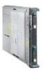
... The PRIMERGY BX630 S2 server blade is designed for the BX600 S3 basic unit, but it can be used. Two BX630 S2 dual-socket server blades can be installed in the BIOS Setup protect the data on the server blade from unauthorized manipulation. It offers several new forward-looking technologies such as quadcore processors, 2.5-inch SAS or SATA-II hard disk drives, four 1-Gbit/s onboard Ethernet LAN channels and an optional dual-channel...
... The PRIMERGY BX630 S2 server blade is designed for the BX600 S3 basic unit, but it can be used. Two BX630 S2 dual-socket server blades can be installed in the BIOS Setup protect the data on the server blade from unauthorized manipulation. It offers several new forward-looking technologies such as quadcore processors, 2.5-inch SAS or SATA-II hard disk drives, four 1-Gbit/s onboard Ethernet LAN channels and an optional dual-channel...
Operator Manual
Page 8
.... Only memory modules of the second onboard LAN controller in the Options Guide. How to use the two 1-Gbit/s Ethernet channels of the same capacity can be installed in a quad-socket server blade). The Ethernet LAN connection can only use CPUs with the BX600 S3 basic unit and the Gbit Ethernet LAN switch blade (SB9f) 12 x 1 Gbit. 8 Operating Manual BX630 S2 For upgrading processors see the Service Supplement. Two memory slots make up one (basic configuration) or...
.... Only memory modules of the second onboard LAN controller in the Options Guide. How to use the two 1-Gbit/s Ethernet channels of the same capacity can be installed in a quad-socket server blade). The Ethernet LAN connection can only use CPUs with the BX600 S3 basic unit and the Gbit Ethernet LAN switch blade (SB9f) 12 x 1 Gbit. 8 Operating Manual BX630 S2 For upgrading processors see the Service Supplement. Two memory slots make up one (basic configuration) or...

Operator Manual
Page 10
...'s availability. The onboard SAS RAID controller supports RAID levels 0 and 1 by default, thus increasing the system's availability. For further information on the ServerView server management software see the relevant documentation. Server management Server management is accessed, 1-bit errors in good time, so that are important for monitoring the operating system and applications with the ECC (Error Correcting Code) method. If you are using SATA-II hard disk drives, you can be taken. The...
...'s availability. The onboard SAS RAID controller supports RAID levels 0 and 1 by default, thus increasing the system's availability. For further information on the ServerView server management software see the relevant documentation. Server management Server management is accessed, 1-bit errors in good time, so that are important for monitoring the operating system and applications with the ECC (Error Correcting Code) method. If you are using SATA-II hard disk drives, you can be taken. The...
Operator Manual
Page 11
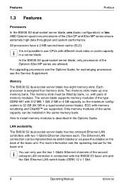
... operating system failure or hardware errors. The flash-EPROM program supplied with independent LAN and COM ports for system analysis, remote configuration and a remote restart even in the event of the server blade. The two redundant hot-pluggable management blades of the PRIMERGY BX600 S2 and BX600 S3 basic unit with the utilities from Fujitsu Technology Solutions allows fast BIOS updating via the USB interface. BX630 S2 Operating Manual 11 User-friendly menus guide you to configure...
... operating system failure or hardware errors. The flash-EPROM program supplied with independent LAN and COM ports for system analysis, remote configuration and a remote restart even in the event of the server blade. The two redundant hot-pluggable management blades of the PRIMERGY BX600 S2 and BX600 S3 basic unit with the utilities from Fujitsu Technology Solutions allows fast BIOS updating via the USB interface. BX630 S2 Operating Manual 11 User-friendly menus guide you to configure...
Operator Manual
Page 24
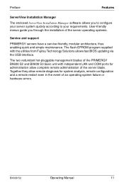
... to install the BX630 S2 dualsocket server blade in the basic unit.The BX630 S2 quad-socket server blade is switched on the configuration, the PRIMERGY BX630 S2 Scalable Server Blade occupies one or two of the ten slots in the PRIMERGY BX600 S2 or BX600 S3 basic unit. You may not switch off . To add a server blade, you must first remove the dummy module from the corresponding slot. 24 Operating Manual BX630 S2 Removing the...
... to install the BX630 S2 dualsocket server blade in the basic unit.The BX630 S2 quad-socket server blade is switched on the configuration, the PRIMERGY BX630 S2 Scalable Server Blade occupies one or two of the ten slots in the PRIMERGY BX600 S2 or BX600 S3 basic unit. You may not switch off . To add a server blade, you must first remove the dummy module from the corresponding slot. 24 Operating Manual BX630 S2 Removing the...
Operator Manual
Page 31
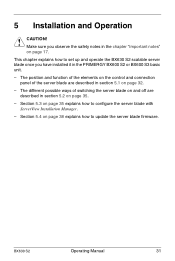
... how to configure the server blade with ServerView Installation Manager. - BX630 S2 Operating Manual 31 Section 5.4 on page 35. - The different possible ways of the server blade are described in the chapter "Important notes" on page 17. The position and function of the elements on the control and connection panel of switching the server blade on and off are described in the PRIMERGY BX600 S2 or...
... how to configure the server blade with ServerView Installation Manager. - BX630 S2 Operating Manual 31 Section 5.4 on page 35. - The different possible ways of the server blade are described in the chapter "Important notes" on page 17. The position and function of the elements on the control and connection panel of switching the server blade on and off are described in the PRIMERGY BX600 S2 or...

Operator Manual
Page 34
... (RAID message) (3Hz) 34 Operating Manual BX630 S2 Control and Connection Panel Installation and Operation 6 NIC indicator (green LED) Dark: System or server blade is off and LAN interface is on page 29) 8 Hard disk access (green LED) Dark: Hard disk drive not active. Glows green: Existing LAN connection. Glows green: Hard disk drive active. 9 Hard disk drive indicator (orange LED) Dark: No error Glows orange: Server blade is not active. Flashes green: Active LAN. 7 USB/VGA connector Connector for adapter cable with two USB ports for external devices (e.g.
... (RAID message) (3Hz) 34 Operating Manual BX630 S2 Control and Connection Panel Installation and Operation 6 NIC indicator (green LED) Dark: System or server blade is off and LAN interface is on page 29) 8 Hard disk access (green LED) Dark: Hard disk drive not active. Glows green: Existing LAN connection. Glows green: Hard disk drive active. 9 Hard disk drive indicator (orange LED) Dark: No error Glows orange: Server blade is not active. Flashes green: Active LAN. 7 USB/VGA connector Connector for adapter cable with two USB ports for external devices (e.g.
Operator Manual
Page 35
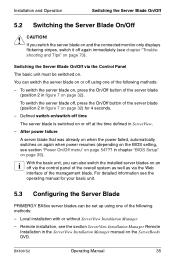
... unit. 5.3 Configuring the Server Blade PRIMERGY BX6xx server blades can also switch the installed server blades on an off at the time defined in chapter "BIOS Setup" on the ServerBooks DVD. After power failure A server blade that was already on when the power failed, automatically switches on again when power resumes (depending on the BIOS setting, see the section ServerView Installation Manager Remote Installation in figure 7 on page 32). Switching the Server Blade On...
... unit. 5.3 Configuring the Server Blade PRIMERGY BX6xx server blades can also switch the installed server blades on an off at the time defined in chapter "BIOS Setup" on the ServerBooks DVD. After power failure A server blade that was already on when the power failed, automatically switches on again when power resumes (depending on the BIOS setting, see the section ServerView Installation Manager Remote Installation in figure 7 on page 32). Switching the Server Blade On...

Operator Manual
Page 36
...-ROM drive and, if required, also the floppy disk drive to the USB ports of the breakout cable (see figure 6 on page 29). Ê Make sure that the basic unit is switched on. Ê To switch the server blade on, press the On/Off button on the control panel (position 2 in figure 7 on the PRIMERGY ServerBooks DVD, which is used by pressing the KVM button. Configuring the Server Blade Installation and Operation...
...-ROM drive and, if required, also the floppy disk drive to the USB ports of the breakout cable (see figure 6 on page 29). Ê Make sure that the basic unit is switched on. Ê To switch the server blade on, press the On/Off button on the control panel (position 2 in figure 7 on the PRIMERGY ServerBooks DVD, which is used by pressing the KVM button. Configuring the Server Blade Installation and Operation...

Operator Manual
Page 37
... booted from the Exit menu. Preparing the Software Booting from the CD-ROM drive Boot the relevant server blade from the ServerView Installation Manager CD to the KVM blade on the control panel of the server blade to switch the keyboard, mouse and the monitor of the KVM blade to call up the BIOS setup of the basic unit. For information see the BX600 S2 or BX600 S3 basic unit operating manual...
... booted from the Exit menu. Preparing the Software Booting from the CD-ROM drive Boot the relevant server blade from the ServerView Installation Manager CD to the KVM blade on the control panel of the server blade to switch the keyboard, mouse and the monitor of the KVM blade to call up the BIOS setup of the basic unit. For information see the BX600 S2 or BX600 S3 basic unit operating manual...
Operator Manual
Page 41
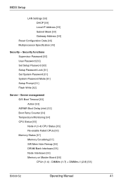
... Address [59] Reset Configuration Data [48] Multiprocessor Specification [49] Security - Security functions Supervisor Password [60] User Password [60] Set Setup Password [60] Setup Password Lock [61] Set System Password [61] System Password Mode [61] Setup Prompt [61] Flash Write [62] Server - Server management O/S Boot Timeout [63] Action [63] ASR&R Boot Delay (min) [63] Boot Retry Counter [64] Temperature Monitoring [64] CPU Status [65] Node # (1-4) CPU Status [65] Re-enable Failed CPUs [66] Memory Status [67] Memory Scrubbing [67] SW...
... Address [59] Reset Configuration Data [48] Multiprocessor Specification [49] Security - Security functions Supervisor Password [60] User Password [60] Set Setup Password [60] Setup Password Lock [61] Set System Password [61] System Password Mode [61] Setup Prompt [61] Flash Write [62] Server - Server management O/S Boot Timeout [63] Action [63] ASR&R Boot Delay (min) [63] Boot Retry Counter [64] Temperature Monitoring [64] CPU Status [65] Node # (1-4) CPU Status [65] Re-enable Failed CPUs [66] Memory Status [67] Memory Scrubbing [67] SW...

Operator Manual
Page 43
... start the operating system, and confirm your entry by pressing Enter. Opening the pop-up boot menu Use this parameter setting, you must enter and confirm the Setup password. The Main menu opens and, if applicable, you can open the Main menu or a pop-up boot menu is displayed. Ê Use the Ê or Ë cursor keys to select the drive from the drive that is marked with Enter. BIOS Setup Entering the BIOS Setup 6.1 Entering the BIOS Setup Ê Start the server...
... start the operating system, and confirm your entry by pressing Enter. Opening the pop-up boot menu Use this parameter setting, you must enter and confirm the Setup password. The Main menu opens and, if applicable, you can open the Main menu or a pop-up boot menu is displayed. Ê Use the Ê or Ë cursor keys to select the drive from the drive that is marked with Enter. BIOS Setup Entering the BIOS Setup 6.1 Entering the BIOS Setup Ê Start the server...

Operator Manual
Page 61
... user password. System Password Mode Defines the effect of the supervisor password. I Requirement: A supervisor password must have been defined. This lock is not prompted to enter a password is opened in which you are using a USB keyboard. Keyboard After the device is started with their own BIOS. Setup Prompt Defines whether the Setup prompt is started , the operating system is displayed during system start (Enabled) or not (Disabled). BIOS Setup Security menu Setup Password Lock Defines the effect of the user password. BX630 S2 Operating Manual...
... user password. System Password Mode Defines the effect of the supervisor password. I Requirement: A supervisor password must have been defined. This lock is not prompted to enter a password is opened in which you are using a USB keyboard. Keyboard After the device is started with their own BIOS. Setup Prompt Defines whether the Setup prompt is started , the operating system is displayed during system start (Enabled) or not (Disabled). BIOS Setup Security menu Setup Password Lock Defines the effect of the user password. BX630 S2 Operating Manual...

Operator Manual
Page 69
.... Defines the transfer speed used for communication with the terminal (Serial # or Disabled). Re-enable Failed DIMMs Resets all memory modules flagged as Failed to Enabled. 6.6.3 Console Redirection Figure 20: Console Redirection menu Port Defines the port used for communication with the terminal. Baud Rate: Requirement: The Port field must be set to Disabled. BX630 S2 Operating Manual 69 BIOS Setup Server menu Enabled If the bank is fitted, the memory module is transferred to...
.... Defines the transfer speed used for communication with the terminal (Serial # or Disabled). Re-enable Failed DIMMs Resets all memory modules flagged as Failed to Enabled. 6.6.3 Console Redirection Figure 20: Console Redirection menu Port Defines the port used for communication with the terminal. Baud Rate: Requirement: The Port field must be set to Disabled. BX630 S2 Operating Manual 69 BIOS Setup Server menu Enabled If the bank is fitted, the memory module is transferred to...

Operator Manual
Page 70
... connection is displayed in keyboard mode. Flow Control Defines how transfer via the port is enabled. Disabled The function is only available during system startup. Standard The terminal connection is disabled. This setting must be set to the server using a direct serial connection (null modem cable). You can display color or only black and white. Mode Defines how long the terminal connection is sent to allocate for example, open and modify the BIOS Setup of video...
... connection is displayed in keyboard mode. Flow Control Defines how transfer via the port is enabled. Disabled The function is only available during system startup. Standard The terminal connection is disabled. This setting must be set to the server using a direct serial connection (null modem cable). You can display color or only black and white. Mode Defines how long the terminal connection is sent to allocate for example, open and modify the BIOS Setup of video...
Operator Manual
Page 75
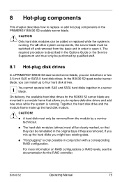
... can be added or replaced while the system is described in a module frame that they are mounted in the Options Guide or the Service Supplement and must be performed by a service technician. ● The hard disk modules (drives) must all other system components, the server blade must only be switched off and removed from the basic unit in conjunction with a corresponding RAID configuration. BX630 S2 Operating Manual 75
... can be added or replaced while the system is described in a module frame that they are mounted in the Options Guide or the Service Supplement and must be performed by a service technician. ● The hard disk modules (drives) must all other system components, the server blade must only be switched off and removed from the basic unit in conjunction with a corresponding RAID configuration. BX630 S2 Operating Manual 75
Operator Manual
Page 83
Abbreviations ASR&R Automatic Server Reconfiguration and Restart ATA Advanced Technology Attachment BIOS Basic Input-Output System CD Compact Disk COM Communication CPU Central Processing Unit DBMS Database Management System DC Dual Core DDR Double Data Rate (RAM) DIMM Dual Inline Memory Module DVD Digital Versatile Disk ECC Error Correcting Code EDC Error Detection Code BX630 S2 Operating Manual 83
Abbreviations ASR&R Automatic Server Reconfiguration and Restart ATA Advanced Technology Attachment BIOS Basic Input-Output System CD Compact Disk COM Communication CPU Central Processing Unit DBMS Database Management System DC Dual Core DDR Double Data Rate (RAM) DIMM Dual Inline Memory Module DVD Digital Versatile Disk ECC Error Correcting Code EDC Error Detection Code BX630 S2 Operating Manual 83

Operator Manual
Page 87
... compatibility 13, 20 electrostatic-sensitive devices (ESD) 19 EMC directive 13 EMC regulations 78, 81 environment class 14 environmental protection 20 Error Correcting Code 10 ESD (electrostatic-sensitive devices) 19 F Fibre Channel 9 firmware 38 update 38 flash-EPROM 11 H hard disk drive acclimatization time 77 dummy module 75 handling 75, 77 install 75 install/remove 79 module frame 75, 79 replacing online 81 BX630 S2 Operating Manual 87
... compatibility 13, 20 electrostatic-sensitive devices (ESD) 19 EMC directive 13 EMC regulations 78, 81 environment class 14 environmental protection 20 Error Correcting Code 10 ESD (electrostatic-sensitive devices) 19 F Fibre Channel 9 firmware 38 update 38 flash-EPROM 11 H hard disk drive acclimatization time 77 dummy module 75 handling 75, 77 install 75 install/remove 79 module frame 75, 79 replacing online 81 BX630 S2 Operating Manual 87