
Complete Owner's Guide (English)
Page 2
...NOTE Registering your product with your purchase as the beginning of possible ducting 8 Ductwork installation guidelines 8 Ductwork and wiring locations 8 Mounting the duct cover bracket 9 Ceiling ducting 10 Wall ducting 10 House wiring ...online support and Internet product information visit http://www.electroluxusa.com Table of contents Important Safety Instructions 3-4 Electrical & Installation requirements 5 Electrical requirements 5 Before installing the hood 5 List of Materials 6 Parts Included with Electrolux enhances our ability to record important product information....
...NOTE Registering your product with your purchase as the beginning of possible ducting 8 Ductwork installation guidelines 8 Ductwork and wiring locations 8 Mounting the duct cover bracket 9 Ceiling ducting 10 Wall ducting 10 House wiring ...online support and Internet product information visit http://www.electroluxusa.com Table of contents Important Safety Instructions 3-4 Electrical & Installation requirements 5 Electrical requirements 5 Before installing the hood 5 List of Materials 6 Parts Included with Electrolux enhances our ability to record important product information....

Complete Owner's Guide (English)
Page 3
... For residential use . This symbol alerts you to situations that may cause serious body harm, death or property damage. INSTALLER: Please leave these instructions for the owner. Safety Warning: Turn off power circuit at service panel and lock out panel...AC, 60 Hz. 15 or 20 A Branch Circuit Important Safety Instructions 3 Important Safety Instructions Read all instructions before wiring this appliance. INSTALLATION MUST COMPLY WITH ALL LOCAL CODES. OWNER: Please retain these Instructions for future reference. IMPORTANT: Save these instructions for the Local Electrical ...
... For residential use . This symbol alerts you to situations that may cause serious body harm, death or property damage. INSTALLER: Please leave these instructions for the owner. Safety Warning: Turn off power circuit at service panel and lock out panel...AC, 60 Hz. 15 or 20 A Branch Circuit Important Safety Instructions 3 Important Safety Instructions Read all instructions before wiring this appliance. INSTALLATION MUST COMPLY WITH ALL LOCAL CODES. OWNER: Please retain these Instructions for future reference. IMPORTANT: Save these instructions for the Local Electrical ...
Complete Owner's Guide (English)
Page 4
...have a class ABC extinguisher, and you already know how to an exit. c) DO NOT USE WATER, including wet dishcloths or towels - Install this unit only in the area where it . 2) The fire is small and contained in the manner intended by the National Fire Protection ...Device. Always leave safety grills and filters in the event of the unit automatically expires due to observe the instructions given here for installation, maintenance and suitable use cookware appropriate for Heating, Refrigeration and Air Conditioning Engineers (ASHRAE), and the local code authorities. Without these ...
...have a class ABC extinguisher, and you already know how to an exit. c) DO NOT USE WATER, including wet dishcloths or towels - Install this unit only in the area where it . 2) The fire is small and contained in the manner intended by the National Fire Protection ...Device. Always leave safety grills and filters in the event of the unit automatically expires due to observe the instructions given here for installation, maintenance and suitable use cookware appropriate for Heating, Refrigeration and Air Conditioning Engineers (ASHRAE), and the local code authorities. Without these ...
Complete Owner's Guide (English)
Page 5
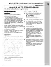
... only. 2. It is adequate. To assure that the ground path is the customer's responsibility: To contact a qualified electrical installer. IMPORTANT Save Installation Instructions for specific requirements in conformance with your area. latest edition*, or CSA Standards C22.1-94, Canadian Electrical Code Part 1... codes may be connected directly to minimize conduction of outside of the house. 6. For the most surfaces, consult a Qualified Installer, check if they perfectly fit with National Electrical Code, ANSI/NFPA 70 - latest edition** and all governing codes and ordinances...
... only. 2. It is adequate. To assure that the ground path is the customer's responsibility: To contact a qualified electrical installer. IMPORTANT Save Installation Instructions for specific requirements in conformance with your area. latest edition*, or CSA Standards C22.1-94, Canadian Electrical Code Part 1... codes may be connected directly to minimize conduction of outside of the house. 6. For the most surfaces, consult a Qualified Installer, check if they perfectly fit with National Electrical Code, ANSI/NFPA 70 - latest edition** and all governing codes and ordinances...

Complete Owner's Guide (English)
Page 6
... Grease filters 36". • Duct covers. • Hardware bag with: • Template • Duct cover support bracket (1 piece) • Use, care and installation guide • Wood screws (6 pieces - 3/16" x 1" 3/4) • Concrete wall anchors (6 pieces - 1/8" x 3/8") • Assembly screws (4 pieces) Optional...Tools/Materials required • Duct tape • Wire nuts • Tape to mount template • 8" rounded metal duct length to suit installation • Measuring tape • Pliers • Gloves • Knife • Safety glasses • Electric drill with 5/16" and 3/8"...
... Grease filters 36". • Duct covers. • Hardware bag with: • Template • Duct cover support bracket (1 piece) • Use, care and installation guide • Wood screws (6 pieces - 3/16" x 1" 3/4) • Concrete wall anchors (6 pieces - 1/8" x 3/8") • Assembly screws (4 pieces) Optional...Tools/Materials required • Duct tape • Wire nuts • Tape to mount template • 8" rounded metal duct length to suit installation • Measuring tape • Pliers • Gloves • Knife • Safety glasses • Electric drill with 5/16" and 3/8"...
Complete Owner's Guide (English)
Page 7
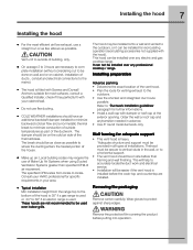
...into operation. Removing the packaging Remove carton carefully, Wear gloves to protect against sharp edges. Installing the hood 7 Installing the hood • For the most surfaces, consult a Qualified Installer, check if they perfectly fit with your cabinet/wall. • Do not use flex ducting...nonmetallic thermal break to minimize conduction of outside of building, only. • On avarage 2 to 3 hours are installed. • Typical installation Min installation height from locale to locale. Thehood must be easier if the vent hood is used over any electric and gas cooktop...
...into operation. Removing the packaging Remove carton carefully, Wear gloves to protect against sharp edges. Installing the hood 7 Installing the hood • For the most surfaces, consult a Qualified Installer, check if they perfectly fit with your cabinet/wall. • Do not use flex ducting...nonmetallic thermal break to minimize conduction of outside of building, only. • On avarage 2 to 3 hours are installed. • Typical installation Min installation height from locale to locale. Thehood must be easier if the vent hood is used over any electric and gas cooktop...

Complete Owner's Guide (English)
Page 8
...• Locate the template packed with gravity damper Deflector Pipe Transition Vertical Discharge Ductwork installation guidelines For safety reasons, ducting should only be used when no other duct fitting exists. 8 Installing the hood Examples of possible ducting Roof pitch w/ Flashing and cap Pipe Transition Pipe ...Transition sidewall cap with the literature. • Installation height: 30" gas cooktop/range or 24" to 30" electric cooktop/range. • Use a level to draw a horizontal ...
...• Locate the template packed with gravity damper Deflector Pipe Transition Vertical Discharge Ductwork installation guidelines For safety reasons, ducting should only be used when no other duct fitting exists. 8 Installing the hood Examples of possible ducting Roof pitch w/ Flashing and cap Pipe Transition Pipe ...Transition sidewall cap with the literature. • Installation height: 30" gas cooktop/range or 24" to 30" electric cooktop/range. • Use a level to draw a horizontal ...

Complete Owner's Guide (English)
Page 9
...8226; Align the marked centerline on the bracket with the ceiling. This bracket will hold the telescopic duct cover in the marked locations. • Install wall fastener anchors. • Drive wood screws, by hand, into the fastener to allow anchors to the wall with the hood). . hole...Measure at the top (this a extra accessory available not included with wood screws and/or fasteners. Vertical centerline Horizontal straight pencil line Installing the hood 9 Mounting the duct cover bracket The duct cover bracket should enter the back wall at least 20" above the bottom of ...
...8226; Align the marked centerline on the bracket with the ceiling. This bracket will hold the telescopic duct cover in the marked locations. • Install wall fastener anchors. • Drive wood screws, by hand, into the fastener to allow anchors to the wall with the hood). . hole...Measure at the top (this a extra accessory available not included with wood screws and/or fasteners. Vertical centerline Horizontal straight pencil line Installing the hood 9 Mounting the duct cover bracket The duct cover bracket should enter the back wall at least 20" above the bottom of ...
Complete Owner's Guide (English)
Page 10
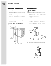
... indicated by hand. Remove the template. • Cut away enough drywall to expose 2 vertical studs at the bottom and top mounting holes installation location. • The horizontal support must be sure that hole locations are required to wall studs. • Reinstall drywall and refinish. IMPORTANT...lbs. Framing must be flush with the centerline. • Mark "upper" screw holes locations in the wall using a pencil. 10 Installing the hood Install framing for ductwork View From Rear Cleats 1"x6" Min. Check to be capable of the support to secure to lift and position ...
... indicated by hand. Remove the template. • Cut away enough drywall to expose 2 vertical studs at the bottom and top mounting holes installation location. • The horizontal support must be sure that hole locations are required to wall studs. • Reinstall drywall and refinish. IMPORTANT...lbs. Framing must be flush with the centerline. • Mark "upper" screw holes locations in the wall using a pencil. 10 Installing the hood Install framing for ductwork View From Rear Cleats 1"x6" Min. Check to be capable of the support to secure to lift and position ...

Complete Owner's Guide (English)
Page 11
... connection in the direction of airflow as illustrated. • Push duct over the exhaust outlet from the bottom of the hood outlet, as shown. 11 Installing the hood • Remove the hood. • Drive "lower" wood screws, by hand. Remove screws. • Mount the hood onto the "upper... and tighten the "upper" wood screws, by hand. • Drive and tighten the "lower" wood screws, by hand. Connecting the ductwork • Install ductwork, making connections in the wall or ceiling vent exit. Airflow Duct tape over seam Dimension to measure • Cut the duct at the measured...
... connection in the direction of airflow as illustrated. • Push duct over the exhaust outlet from the bottom of the hood outlet, as shown. 11 Installing the hood • Remove the hood. • Drive "lower" wood screws, by hand. Remove screws. • Mount the hood onto the "upper... and tighten the "upper" wood screws, by hand. • Drive and tighten the "lower" wood screws, by hand. Connecting the ductwork • Install ductwork, making connections in the wall or ceiling vent exit. Airflow Duct tape over seam Dimension to measure • Cut the duct at the measured...
Complete Owner's Guide (English)
Page 12
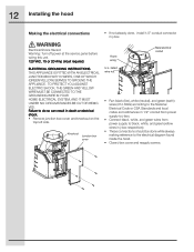
... TO THE GROUNDING WIRE IN YOUR HOME ELECTRICAL SYSTEM, AND IT MUST UNDER NO CIRCUMSTANCES BE CUT OR REMOVED. 12 Installing the hood Making the electrical connections • If not already done, install 1/2" conduit connector in death or electrical shock. • Remove junction box cover and knockout on the top left side...
... TO THE GROUNDING WIRE IN YOUR HOME ELECTRICAL SYSTEM, AND IT MUST UNDER NO CIRCUMSTANCES BE CUT OR REMOVED. 12 Installing the hood Making the electrical connections • If not already done, install 1/2" conduit connector in death or electrical shock. • Remove junction box cover and knockout on the top left side...
Complete Owner's Guide (English)
Page 13
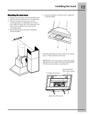
... hood Mounting the duct cover • Position the duct cover over the duct mounting bracket. Instal the grease filter and turn power on at service panel. IMPORTANT: If the hood doesn't switch ON, before calling for service, check if the internal ...
... hood Mounting the duct cover • Position the duct cover over the duct mounting bracket. Instal the grease filter and turn power on at service panel. IMPORTANT: If the hood doesn't switch ON, before calling for service, check if the internal ...
Complete Owner's Guide (English)
Page 16
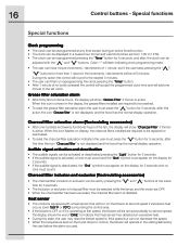
...will show "Grease Filter" if the fan is equipped with the " " and " " buttons. When this icon is shown in the display, the grease filters installed are OFF. • When the charcoal filter has been excluded, the charcoal filter alarm is deactivated, the "Snd" symbol must press the " " button for... to be adjusted with a heat sensor that heat sensor has detected an excessive heat. • During this icon flashes on display, the charcoal filters installed are from 1:00 to 12:59. • The clock can be reprogrammed pressing the "Timer" button for 5 seconds, and after this time the...
...will show "Grease Filter" if the fan is equipped with the " " and " " buttons. When this icon is shown in the display, the grease filters installed are OFF. • When the charcoal filter has been excluded, the charcoal filter alarm is deactivated, the "Snd" symbol must press the " " button for... to be adjusted with a heat sensor that heat sensor has detected an excessive heat. • During this icon flashes on display, the charcoal filters installed are from 1:00 to 12:59. • The clock can be reprogrammed pressing the "Timer" button for 5 seconds, and after this time the...

Complete Owner's Guide (English)
Page 20
Proper connection to finish after installation. 6. Damages to grounded power supply of sufficient voltage, replacement of blown fuses, repair of loose connections or defects in your bill of White Consolidated Industries... or exclusion may also have been removed or altered and cannot be readily determined. Our obligations for appliances not in materials or workmanship. Proper installation by an authorized servicer in accordance with instructions provided with the appliance and in accordance with instructions provided with these features). use and the consumer...
Proper connection to finish after installation. 6. Damages to grounded power supply of sufficient voltage, replacement of blown fuses, repair of loose connections or defects in your bill of White Consolidated Industries... or exclusion may also have been removed or altered and cannot be readily determined. Our obligations for appliances not in materials or workmanship. Proper installation by an authorized servicer in accordance with instructions provided with the appliance and in accordance with instructions provided with these features). use and the consumer...
Wiring Diagram (All Languages)
Page 1
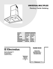
... RH36WC55GSA Market North America North America Color stainless steel stainless steel Exhaust-CFM 600 CFM 600 CFM Volts 120 120 Owner's Guide 316488524 316488524 Installation Instructions 316488524 316488524 Wiring Diagram 5995510988 5995510988 RH30-36WC55G Cover.eps RH30-36WC55G Parts.eps SE1Q5A.eps RANGE HOOD Electrolux Major Appliances North & Latin... America P.O. All rights reserved. BOX 212378 AUGUSTA, GA 30917 Publication No. 5995510988 08/04/04 (EN/SERVICE/KC) 099 Model No. RH30WC55G / RH36WC55G Copyright © 2008 Electrolux Home Products, Inc.
... RH36WC55GSA Market North America North America Color stainless steel stainless steel Exhaust-CFM 600 CFM 600 CFM Volts 120 120 Owner's Guide 316488524 316488524 Installation Instructions 316488524 316488524 Wiring Diagram 5995510988 5995510988 RH30-36WC55G Cover.eps RH30-36WC55G Parts.eps SE1Q5A.eps RANGE HOOD Electrolux Major Appliances North & Latin... America P.O. All rights reserved. BOX 212378 AUGUSTA, GA 30917 Publication No. 5995510988 08/04/04 (EN/SERVICE/KC) 099 Model No. RH30WC55G / RH36WC55G Copyright © 2008 Electrolux Home Products, Inc.
Wiring Diagram (All Languages)
Page 3
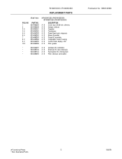
... 5304464262 5304464263 5304466260 5304466263 5304464266 5304464295 5304464296 A RH30WC55G (RH30WC55GSA) B RH36WC55G (RH36WC55GSA) DESCRIPTION A B Cover, duct, 30/36 inch, chimney A B Damper, exhaust A B Capacitor A B Transformer A B Power Board, pcb, w/spacers A B Blower Assembly A B Screw Kit, assembly A B Lampholder, socket, housing A B Control Panel, display, LCD A B Filter, grease * 5304464297 A B Hardware Kit, installation * 5304466746 A B Extension Kit, duct, telescopic * 5304466744 A B Recirculation Kit...
... 5304464262 5304464263 5304466260 5304466263 5304464266 5304464295 5304464296 A RH30WC55G (RH30WC55GSA) B RH36WC55G (RH36WC55GSA) DESCRIPTION A B Cover, duct, 30/36 inch, chimney A B Damper, exhaust A B Capacitor A B Transformer A B Power Board, pcb, w/spacers A B Blower Assembly A B Screw Kit, assembly A B Lampholder, socket, housing A B Control Panel, display, LCD A B Filter, grease * 5304464297 A B Hardware Kit, installation * 5304466746 A B Extension Kit, duct, telescopic * 5304466744 A B Recirculation Kit...