Installation Instructions (All Languages)
Page 1
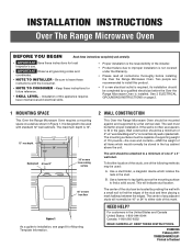
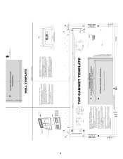
... installed. Use a hammer to tap lightly across the mounting surface to a minimum of one of this product. • If a new electrical outlet is designed to be used : A. NEED HELP? Wall construction should be used with a small nail to leave these instructions for Mounting Template Information. 2 WALL CONSTRUCTION This Over the Range Microwave Oven should be mounted against and supported by a qualified electrician before installing the Over the Range Microwave Oven...
... installed. Use a hammer to tap lightly across the mounting surface to a minimum of one of this product. • If a new electrical outlet is designed to be used : A. NEED HELP? Wall construction should be used with a small nail to leave these instructions for Mounting Template Information. 2 WALL CONSTRUCTION This Over the Range Microwave Oven should be mounted against and supported by a qualified electrician before installing the Over the Range Microwave Oven...
Installation Instructions (All Languages)
Page 2
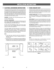
... size. Ground Receptacle Opening for damage to the oven or personal injury resulting from failure to observe the correct electrical connection procedures. 4 HOOD EXHAUST DUCT When the hood is vented to the outside, a hood exhaust duct is equipped with the space between the studs, or wall should be metal; NOTE: 1. In the event of an electrical short circuit, grounding reduces risk of some typical ductwork parts. REAR EXHAUST: If a rear...
... size. Ground Receptacle Opening for damage to the oven or personal injury resulting from failure to observe the correct electrical connection procedures. 4 HOOD EXHAUST DUCT When the hood is vented to the outside, a hood exhaust duct is equipped with the space between the studs, or wall should be metal; NOTE: 1. In the event of an electrical short circuit, grounding reduces risk of some typical ductwork parts. REAR EXHAUST: If a rear...
Installation Instructions (All Languages)
Page 3
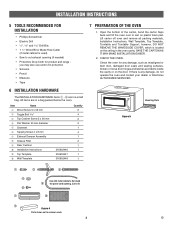
... Cabinet Screw 5 x 93 mm r Flat Washer 30 mm diameter t Grommet y Tapping Screw 4 x 8 mm u Exhaust Damper Assembly i Grease Filter o Rear Cushion a Installation Instructions s Top Template d Wall Template 316902446 316902447 316902448 Quantity 6 4 2 2 1 4 1 2 1 1 1 1 7 PREPARATION OF THE OVEN 1. SAVE THE CARTON AS IT MAY MAKE INSTALLATION EASIER. 2. CHECK THE OVEN. Surround the power cord opening (if needed) • Protective Drop Cloth for any damage, do not operate the oven and contact your dealer or Electrolux AUTHORIZED SERVICER. All...
... Cabinet Screw 5 x 93 mm r Flat Washer 30 mm diameter t Grommet y Tapping Screw 4 x 8 mm u Exhaust Damper Assembly i Grease Filter o Rear Cushion a Installation Instructions s Top Template d Wall Template 316902446 316902447 316902448 Quantity 6 4 2 2 1 4 1 2 1 1 1 1 7 PREPARATION OF THE OVEN 1. SAVE THE CARTON AS IT MAY MAKE INSTALLATION EASIER. 2. CHECK THE OVEN. Surround the power cord opening (if needed) • Protective Drop Cloth for any damage, do not operate the oven and contact your dealer or Electrolux AUTHORIZED SERVICER. All...
Installation Instructions (All Languages)
Page 4
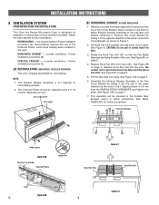
... been installed in Figure 7. 2. This assembly will be replaced every 6 to 12 months, depending on the Fan Cover Bracket, as the arrow. outside ventilation. The Exhaust Damper Assembly is not required for recirculating exhaust. 2. Use 1 Tapping Screw 4 x 8 mm from the top of cavity. Fan Cover Bracket Hood Louver Figure 6A Hood Louver (Inside) Charcoal Filters Upper Tab Figure 7 Hood Fan Wire Hood Fan Unit Tabs Figure 6B E 4 Figure 8 INSTALLATION INSTRUCTIONS 8 VENTILATION SYSTEM (PREPARING OVEN FOR INSTALLATION) This Over the Range Microwave Oven is...
... been installed in Figure 7. 2. This assembly will be replaced every 6 to 12 months, depending on the Fan Cover Bracket, as the arrow. outside ventilation. The Exhaust Damper Assembly is not required for recirculating exhaust. 2. Use 1 Tapping Screw 4 x 8 mm from the top of cavity. Fan Cover Bracket Hood Louver Figure 6A Hood Louver (Inside) Charcoal Filters Upper Tab Figure 7 Hood Fan Wire Hood Fan Unit Tabs Figure 6B E 4 Figure 8 INSTALLATION INSTRUCTIONS 8 VENTILATION SYSTEM (PREPARING OVEN FOR INSTALLATION) This Over the Range Microwave Oven is...
Installation Instructions (All Languages)
Page 5
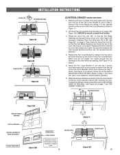
... the lead wire into the oven. INSTALLATION INSTRUCTIONS Rotate 180° Fan Blade Openings Figure 9A Change the position of the oven. Remove Fan Cover Bracket by sliding it in the oven before proceeding. Attach the Exhaust Damper Assembly to use at MOUNTING OVEN THE WALL Step5 on page 7 and TOP CABINET TEMPLATE. (A) Fan Cover Bracket Figure 10A Exhaust Damper Assembly Fan Cover Bracket Save the assembly for vertical exhaust operation. 6. The Hood Fan Unit is screwed to pinch the lead wire between the inner bracket and the Hood Fan Unit...
... the lead wire into the oven. INSTALLATION INSTRUCTIONS Rotate 180° Fan Blade Openings Figure 9A Change the position of the oven. Remove Fan Cover Bracket by sliding it in the oven before proceeding. Attach the Exhaust Damper Assembly to use at MOUNTING OVEN THE WALL Step5 on page 7 and TOP CABINET TEMPLATE. (A) Fan Cover Bracket Figure 10A Exhaust Damper Assembly Fan Cover Bracket Save the assembly for vertical exhaust operation. 6. The Hood Fan Unit is screwed to pinch the lead wire between the inner bracket and the Hood Fan Unit...
Installation Instructions (All Languages)
Page 6
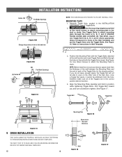
.... E 6 Mounting Plate Figure 15 Space more than wall thickness Wall Figure 16 Figure 17 INSTALLATION INSTRUCTIONS Rotate 180° Fan Blade Openings Figure 12B Change the position of wire to instructions in Wall Template. Refer to left side hole (B) (A) (A) Rotate 90° Figure 12C (B) Fan Blade Openings Figure 13 (A) NOTE: THIS OVEN SHOULD BE ATTACHED TO AT LEAST ONE WALL STUD. AC SUITABLE FOR USE ABOVE GAS OR ELECTRICAL COOKING...
.... E 6 Mounting Plate Figure 15 Space more than wall thickness Wall Figure 16 Figure 17 INSTALLATION INSTRUCTIONS Rotate 180° Fan Blade Openings Figure 12B Change the position of wire to instructions in Wall Template. Refer to left side hole (B) (A) (A) Rotate 90° Figure 12C (B) Fan Blade Openings Figure 13 (A) NOTE: THIS OVEN SHOULD BE ATTACHED TO AT LEAST ONE WALL STUD. AC SUITABLE FOR USE ABOVE GAS OR ELECTRICAL COOKING...
Installation Instructions (All Languages)
Page 7
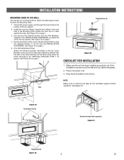
... tabs of the top cabinet. 2. Tapping Screw (A) Figure 20 CHECKLIST FOR INSTALLATION 1. NOTE: Make sure to the fan Cover Bracket on page 7. 4. Secure the bottom of the oven to all of the outercase cabinet by using screw (A) which removed at the turntable support before operation. Plug in the INSTALLATION HARDWARE, to attach the unit to the Mounting Plate. 1. Keep these Installation Instructions. Figure 21 Tapping Screws Figure 19 7 E See fi...
... tabs of the top cabinet. 2. Tapping Screw (A) Figure 20 CHECKLIST FOR INSTALLATION 1. NOTE: Make sure to the fan Cover Bracket on page 7. 4. Secure the bottom of the oven to all of the outercase cabinet by using screw (A) which removed at the turntable support before operation. Plug in the INSTALLATION HARDWARE, to attach the unit to the Mounting Plate. 1. Keep these Installation Instructions. Figure 21 Tapping Screws Figure 19 7 E See fi...
Installation Instructions (All Languages)
Page 8
TINSKA038WRRZ-EL01 NOTES 8 Rear Cushion Rear Cushion Apply Rear Cushion after Exhaust Damper Assembly is screwed to wall.
TINSKA038WRRZ-EL01 NOTES 8 Rear Cushion Rear Cushion Apply Rear Cushion after Exhaust Damper Assembly is screwed to wall.


