Complete Owner's Guide
Page 2
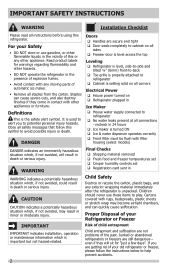
...; Ice & water dispenser operates correctly Front filter must be flush with any moving parts of explosive fumes. • Avoid contact with filter housing (select models) DANGER indicates an imminently hazardous situation which , if not avoided, may become airtight chambers, and can cause severe cuts, and also destroy finishes if they...
...; Ice & water dispenser operates correctly Front filter must be flush with any moving parts of explosive fumes. • Avoid contact with filter housing (select models) DANGER indicates an imminently hazardous situation which , if not avoided, may become airtight chambers, and can cause severe cuts, and also destroy finishes if they...
Complete Owner's Guide
Page 4
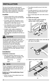
...front-to-back (to ensure that is level and strong enough to support a fully loaded refrigerator. • Consider water supply availability for models equipped with the door hinge side against a wall, you do not hook up water to the refrigerator, remember to turn the ice maker...• All four corners of your refrigerator. To install the toe grille: 1. Do Not block the toe grille on left side of your model. Installation Installation clearances • Allow the following clearances for ease of installation, proper air circulation, and plumbing and electrical connections: Sides & Top...
...front-to-back (to ensure that is level and strong enough to support a fully loaded refrigerator. • Consider water supply availability for models equipped with the door hinge side against a wall, you do not hook up water to the refrigerator, remember to turn the ice maker...• All four corners of your refrigerator. To install the toe grille: 1. Do Not block the toe grille on left side of your model. Installation Installation clearances • Allow the following clearances for ease of installation, proper air circulation, and plumbing and electrical connections: Sides & Top...
Complete Owner's Guide
Page 5
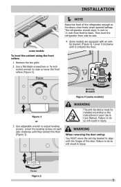
...bracket (Figure 4). WARNING The anti-tip device must be installed according to raise or lower the front rollers (Figure 2). Raise Figure 3 5 INSTALLATION some models) Figure 2 or 3 Use adjustable wrench to -back. Lower it contacts the floor. Failure to do so will result in injury. Failure to do so...from front-to adjust leveling screws. WARNING When reversing the door swing: You MUST move the anti-tip bracket to -side. 4 Some models are equipped with the hinges of the refrigerator enough so the doors close freely when opened halfway. The refrigerator should slope ¼ inch ...
...bracket (Figure 4). WARNING The anti-tip device must be installed according to raise or lower the front rollers (Figure 2). Raise Figure 3 5 INSTALLATION some models) Figure 2 or 3 Use adjustable wrench to -back. Lower it contacts the floor. Failure to do so will result in injury. Failure to do so...from front-to adjust leveling screws. WARNING When reversing the door swing: You MUST move the anti-tip bracket to -side. 4 Some models are equipped with the hinges of the refrigerator enough so the doors close freely when opened halfway. The refrigerator should slope ¼ inch ...
Complete Owner's Guide
Page 7
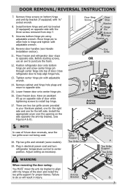
.... 12. Before starting screws, use an awl to opposite side. There are two toe grille covers provided in injury. Flip toe grille and reinstall (some models). 19. DOOR REMOVAL/REVERSAL INSTRUCTIONS 7. one for the right side and one for proper blance. Failure to opposite side. 15. Door Stop Screw Door Stop...
.... 12. Before starting screws, use an awl to opposite side. There are two toe grille covers provided in injury. Flip toe grille and reinstall (some models). 19. DOOR REMOVAL/REVERSAL INSTRUCTIONS 7. one for the right side and one for proper blance. Failure to opposite side. 15. Door Stop Screw Door Stop...

Complete Owner's Guide
Page 8
... Install the two screws into the top of handles, please review these handles. IMPORTANT To ensure proper installation of the handle. 3. Your model will have either a right hand or left hand door swing. Place rounded part of handle onto shoulder screw on face of door and align... top of the handle until the handle is flush with the door, then tighten another ½ turn . Screw Screw Handle Stainless Steel Models Screw Handle Shoulder Screw Handle Shoulder Screw Button Plug Set Screw To attach metal freezer handle: 1. Place rounded part of handle onto shoulder screw...
... Install the two screws into the top of handles, please review these handles. IMPORTANT To ensure proper installation of the handle. 3. Your model will have either a right hand or left hand door swing. Place rounded part of handle onto shoulder screw on face of door and align... top of the handle until the handle is flush with the door, then tighten another ½ turn . Screw Screw Handle Stainless Steel Models Screw Handle Shoulder Screw Handle Shoulder Screw Button Plug Set Screw To attach metal freezer handle: 1. Place rounded part of handle onto shoulder screw...
Complete Owner's Guide
Page 12
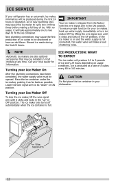
... valve will produce 2.5 to fill the ice container. ICE SERVICE If your refrigerator has an automatic ice maker, minimal ice will be installed in most models at a rate of 8 cubes every 80 to its "down" or ON position. Lower the wire signal arm to 160 minutes. CAUTION Do Not place the...
... valve will produce 2.5 to fill the ice container. ICE SERVICE If your refrigerator has an automatic ice maker, minimal ice will be installed in most models at a rate of 8 cubes every 80 to its "down" or ON position. Lower the wire signal arm to 160 minutes. CAUTION Do Not place the...
Complete Owner's Guide
Page 13
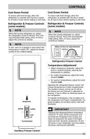
... the coldest setting. NOTE When first turning refrigerator on , adjust the refrigerator control to the refrigerator. Refrigerator & Freezer Controls Refrigerator & Freezer Controls (some models) (some models) NOTE When first turning refrigerator on , adjust control to Normal. This is the recommended initial setting. After 24 hours, adjust the controls as needed...
... the coldest setting. NOTE When first turning refrigerator on , adjust the refrigerator control to the refrigerator. Refrigerator & Freezer Controls Refrigerator & Freezer Controls (some models) (some models) NOTE When first turning refrigerator on , adjust control to Normal. This is the recommended initial setting. After 24 hours, adjust the controls as needed...

Complete Owner's Guide
Page 17
... a soft cloth. Rinse and dry. CARE & CLEANING Part Interior & Door Liners Door Gaskets Drawers & Bins Glass Shelves Toe Grille Exterior & Handles Exterior & Handles (Stainless Steel Models Only) Replacing Light Bulbs Care & Cleaning Tips What To Use Tips and Precautions • Soap and water • Baking soda and water Use 2 tablespoons of...
... a soft cloth. Rinse and dry. CARE & CLEANING Part Interior & Door Liners Door Gaskets Drawers & Bins Glass Shelves Toe Grille Exterior & Handles Exterior & Handles (Stainless Steel Models Only) Replacing Light Bulbs Care & Cleaning Tips What To Use Tips and Precautions • Soap and water • Baking soda and water Use 2 tablespoons of...
Complete Owner's Guide
Page 18
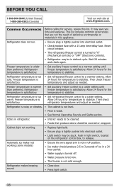
...controls) or "OFF" (Electronic controls). • Refrigerator may be stuck. Freezer temperature is colder than preferred. Cabinet light not working (some models) • Ensure the wire signal arm is tightly pushed into electrical outlet. • Check/replace fuse with a 15 amp time-delay fuse... is satisfactory. BEFORE YOU CALL 1-800-944-9044 (United States) 1-800-265-8352 (Canada) Visit our web site at www.frigidaire.com. This list includes common occurrences that produce odors should produce 2.5 to 3 pounds of defective workmanship or materials in light switch,...
...controls) or "OFF" (Electronic controls). • Refrigerator may be stuck. Freezer temperature is colder than preferred. Cabinet light not working (some models) • Ensure the wire signal arm is tightly pushed into electrical outlet. • Check/replace fuse with a 15 amp time-delay fuse... is satisfactory. BEFORE YOU CALL 1-800-944-9044 (United States) 1-800-265-8352 (Canada) Visit our web site at www.frigidaire.com. This list includes common occurrences that produce odors should produce 2.5 to 3 pounds of defective workmanship or materials in light switch,...
Installation Instructions
Page 1
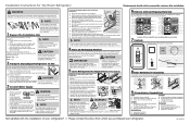
...be sure to check for leaks again in 24 hours. 4 Place In Permanent Position If possible, use a self-piercing shut-off valve for your model. 7 Controls When changing controls, wait 24 hours before making additional adjustments. When using the front rollers: 1 Remove the toe grille (Figure 1). ... Cabinet is turned ON. The refrigerator should slope ¼ inch to the instructions in injury. Anti-tip Bracket Figure 4 (some models) 4 Some models are provided only as a possible customer option. CAUTION Room temperatures below 55°F (13°C) or above 110°F (43°C) ...
...be sure to check for leaks again in 24 hours. 4 Place In Permanent Position If possible, use a self-piercing shut-off valve for your model. 7 Controls When changing controls, wait 24 hours before making additional adjustments. When using the front rollers: 1 Remove the toe grille (Figure 1). ... Cabinet is turned ON. The refrigerator should slope ¼ inch to the instructions in injury. Anti-tip Bracket Figure 4 (some models) 4 Some models are provided only as a possible customer option. CAUTION Room temperatures below 55°F (13°C) or above 110°F (43°C) ...
Wiring Diagram
Page 2
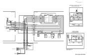
... LT.BLUE GRY/YEL RED RED GRY/YEL LT.BLUE LT.BLUE LT.BLUE YEL LT.BLUE GRN/YEL RED NOTE DENOTES NOT ON ALL MODELS. STARTER WITH RUN CAPACITOR START 6 S S RUN 5 C M M 3 2 L1 OVERLOAD COMR MOTOR PTC STARTER RUN CAPACITOR * CAPACITOR IS ONLY USED WITH SOME P.T.C. BLUE DEFROST BI-METAL COIL... PORKCHOP SPLICE SPLICE LT.BLUE LT.BLUE RED BLACK BROWN YEL/BLK RED/WHITE SERVICE CORD SEE COMPRESSOR WIRING CONDENSER FAN I /M WATER VALVE COMPRESSOR WIRING P.T.C. MODELS. Wire Diagram A01475501 FREEZER COMPARTMENT EVAPORATOR FAN COIL COVER ICE MAKER RED/WHITE GRN/YEL LT.
... LT.BLUE GRY/YEL RED RED GRY/YEL LT.BLUE LT.BLUE LT.BLUE YEL LT.BLUE GRN/YEL RED NOTE DENOTES NOT ON ALL MODELS. STARTER WITH RUN CAPACITOR START 6 S S RUN 5 C M M 3 2 L1 OVERLOAD COMR MOTOR PTC STARTER RUN CAPACITOR * CAPACITOR IS ONLY USED WITH SOME P.T.C. BLUE DEFROST BI-METAL COIL... PORKCHOP SPLICE SPLICE LT.BLUE LT.BLUE RED BLACK BROWN YEL/BLK RED/WHITE SERVICE CORD SEE COMPRESSOR WIRING CONDENSER FAN I /M WATER VALVE COMPRESSOR WIRING P.T.C. MODELS. Wire Diagram A01475501 FREEZER COMPARTMENT EVAPORATOR FAN COIL COVER ICE MAKER RED/WHITE GRN/YEL LT.

Energy Guide
Page 1
l Cost range based only on models of similar capacity with yellow numbers are based on the same test procedures. Estimated Yearly Energy Cost $ 52 Cost range not available X4X3X0 kWh Estimated ...
l Cost range based only on models of similar capacity with yellow numbers are based on the same test procedures. Estimated Yearly Energy Cost $ 52 Cost range not available X4X3X0 kWh Estimated ...


