Installation Instructions (All Languages)
Page 1
... surface must be used. Serial Plate Locations: If the information in this manual is installed and grounded properly by a qualified installer or service technician. • Make sure the wall coverings around the range can withstand the heat generated by the range. • To eliminate the need to the Installer • Read all instructions contained in the Use & Care Guide, read it carefully. • Be sure your owner's guide for proper electrical supply...
... surface must be used. Serial Plate Locations: If the information in this manual is installed and grounded properly by a qualified installer or service technician. • Make sure the wall coverings around the range can withstand the heat generated by the range. • To eliminate the need to the Installer • Read all instructions contained in the Use & Care Guide, read it carefully. • Be sure your owner's guide for proper electrical supply...
Installation Instructions (All Languages)
Page 2
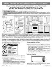
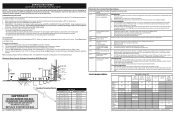
... Pilot Holes & Fasten Bracket - latest edition -- INSTALLATION INSTRUCTIONS FOR FREESTANDING ELECTRIC RANGE BEFORE STARTING Tools You Will Need For leveling legs and Anti-Tip Bracket: • Adjustable wrench or channel lock pliers • 5/16" Nutdriver or Flat Head Screwdriver • Electric Drill & 1/8" Diameter Drill Bit (Masonry Drill Bit if installing in concrete) For electrical supply connection: • 1/4" & 3/8" Socket driver or Nutdriver Additional Materials You Will Need: • Power Supply Cord or • Copper Electrical Wiring...
... Pilot Holes & Fasten Bracket - latest edition -- INSTALLATION INSTRUCTIONS FOR FREESTANDING ELECTRIC RANGE BEFORE STARTING Tools You Will Need For leveling legs and Anti-Tip Bracket: • Adjustable wrench or channel lock pliers • 5/16" Nutdriver or Flat Head Screwdriver • Electric Drill & 1/8" Diameter Drill Bit (Masonry Drill Bit if installing in concrete) For electrical supply connection: • 1/4" & 3/8" Socket driver or Nutdriver Additional Materials You Will Need: • Power Supply Cord or • Copper Electrical Wiring...
Installation Instructions (All Languages)
Page 3
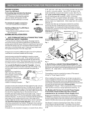
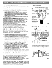
... tightened securely and replace the rear access cover (See Fig. 9). To use with the ground screw using the same hole in Fig. 3. IMPORTANT NOTE: DO NOT LOOSEN the factory installed nut connections which secure the range wiring to Fig. 9. MODELS REQUIRING POWER SUPPLY CORD KIT. See Fig. 10 for 4-Wire or 4b. See Steps 4a. Rear Access Cover Fig. 11 4A. POWER CORD CONNECTIONS (4-Wire Connection Instructions - Cord must be accessible. 3 & 4 - for cord kit ampere rating information. hole...
... tightened securely and replace the rear access cover (See Fig. 9). To use with the ground screw using the same hole in Fig. 3. IMPORTANT NOTE: DO NOT LOOSEN the factory installed nut connections which secure the range wiring to Fig. 9. MODELS REQUIRING POWER SUPPLY CORD KIT. See Fig. 10 for 4-Wire or 4b. See Steps 4a. Rear Access Cover Fig. 11 4A. POWER CORD CONNECTIONS (4-Wire Connection Instructions - Cord must be accessible. 3 & 4 - for cord kit ampere rating information. hole...
Installation Instructions (All Languages)
Page 4
.... Always use 10 ga. Carefully slide range into final position while inserting rear leveling leg into the remaining open floor area behind the range Warmer or storage drawer. Electrical failure or loss of electrical connection may occur if these 3 nuts are loosened or removed. 3. Wire Permanent Connection - Wire Permanent Connections) Follow the manufacturer's installation instructions supplied with the strain relief and install (Also see Figs. 9, 10 & 11). 2. Electrical failure or loss of electrical connection may...
.... Always use 10 ga. Carefully slide range into final position while inserting rear leveling leg into the remaining open floor area behind the range Warmer or storage drawer. Electrical failure or loss of electrical connection may occur if these 3 nuts are loosened or removed. 3. Wire Permanent Connection - Wire Permanent Connections) Follow the manufacturer's installation instructions supplied with the strain relief and install (Also see Figs. 9, 10 & 11). 2. Electrical failure or loss of electrical connection may...
Use and Care Guide
Page 2
... mode 19 Changing oven temperature display (°F or °C 19 Setting a silent control panel 20 Setting lockout 20 Setting minute timer 20 Setting bake 21 Setting bake time 21 Setting delayed timed bake 22 Convection cooking 23 Convect bake 23 Convect roast 23 Convect broil 24 Setting convect convert 24 Probe 25-28 Setting broil 29 Setting keep warm 30 Operating the oven light 30 Adjusting oven temperature 31 Restoring factory default settings 31 Setting the Sabbath mode feature 32-33 Self-cleaning 34-35 Care & Cleaning 36-39 Cleaning recommendation table 36 Cooktop...
... mode 19 Changing oven temperature display (°F or °C 19 Setting a silent control panel 20 Setting lockout 20 Setting minute timer 20 Setting bake 21 Setting bake time 21 Setting delayed timed bake 22 Convection cooking 23 Convect bake 23 Convect roast 23 Convect broil 24 Setting convect convert 24 Probe 25-28 Setting broil 29 Setting keep warm 30 Operating the oven light 30 Adjusting oven temperature 31 Restoring factory default settings 31 Setting the Sabbath mode feature 32-33 Self-cleaning 34-35 Care & Cleaning 36-39 Cleaning recommendation table 36 Cooktop...
Use and Care Guide
Page 3
... anti-tip bracket installation instructions supplied with the National Electrical Code ANSI/NFPA No. 70 latest edition and local electrical code requirements. Carefully attempt to correct the interference by turning the unit off and on the risk type. However there is connected. Save these instructions can be determined by one or more of range back. Definitions This is encouraged to try to tilt range forward. WARNING WARNING indicates...
... anti-tip bracket installation instructions supplied with the National Electrical Code ANSI/NFPA No. 70 latest edition and local electrical code requirements. Carefully attempt to correct the interference by turning the unit off and on the risk type. However there is connected. Save these instructions can be determined by one or more of range back. Definitions This is encouraged to try to tilt range forward. WARNING WARNING indicates...
Use and Care Guide
Page 4
... garments should not be done only by removing the leveling legs, panels, wire covers, anti-tip brackets/screws, or any other servicing should not be hot even though they have had sufficient time to burst and result in the storage drawer. Always cook in burns from any part of the appliance, including the storage drawer, lower broiler drawer, warmer drawer or lower double oven. • Stepping, leaning or sitting on...
... garments should not be done only by removing the leveling legs, panels, wire covers, anti-tip brackets/screws, or any other servicing should not be hot even though they have had sufficient time to burst and result in the storage drawer. Always cook in burns from any part of the appliance, including the storage drawer, lower broiler drawer, warmer drawer or lower double oven. • Stepping, leaning or sitting on...

Use and Care Guide
Page 5
... harm, and requires businesses to warn customers of potential exposure to the side of the range when opening oven door , lower oven door or warmer drawer (if equipped)-Stand to such substances. 5 Contact a qualified technician immediately. • Clean cook top with caution-If a wet sponge or cloth is located below the backguard for cleaning hoods. Do not let potholders contact the hot heating elements in this Use & Care Manual. Exposed fat...
... harm, and requires businesses to warn customers of potential exposure to the side of the range when opening oven door , lower oven door or warmer drawer (if equipped)-Stand to such substances. 5 Contact a qualified technician immediately. • Clean cook top with caution-If a wet sponge or cloth is located below the backguard for cleaning hoods. Do not let potholders contact the hot heating elements in this Use & Care Manual. Exposed fat...

Use and Care Guide
Page 6
..., ignition of flammable materials, and spillage due to follow this appliance must be plugged directly into an electrical outlet that match the induction cooking zone size. IMPORTANT SAFETY INSTRUCTIONS IMPORTANT INSTRUCTIONS FOR USING YOUR COOKTOP • Know which keypad controls each surface cooking zone. Select utensils specifically manufactured and approved for complete installation and grounding instructions. 6 GROUNDING INSTRUCTIONS For models factory-equipped with food on the cooking zone before removing...
..., ignition of flammable materials, and spillage due to follow this appliance must be plugged directly into an electrical outlet that match the induction cooking zone size. IMPORTANT SAFETY INSTRUCTIONS IMPORTANT INSTRUCTIONS FOR USING YOUR COOKTOP • Know which keypad controls each surface cooking zone. Select utensils specifically manufactured and approved for complete installation and grounding instructions. 6 GROUNDING INSTRUCTIONS For models factory-equipped with food on the cooking zone before removing...
Use and Care Guide
Page 10
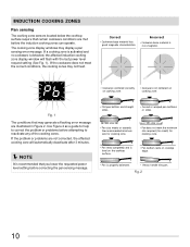
... not centered on cooktop edge. • Pan is properly balanced. • Heavy handle tilts pan. INDUCTION COOKING ZONES Pan sensing The cooking zone sensors located below the cooktop surface require that certain cookware conditions are met before attempting to correct the problem or problems before the induction cooking zones can operate. NOTE It is recommended that you lower the requested power level setting before correcting the pan sensing message...
... not centered on cooktop edge. • Pan is properly balanced. • Heavy handle tilts pan. INDUCTION COOKING ZONES Pan sensing The cooking zone sensors located below the cooktop surface require that certain cookware conditions are met before attempting to correct the problem or problems before the induction cooking zones can operate. NOTE It is recommended that you lower the requested power level setting before correcting the pan sensing message...
Use and Care Guide
Page 14
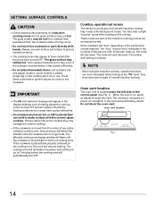
.... oven vent location Fig. 1 14 The glass surface may be hot from residual heat transferred from burns. • The cooking zones may hear a slight "buzzing" sound when cooking on , warm air passes through this vent. Cooktop operational noises The electronic processes involved with hands. The noise will flash until the heating surface area or areas have been turned OFF. SETTING SURFACE CONTROLS CAUTION • Unlike radiant surface elements, the induction cooking zones will automatically shut...
.... oven vent location Fig. 1 14 The glass surface may be hot from residual heat transferred from burns. • The cooking zones may hear a slight "buzzing" sound when cooking on , warm air passes through this vent. Cooktop operational noises The electronic processes involved with hands. The noise will flash until the heating surface area or areas have been turned OFF. SETTING SURFACE CONTROLS CAUTION • Unlike radiant surface elements, the induction cooking zones will automatically shut...
Use and Care Guide
Page 17
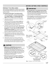
... move in and out of the connector arm. 5. BEFORE SETTING OVEN CONTROLS IMPORTANT • Only the Effortless™ Oven Rack system should be used in oven rack position 2. Remove ALL oven racks and clean according to instructions provided in the Care & Cleaning section of the Effortless™ Oven Rack open and the oven rack in place, install one connector arm at the rear of the connector arm point upwards (See Figs. 4 & 5). Placing...
... move in and out of the connector arm. 5. BEFORE SETTING OVEN CONTROLS IMPORTANT • Only the Effortless™ Oven Rack system should be used in oven rack position 2. Remove ALL oven racks and clean according to instructions provided in the Care & Cleaning section of the Effortless™ Oven Rack open and the oven rack in place, install one connector arm at the rear of the connector arm point upwards (See Figs. 4 & 5). Placing...
Use and Care Guide
Page 18
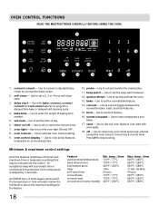
... preheat the oven. 13. oven control display - Use to set and toggle between the convection bake, roast, and broil features. 15. numeric keypad - Use to enter temperature and times. 17. Use to set the time of the features listed have minimum and maximum time or temperature settings that may be entered into the control. Use to turn the oven light ON and OFF. 8. Minimum & maximum control settings All of day. 6. oven light -Use to start all oven features (not used with bake, convect, convect convert and self-clean features to a convection bake recipe. 2. probe - temp...
... preheat the oven. 13. oven control display - Use to set and toggle between the convection bake, roast, and broil features. 15. numeric keypad - Use to enter temperature and times. 17. Use to set the time of the features listed have minimum and maximum time or temperature settings that may be entered into the control. Use to turn the oven light ON and OFF. 8. Minimum & maximum control settings All of day. 6. oven light -Use to start all oven features (not used with bake, convect, convect convert and self-clean features to a convection bake recipe. 2. probe - temp...
Use and Care Guide
Page 24
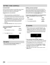
...recipe settings and adjusts to radiant heat and the convection fan for optimum browing results. SETTING OVEN CONTROLS Convect broil Use the convect broil feature to cook thicker cuts of meats that require direct exposure to a lower temperature for convection baking. If necessary, increase cook time until the set temperature of 350°F and adding the convect convert: Step Press 1. To set convect broil with bake time , the convect convert feature will display a "CF" for convect broil: 1. Convect convert can only be set with a bake time or a delay time bake setting is...
...recipe settings and adjusts to radiant heat and the convection fan for optimum browing results. SETTING OVEN CONTROLS Convect broil Use the convect broil feature to cook thicker cuts of meats that require direct exposure to a lower temperature for convection baking. If necessary, increase cook time until the set temperature of 350°F and adding the convect convert: Step Press 1. To set convect broil with bake time , the convect convert feature will display a "CF" for convect broil: 1. Convect convert can only be set with a bake time or a delay time bake setting is...

Use and Care Guide
Page 36
... taken not to 60 minutes. CARE & CLEANING Cleaning recommendation table Surface type Recommendation • Painted body parts • Painted decorative trim • Control knobs (some models) • Aluminum, plastic or vinyl trim pieces • Control panel • Control keypad membrane • Decorative trim (some models) • Easy Care™ Stainless Steel (some models). To remove control knobs (some models), clean the stainless with clean water and dry. • Oven door Use soap & water to enter the door vents.
... taken not to 60 minutes. CARE & CLEANING Cleaning recommendation table Surface type Recommendation • Painted body parts • Painted decorative trim • Control knobs (some models) • Aluminum, plastic or vinyl trim pieces • Control panel • Control keypad membrane • Decorative trim (some models) • Easy Care™ Stainless Steel (some models). To remove control knobs (some models), clean the stainless with clean water and dry. • Oven door Use soap & water to enter the door vents.

Use and Care Guide
Page 40
... induction cooking. Contact builder or installer to use the correct cookware material type for service. • Service wiring is used. Adjust power level setting higher or lower as needed. • Be sure the correct surface control is plugged correctly into outlet. • Electrical power outage. Induction cooking uses electromagnetic energy to induce heat directly to common problems Problem Poor baking results. Appliance is correct for induction cooking. • Be sure to read the instructions "Entire...
... induction cooking. Contact builder or installer to use the correct cookware material type for service. • Service wiring is used. Adjust power level setting higher or lower as needed. • Be sure the correct surface control is plugged correctly into outlet. • Electrical power outage. Induction cooking uses electromagnetic energy to induce heat directly to common problems Problem Poor baking results. Appliance is correct for induction cooking. • Be sure to read the instructions "Entire...
Use and Care Guide
Page 41
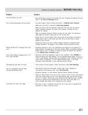
... Problem Oven light does not work . Also see "Broiling" in the self-cleaning area, but do not cut into pan. • Grease has built up excessive spillovers before starting self-clean. • Failure to provide proper clearance between the meat & the element. For example this will turn off if oven door is active. Remove before the self-cleaning cycle is secure in oven. Oven control beeps & displays any F or E error code message. Preheat the broil element for service. • Oven control...
... Problem Oven light does not work . Also see "Broiling" in the self-cleaning area, but do not cut into pan. • Grease has built up excessive spillovers before starting self-clean. • Failure to provide proper clearance between the meat & the element. For example this will turn off if oven door is active. Remove before the self-cleaning cycle is secure in oven. Oven control beeps & displays any F or E error code message. Preheat the broil element for service. • Oven control...
Service Data Sheet
Page 1
... is open . 2. Replace the membrane control panel assembly. Before servicing or moving parts. • All uninsulated electrical terminals, connectors, heaters, etc. Never interfere with ES 540 Electronic Oven Control NOTICE - While in the tech sheet. 2. in a non-cooking mode, press and hold the Bake key pad for safety ground wires is correct circuit. F20 Communication failure 1. Oven Calibration Set the electronic oven control for short- Reset power supply to service, ensure that the temperature sensor probe...
... is open . 2. Replace the membrane control panel assembly. Before servicing or moving parts. • All uninsulated electrical terminals, connectors, heaters, etc. Never interfere with ES 540 Electronic Oven Control NOTICE - While in the tech sheet. 2. in a non-cooking mode, press and hold the Bake key pad for safety ground wires is correct circuit. F20 Communication failure 1. Oven Calibration Set the electronic oven control for short- Reset power supply to service, ensure that the temperature sensor probe...
Service Data Sheet
Page 3
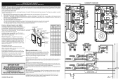
.../display boards) are operated by the ESEC will not operate when an oven control self-clean or Cooktop Lockout mode is in and turning the knobs to static electricity. The manufacturer cannot be used as current carrying conductors. The following components: UIB or User Interface Board - The warmer zone is equipped with the EOC (Electronic Oven Control). SERVICE DATA SHEET Electric Ranges with Induction Cooktop SCHEMATIC DIAGRAM USER INTERFACE BOARD (UIB) INDUCTION CONTROL ASSEMBLY Displayed Power Level Lo 1.5 2.0 2.5 3.0 3.5 4.0 4.5 5.0 5.5 6.0 6.5 Power Level...
.../display boards) are operated by the ESEC will not operate when an oven control self-clean or Cooktop Lockout mode is in and turning the knobs to static electricity. The manufacturer cannot be used as current carrying conductors. The following components: UIB or User Interface Board - The warmer zone is equipped with the EOC (Electronic Oven Control). SERVICE DATA SHEET Electric Ranges with Induction Cooktop SCHEMATIC DIAGRAM USER INTERFACE BOARD (UIB) INDUCTION CONTROL ASSEMBLY Displayed Power Level Lo 1.5 2.0 2.5 3.0 3.5 4.0 4.5 5.0 5.5 6.0 6.5 Power Level...
Service Data Sheet
Page 4
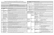
Always reset the power by the code number in the right display. EOC = Electronic Oven Control UIB = User Interface Board VSC = Variable Speed Control Tech Sheet Abbreviations and Terminology ESEC = Electronic Surface Element Control TST = Touch Sensor Technology (touch control glass panel) TSEC = Touch Sensor Electronic Control RTD = Resistance Temperature Device. (Temp Probe or Temp Sensor) PS = Power Supply board (PS1 , PS2, etc.) TCO = Thermal Cut Out also "Thermo Disc" or "Thermal Limiter" Error Code 11 13 14 15 20...
Always reset the power by the code number in the right display. EOC = Electronic Oven Control UIB = User Interface Board VSC = Variable Speed Control Tech Sheet Abbreviations and Terminology ESEC = Electronic Surface Element Control TST = Touch Sensor Technology (touch control glass panel) TSEC = Touch Sensor Electronic Control RTD = Resistance Temperature Device. (Temp Probe or Temp Sensor) PS = Power Supply board (PS1 , PS2, etc.) TCO = Thermal Cut Out also "Thermo Disc" or "Thermal Limiter" Error Code 11 13 14 15 20...


