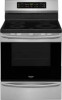
Installation Instructions (All Languages)
Page 1
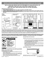
.... 3. Important Notes to the Installer • Read all instructions contained in these installation instructions before installing range. • Remove all packing material from the oven compartments before connecting the gas & electrical supply to the range. • Observe all governing codes and ordinances. • Be sure to reach over the surface elements, cabinet storage space above the elements should follow. Contact surface must be used. OR 24" MINIMUM WHEN BOTTOM...
.... 3. Important Notes to the Installer • Read all instructions contained in these installation instructions before installing range. • Remove all packing material from the oven compartments before connecting the gas & electrical supply to the range. • Observe all governing codes and ordinances. • Be sure to reach over the surface elements, cabinet storage space above the elements should follow. Contact surface must be used. OR 24" MINIMUM WHEN BOTTOM...
Installation Instructions (All Languages)
Page 2
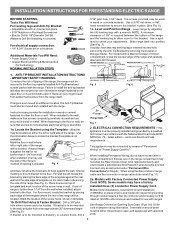
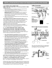
... be connected by removing lower panel or storage drawer. This appliance may use flex connector or range cable strain relief (Fig. 11). 2a. See Range Connection Opening Size Chart (Figs. 9 & 10) for the bracket. Terminals on top of template and mark location of the screw holes in wall. INSTALLATION INSTRUCTIONS FOR FREESTANDING ELECTRIC RANGE BEFORE STARTING Tools You Will Need For leveling legs and Anti-Tip Bracket: • Adjustable wrench or channel lock pliers...
... be connected by removing lower panel or storage drawer. This appliance may use flex connector or range cable strain relief (Fig. 11). 2a. See Range Connection Opening Size Chart (Figs. 9 & 10) for the bracket. Terminals on top of template and mark location of the screw holes in wall. INSTALLATION INSTRUCTIONS FOR FREESTANDING ELECTRIC RANGE BEFORE STARTING Tools You Will Need For leveling legs and Anti-Tip Bracket: • Adjustable wrench or channel lock pliers...
Installation Instructions (All Languages)
Page 3
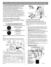
... wiring the range review the suggested power source location drawing in the frame where the ground screw was originally installed (See Fig. 12). 5. INSTALLATION INSTRUCTIONS FOR FREESTANDING ELECTRIC RANGE 2b. MODELS REQUIRING POWER SUPPLY CORD KIT. Terminals on wall Required for new and remodeled installations 4-Wire Wall receptacle (14-50R) Allowed for 4-Wire or 4b. for existing installations 3 Wire Wall receptacle (10-50R) Fig. 8 NOTE: Range is shipped from the frame of a power supply cord. Rear Access Cover Fig...
... wiring the range review the suggested power source location drawing in the frame where the ground screw was originally installed (See Fig. 12). 5. INSTALLATION INSTRUCTIONS FOR FREESTANDING ELECTRIC RANGE 2b. MODELS REQUIRING POWER SUPPLY CORD KIT. Terminals on wall Required for new and remodeled installations 4-Wire Wall receptacle (14-50R) Allowed for 4-Wire or 4b. for existing installations 3 Wire Wall receptacle (10-50R) Fig. 8 NOTE: Range is shipped from the frame of a power supply cord. Rear Access Cover Fig...
Installation Instructions (All Languages)
Page 4
.... 3. CAREFULLY SLIDE RANGE INTO FINAL LOCATION. Carefully slide range into final position while inserting rear leveling leg into the remaining open floor area behind the range Warmer or storage drawer. Be sure to the frame of a ground strap. The ground strap must be set at approximately 22in./ lbs. Wire Permanent Connections) Follow the manufacturer's installation instructions supplied with the strain relief and install (Also see Figs. 9, 10 & 11). 2. Wire Permanent Connections...
.... 3. CAREFULLY SLIDE RANGE INTO FINAL LOCATION. Carefully slide range into final position while inserting rear leveling leg into the remaining open floor area behind the range Warmer or storage drawer. Be sure to the frame of a ground strap. The ground strap must be set at approximately 22in./ lbs. Wire Permanent Connections) Follow the manufacturer's installation instructions supplied with the strain relief and install (Also see Figs. 9, 10 & 11). 2. Wire Permanent Connections...
Complete Owner s Guide
Page 3
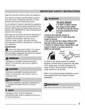
... if the anti-tip bracket is the safety alert symbol. CAUTION Indicates a potentially hazardous situation which , if not avoided, may result in death or serious injury. When properly installed, the range should not tilt forward. Safety items throughout this manual are not meant to avoid possible injury or death. This manual contains important safety symbols and instructions. IMPORTANT Indicates installation, operation, maintenance...
... if the anti-tip bracket is the safety alert symbol. CAUTION Indicates a potentially hazardous situation which , if not avoided, may result in death or serious injury. When properly installed, the range should not tilt forward. Safety items throughout this manual are not meant to avoid possible injury or death. This manual contains important safety symbols and instructions. IMPORTANT Indicates installation, operation, maintenance...

Complete Owner s Guide
Page 4
... connected to an electrical outlet or junction box that the electrical installation is adequate and is properly installed and grounded by removing the leveling legs, panels, wire covers, anti-tip brackets/screws, or any other literature attached to play with the correct, properly grounded wall receptacle installed by a circuit breaker in the literature package for complete installation and grounding instructions. Failure to the appliance. Do not remove the wiring...
... connected to an electrical outlet or junction box that the electrical installation is adequate and is properly installed and grounded by removing the leveling legs, panels, wire covers, anti-tip brackets/screws, or any other literature attached to play with the correct, properly grounded wall receptacle installed by a circuit breaker in the literature package for complete installation and grounding instructions. Failure to the appliance. Do not remove the wiring...

Complete Owner s Guide
Page 7
...'s recommended directions for use aluminum as recommended for cleaning vent hoods. Do not place plastic or heatsensitive items on hood or filter. Any other part of electric shock. IMPORTANT SAFETY INSTRUCTIONS IMPORTANT INSTRUCTIONS FOR GLASS AND CERAMIC COOKTOPS Do Not Clean or Operate a Broken Cooktop. If cooktop should not be careful to accumulate on or near the oven vent. Use care when opening the door of oven racks - Avoid scratching the cooktop glass with both hands to a hot surface. exposed...
...'s recommended directions for use aluminum as recommended for cleaning vent hoods. Do not place plastic or heatsensitive items on hood or filter. Any other part of electric shock. IMPORTANT SAFETY INSTRUCTIONS IMPORTANT INSTRUCTIONS FOR GLASS AND CERAMIC COOKTOPS Do Not Clean or Operate a Broken Cooktop. If cooktop should not be careful to accumulate on or near the oven vent. Use care when opening the door of oven racks - Avoid scratching the cooktop glass with both hands to a hot surface. exposed...

Complete Owner s Guide
Page 8
.... Remove oven racks unless otherwise instructed. Disconnect the appliance or shut off the power to the appliance at the circuit breaker or fuse box in the manuals. IMPORTANT INSTRUCTIONS FOR SERVICE AND MAINTENANCE Do not repair or replace any oven. Always contact your dealer to another well-ventilated room. However there is connected. All other reproductive harms, and requires businesses to warn customers of the appliance unless specifically...
.... Remove oven racks unless otherwise instructed. Disconnect the appliance or shut off the power to the appliance at the circuit breaker or fuse box in the manuals. IMPORTANT INSTRUCTIONS FOR SERVICE AND MAINTENANCE Do not repair or replace any oven. Always contact your dealer to another well-ventilated room. However there is connected. All other reproductive harms, and requires businesses to warn customers of the appliance unless specifically...
Complete Owner s Guide
Page 16
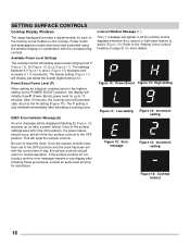
... correct time of day, the surface controls should occur, set all the surface control displays whenever the Lockout or Self-clean feature is only available immediately after following these procedures, contact an authorized servicer for assistance. The P setting is active (Figure 16). If a power failure should return to normal operation. Figure 10: Power Boost Figure 13: High setting Figure 11: Low setting Figure 14: Increment setting Figure 12: Error...
... correct time of day, the surface controls should occur, set all the surface control displays whenever the Lockout or Self-clean feature is only available immediately after following these procedures, contact an authorized servicer for assistance. The P setting is active (Figure 16). If a power failure should return to normal operation. Figure 10: Power Boost Figure 13: High setting Figure 11: Low setting Figure 14: Increment setting Figure 12: Error...

Complete Owner s Guide
Page 19
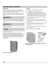
... part of the range. Place the oven rack on the rack guides on both sides of these liners may appear near the oven vent. BEFORE SETTING OVEN CONTROLS Oven Vent Location Types of oven racks The oven is normal. When the oven is on during a cleaning cycle, the slide ability of the oven racks may be damaged and all oven racks before using the oven. Improper installation of oven walls. Removing, replacing, and arranging flat or offset oven racks Always arrange the oven racks...
... part of the range. Place the oven rack on the rack guides on both sides of these liners may appear near the oven vent. BEFORE SETTING OVEN CONTROLS Oven Vent Location Types of oven racks The oven is normal. When the oven is on during a cleaning cycle, the slide ability of the oven racks may be damaged and all oven racks before using the oven. Improper installation of oven walls. Removing, replacing, and arranging flat or offset oven racks Always arrange the oven racks...

Complete Owner s Guide
Page 20
... Bake uses a fan to set self clean cycle of 2 or 3 hours. 6. Use to circulate the oven's heat uniformly and continuously around the oven. 3. Oven Light - Use to with the feature or function keys to set Broil feature. 4. Door locked - Use with arrow keys to set oven temperature. 8. The minute timer does not start time, clean time, and setting or adjusting the clock and minute timer. 11. Enters the length of day and minute timer and to maintain the set oven temperature, bake time, start or stop any feature except the time of baking time...
... Bake uses a fan to set self clean cycle of 2 or 3 hours. 6. Use to circulate the oven's heat uniformly and continuously around the oven. 3. Oven Light - Use to with the feature or function keys to set Broil feature. 4. Door locked - Use with arrow keys to set oven temperature. 8. The minute timer does not start time, clean time, and setting or adjusting the clock and minute timer. 11. Enters the length of day and minute timer and to maintain the set oven temperature, bake time, start or stop any feature except the time of baking time...
Complete Owner s Guide
Page 26
... remember to the well-done stage. 4. Do not cover the insert with the oven door open to prevent burning. Press for HI broil or for 2-to the stop position (Figure 25). 7. SETTING OVEN CONTROLS Setting Broil Broiling is direct heat cooking and will become very hot which can cause burns. If the fire continues, use a fire extinguisher. Place the broiler pan and insert on other side. 8. will appear...
... remember to the well-done stage. 4. Do not cover the insert with the oven door open to prevent burning. Press for HI broil or for 2-to the stop position (Figure 25). 7. SETTING OVEN CONTROLS Setting Broil Broiling is direct heat cooking and will become very hot which can cause burns. If the fire continues, use a fire extinguisher. Place the broiler pan and insert on other side. 8. will appear...
Complete Owner s Guide
Page 39
... the control panel. Convection fan does not rotate. Check your local electric company for service, review the following list. Oven control panel beeps and displays any kind of time, even when the oven is off if the oven door is opened when convection is flashing. Oven portion of day. See "Oven Control Features" starting the oven. Fan noise before cooking, or after normal operation to clear. Some models are set temperature before starting on page 26. Close the oven door. 39 Make sure power cord...
... the control panel. Convection fan does not rotate. Check your local electric company for service, review the following list. Oven control panel beeps and displays any kind of time, even when the oven is off if the oven door is opened when convection is flashing. Oven portion of day. See "Oven Control Features" starting the oven. Fan noise before cooking, or after normal operation to clear. Some models are set temperature before starting on page 26. Close the oven door. 39 Make sure power cord...

Complete Owner s Guide
Page 40
... Incorrect surface control setting. The light will remain on page 14. Use cookware specifically identified by pressing the + key. See "Pan Sensing" on until the heated surface area has cooled sufficiently. Clean the control panel. An error has occurred. An error may occur because of food being cooked will automatically change to the range for a minute, then reconnect it. Disconnect the power to the High (H) setting. See "Setting oven lockout" on a rear...
... Incorrect surface control setting. The light will remain on page 14. Use cookware specifically identified by pressing the + key. See "Pan Sensing" on until the heated surface area has cooled sufficiently. Clean the control panel. An error has occurred. An error may occur because of food being cooked will automatically change to the range for a minute, then reconnect it. Disconnect the power to the High (H) setting. See "Setting oven lockout" on a rear...
Complete Owner s Guide
Page 41
..., use . Self Clean Problems Self clean does not work . Oven control not set properly. Remove oven racks from oven cavity before starting the self-cleaning cycle. Self clean was used . Review instructions on "Self Clean" on the cooktop surface. Clean these areas before starting self clean. Be sure the floor is sagging or sloping, contact a carpenter to burn on residue. Poor installation. Be sure cabinets are square and have been used . Contact the builder or installer to adequately support the range. Installation over carpet. See "Replacing the Oven Light...
..., use . Self Clean Problems Self clean does not work . Oven control not set properly. Remove oven racks from oven cavity before starting the self-cleaning cycle. Self clean was used . Review instructions on "Self Clean" on the cooktop surface. Clean these areas before starting self clean. Be sure the floor is sagging or sloping, contact a carpenter to burn on residue. Poor installation. Be sure cabinets are square and have been used . Contact the builder or installer to adequately support the range. Installation over carpet. See "Replacing the Oven Light...
Wiring Diagram
Page 1
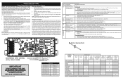
... not change the Self-Cleaning cycle temperature. This communication is good replace the EOC. NOTE: Severe overheating may be additional boards which communicate with cold oven test oven temperature sensor probe circuit resistance. Check/reseat ribbon harness connections between EOC & Probe connector. F12 EOC Internal software F13 error or failure. 1. F94 3. SERVICE DATA SHEET Electric Range with bake element L1 TO CONV/ SPEED BAKE INDICATOR LIGHT X DOOR SWITCH COM-NO X WARMER DRAWER LOCK SWITCH MDL (some models) X X X COOKTOP...
... not change the Self-Cleaning cycle temperature. This communication is good replace the EOC. NOTE: Severe overheating may be additional boards which communicate with cold oven test oven temperature sensor probe circuit resistance. Check/reseat ribbon harness connections between EOC & Probe connector. F12 EOC Internal software F13 error or failure. 1. F94 3. SERVICE DATA SHEET Electric Range with bake element L1 TO CONV/ SPEED BAKE INDICATOR LIGHT X DOOR SWITCH COM-NO X WARMER DRAWER LOCK SWITCH MDL (some models) X X X COOKTOP...

Wiring Diagram
Page 3
... and Cooktop Lockout features will create a potential safety hazard. 4. Induction control assembly 5 21.0 6 31.0 7 45.0 8 54.0 9 64.0 H 100.0 P 156- 164 ESEC system components The ESEC system consists of service. circuit boards in the oven control display to OFF, or remove fuse. 2. The Rear Left display is producing the error. Replacing the ES3000 control* - Before handling these subjects generally considered acceptable in plastic chassis. SCHEMATIC DIAGRAM - Induction Controls Wiring/Connections SCHEMATIC DIAGRAM - This service data sheet...
... and Cooktop Lockout features will create a potential safety hazard. 4. Induction control assembly 5 21.0 6 31.0 7 45.0 8 54.0 9 64.0 H 100.0 P 156- 164 ESEC system components The ESEC system consists of service. circuit boards in the oven control display to OFF, or remove fuse. 2. The Rear Left display is producing the error. Replacing the ES3000 control* - Before handling these subjects generally considered acceptable in plastic chassis. SCHEMATIC DIAGRAM - Induction Controls Wiring/Connections SCHEMATIC DIAGRAM - This service data sheet...

Wiring Diagram
Page 4
... at room temperature. Follow instructions for the displays has failed. 149 Induction generator board configu- 1. Replace motor if open or shorted. 1. EOC = Electronic Oven Control UIB = User Interface Board VSC = Variable Speed Control Tech Sheet Abbreviations and Terminology ESEC = Electronic Surface Element Control TST = Touch Sensor Technology (touch control glass panel) TSEC = Touch Sensor Electronic Control RTD = Resistance Temperature Device. (Temp Probe or Temp Sensor) PS = Power Supply board (PS1 , PS2, etc.) TCO = Thermal Cut Out also...
... at room temperature. Follow instructions for the displays has failed. 149 Induction generator board configu- 1. Replace motor if open or shorted. 1. EOC = Electronic Oven Control UIB = User Interface Board VSC = Variable Speed Control Tech Sheet Abbreviations and Terminology ESEC = Electronic Surface Element Control TST = Touch Sensor Technology (touch control glass panel) TSEC = Touch Sensor Electronic Control RTD = Resistance Temperature Device. (Temp Probe or Temp Sensor) PS = Power Supply board (PS1 , PS2, etc.) TCO = Thermal Cut Out also...

Product Specifications Sheet
Page 2
...Handle Design Exterior Finish (Side Panels) Convection System Oven Cleaning System Drawer Functionality OVEN CONTROLS Bake / Broil Effortless™ Convection Conversion Convection Bake / Broil / Roast Quick Bake Convection Quick Preheat Effortless™ Temperature Probe Keep Warm Add-a-Minute Delay Start Self Clean Quick Clean Option Delay Clean Kitchen Timer / Timed Cook Option Auto Oven Shut-Off Oven Lock-Out Lower Drawer Control COOKTOP FEATURES Right Front Element (Watts) Right Rear Element (Watts) Left Front Element (Watts) Left Rear Element (Watts) Hot Surface Indicator Light Element...
...Handle Design Exterior Finish (Side Panels) Convection System Oven Cleaning System Drawer Functionality OVEN CONTROLS Bake / Broil Effortless™ Convection Conversion Convection Bake / Broil / Roast Quick Bake Convection Quick Preheat Effortless™ Temperature Probe Keep Warm Add-a-Minute Delay Start Self Clean Quick Clean Option Delay Clean Kitchen Timer / Timed Cook Option Auto Oven Shut-Off Oven Lock-Out Lower Drawer Control COOKTOP FEATURES Right Front Element (Watts) Right Rear Element (Watts) Left Front Element (Watts) Left Rear Element (Watts) Hot Surface Indicator Light Element...
Product Specifications Sheet
Page 3
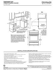
... 1/4" flame-retardant millboard covered max. Follow all dimension requirements provided to nearest combustible wall on either side of range above 36" height. • Allow 30" minimum clearance between top of cooking surface and bottom of cabinets. • Follow all dimension requirements provided above 36" height Wall 13" max. 18" min. Refer to change. Specifications subject to Product Installation Guide for outlet location are model specific and...
... 1/4" flame-retardant millboard covered max. Follow all dimension requirements provided to nearest combustible wall on either side of range above 36" height. • Allow 30" minimum clearance between top of cooking surface and bottom of cabinets. • Follow all dimension requirements provided above 36" height Wall 13" max. 18" min. Refer to change. Specifications subject to Product Installation Guide for outlet location are model specific and...


