
Complete Owner's Guide (English)
Page 3
... or foam-type extinguisher. • When heating fat or grease, watch it closely. Loose-fitting or hanging garments should not be worn while using the appliance. Do not use a towel or other permanent part of interest to the appliance at the circuit breaker or fuse box in the cabinets above the appliance. Important Safety Instructions Read all instructions before using the appliance. Areas near surface...
... or foam-type extinguisher. • When heating fat or grease, watch it closely. Loose-fitting or hanging garments should not be worn while using the appliance. Do not use a towel or other permanent part of interest to the appliance at the circuit breaker or fuse box in the cabinets above the appliance. Important Safety Instructions Read all instructions before using the appliance. Areas near surface...
Complete Owner's Guide (English)
Page 4
... for cleaning. • Use Proper Pan Size. Important Safety Instructions IMPORTANT SAFETY INSTRUCTIONS FOR USING YOUR COOKTOP • Know which knob controls each surface unit. • Clean the appliance regularly to keep all parts free of grease that could cause glass to break. • Do not slide pan across the cooktop surface. Any other reproductive harm, and requires businesses to warn customers of utensil to element will occur if the hot covers are suitable...
... for cleaning. • Use Proper Pan Size. Important Safety Instructions IMPORTANT SAFETY INSTRUCTIONS FOR USING YOUR COOKTOP • Know which knob controls each surface unit. • Clean the appliance regularly to keep all parts free of grease that could cause glass to break. • Do not slide pan across the cooktop surface. Any other reproductive harm, and requires businesses to warn customers of utensil to element will occur if the hot covers are suitable...

Complete Owner's Guide (English)
Page 5
... heat to complete the cooking process. Model B 5 The type and size of cookware, the number of surface elements in the General Care & Cleaning section and Before You Call checklist section of the element outline on the 30" cooktop as the element wattage increases. This will glow red. Before SETTING SURFACE CONTROLS About the Ceramic Glass Cooktop The ceramic cooktop has radiant surface elements located below the surface of the surface radiant elements Your cooktop is equipped with radiant surface radiant elements with different wattage ratings. Fig. 1 - 30" Model Cooktop...
... heat to complete the cooking process. Model B 5 The type and size of cookware, the number of surface elements in the General Care & Cleaning section and Before You Call checklist section of the element outline on the 30" cooktop as the element wattage increases. This will glow red. Before SETTING SURFACE CONTROLS About the Ceramic Glass Cooktop The ceramic cooktop has radiant surface elements located below the surface of the surface radiant elements Your cooktop is equipped with radiant surface radiant elements with different wattage ratings. Fig. 1 - 30" Model Cooktop...

Complete Owner's Guide (English)
Page 6
... 12 inch radiant element located at the left front position. • One 7 inch radiant element located at center rear position. NOTE Due to its original white color after it is in use. Note: The size and type of Cooking HIGH (HI) Start most foods; MEDIUM (6) Maintain a slow boil; This helps to prevent damage to a boil and pan broiling. frying, deep fat (8-10) frying. Model D 6 CAUTION...
... 12 inch radiant element located at the left front position. • One 7 inch radiant element located at center rear position. NOTE Due to its original white color after it is in use. Note: The size and type of Cooking HIGH (HI) Start most foods; MEDIUM (6) Maintain a slow boil; This helps to prevent damage to a boil and pan broiling. frying, deep fat (8-10) frying. Model D 6 CAUTION...
Complete Owner's Guide (English)
Page 7
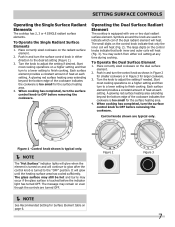
... control knobs indicate that only the inner coil will glow until the heating surface area has cooled sufficiently. The message may switch from either direction to finish cooking. To Operate the Single Radiant Surface Elements 1. Push in either coil setting at each setting. Push in Figure 3 for the surface heating area. 4. When cooking has completed, turn to a lower setting to OFF before removing the cookware. When cooking has completed, turn the control knob...
... control knobs indicate that only the inner coil will glow until the heating surface area has cooled sufficiently. The message may switch from either direction to finish cooking. To Operate the Single Radiant Surface Elements 1. Push in either coil setting at each setting. Push in Figure 3 for the surface heating area. 4. When cooking has completed, turn to a lower setting to OFF before removing the cookware. When cooking has completed, turn the control knob...
Complete Owner's Guide (English)
Page 8
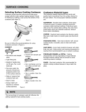
... on ceramic cooktops. A poor heat conductor however will resemble scratches. Porcelain-enamel coating must be prepared and the size of the surface element. • Made of cookware used will vary depending on METAL - Some types of handle does not tilt pan. COPPER - STAINLESS STEEL - Not recommended for best cooking results. 8 Heating characteristics will influence the setting needed for use on ceramic glass (see Aluminum above). Slow heat conductor. SURFACE COOKING Selecting Surface Cooking Cookware...
... on ceramic cooktops. A poor heat conductor however will resemble scratches. Porcelain-enamel coating must be prepared and the size of the surface element. • Made of cookware used will vary depending on METAL - Some types of handle does not tilt pan. COPPER - STAINLESS STEEL - Not recommended for best cooking results. 8 Heating characteristics will influence the setting needed for use on ceramic glass (see Aluminum above). Slow heat conductor. SURFACE COOKING Selecting Surface Cooking Cookware...

Complete Owner's Guide (English)
Page 9
... the controls. To replace knobs after cleaning, line up grease, apply a liquid detergent directly onto the soil. then push the knob into place. Prior to using hot, soapy water and a cloth. The special cooktop cleaning cream leaves a protective finish on the cooktop surface without a pan. These marks should be removed. Surfaces Painted and Plastic Body Parts Stainless Steel Decorative Trim Cooktop, Control Knobs, Control Panel Ceramic Glass Cooktop How to Clean For general cleaning, use harsh scrubbing cleaners. Leave on soil for cleaning stainless steel...
... the controls. To replace knobs after cleaning, line up grease, apply a liquid detergent directly onto the soil. then push the knob into place. Prior to using hot, soapy water and a cloth. The special cooktop cleaning cream leaves a protective finish on the cooktop surface without a pan. These marks should be removed. Surfaces Painted and Plastic Body Parts Stainless Steel Decorative Trim Cooktop, Control Knobs, Control Panel Ceramic Glass Cooktop How to Clean For general cleaning, use harsh scrubbing cleaners. Leave on soil for cleaning stainless steel...

Complete Owner's Guide (English)
Page 10
... type scratch pad. After turning the surface elements OFF, use under any other metals, care must be taken when aluminum pots or pans are used. Do not use a razor blade scraper or a metal spatula with a metal razor blade scraper, holding scraper at a 30 degree angle to the General Care & Cleaning table for detailed cleaning instructions. Remove loosened soils, then apply a few drops of CookTop® Cleaning Creme directly to cool, and use to clean...
... type scratch pad. After turning the surface elements OFF, use under any other metals, care must be taken when aluminum pots or pans are used. Do not use a razor blade scraper or a metal spatula with a metal razor blade scraper, holding scraper at a 30 degree angle to the General Care & Cleaning table for detailed cleaning instructions. Remove loosened soils, then apply a few drops of CookTop® Cleaning Creme directly to cool, and use to clean...

Complete Owner's Guide (English)
Page 11
.../reset breaker or replace fuse. Surface element too hot or not hot enough. Dial markings are not the result of heat is incorrect. Food not heating evenly. Raise or lower setting until element comes on. Use flat-bottomed, smooth utensils. Metal marks on ceramic glass cooktop surface. See CeramicGlass Cooktop section in this Owner's Guide. 11 No power to a slightly higher setting until proper amount of defective workmanship or materials in this Owner's Guide. Incorrect control setting...
.../reset breaker or replace fuse. Surface element too hot or not hot enough. Dial markings are not the result of heat is incorrect. Food not heating evenly. Raise or lower setting until element comes on. Use flat-bottomed, smooth utensils. Metal marks on ceramic glass cooktop surface. See CeramicGlass Cooktop section in this Owner's Guide. 11 No power to a slightly higher setting until proper amount of defective workmanship or materials in this Owner's Guide. Incorrect control setting...
Complete Owner's Guide (English)
Page 12
... appliance is installed, used other appropriate payment record to any breach of this warranty. Exclusions This warranty does not cover the following: 1 Products with original serial numbers that have other rights that vary from the factory. 10 Service calls to repair or replace appliance light bulbs, air filters, water filters, other consumable, or knobs, handles, or other than in accordance with the provided instructions. 8 Service calls to...
... appliance is installed, used other appropriate payment record to any breach of this warranty. Exclusions This warranty does not cover the following: 1 Products with original serial numbers that have other rights that vary from the factory. 10 Service calls to repair or replace appliance light bulbs, air filters, water filters, other consumable, or knobs, handles, or other than in accordance with the provided instructions. 8 Service calls to...

Installation Instructions (All Languages)
Page 1
... use gasoline or other flammable vapors and liquids in Canada. * Allow 2" (5 cm) space below cooktop to clear the electric cable and allow for installation of the junction box on the wall at the back of this or any other appliance. for protected surface Figure 1 MODEL A. WIDTH 26" Coil Elements 30" Ceramic Glass 30" Coil Elements 32" Ceramic Glass 32" Coil Elements 36" Ceramic Glass 36" Coil Elements (36" X 18") 36" Coil Elements...
... use gasoline or other flammable vapors and liquids in Canada. * Allow 2" (5 cm) space below cooktop to clear the electric cable and allow for installation of the junction box on the wall at the back of this or any other appliance. for protected surface Figure 1 MODEL A. WIDTH 26" Coil Elements 30" Ceramic Glass 30" Coil Elements 32" Ceramic Glass 32" Coil Elements 36" Ceramic Glass 36" Coil Elements (36" X 18") 36" Coil Elements...

Installation Instructions (All Languages)
Page 2
... instructions with the electrical installation of burns or fire by Not Less Than 1/8" Flame Retardant Millboard Covered With Not Less Than No. 28 MGS Sheet Steel, 0.015" (0.4 mm) Stainless Steel, 0.024" (0.6 mm) Aluminum or 0.020" (0.5 mm) Copper 2 1/2" (6.4 cm) Min. From Edge of Cutout to Front Edge of Junction Box * Letters on front page except for future reference. 2 Approximate Location of Countertop A Min. MODEL 26" Coil Elements 30" Ceramic-Glass 30...
... instructions with the electrical installation of burns or fire by Not Less Than 1/8" Flame Retardant Millboard Covered With Not Less Than No. 28 MGS Sheet Steel, 0.015" (0.4 mm) Stainless Steel, 0.024" (0.6 mm) Aluminum or 0.020" (0.5 mm) Copper 2 1/2" (6.4 cm) Min. From Edge of Cutout to Front Edge of Junction Box * Letters on front page except for future reference. 2 Approximate Location of Countertop A Min. MODEL 26" Coil Elements 30" Ceramic-Glass 30...

Installation Instructions (All Languages)
Page 3
... local code and ordinances. Such use . ELECTRIC COOKTOP INSTALLATION INSTRUCTIONS IMPORTANT SAFETY INSTRUCTIONS • Be sure your cooktop is installed and grounded properly by a qualified installer or service technician. • These cooktops must be supplied with the proper voltage and frequency, and connected to an individual, properly grounded branch circuit, protected by a circuit breaker or fuse. Electrical Requirements This appliance must be shut off while line connections are being made to aluminum house wiring, use...
... local code and ordinances. Such use . ELECTRIC COOKTOP INSTALLATION INSTRUCTIONS IMPORTANT SAFETY INSTRUCTIONS • Be sure your cooktop is installed and grounded properly by a qualified installer or service technician. • These cooktops must be supplied with the proper voltage and frequency, and connected to an individual, properly grounded branch circuit, protected by a circuit breaker or fuse. Electrical Requirements This appliance must be shut off while line connections are being made to aluminum house wiring, use...
Installation Instructions (All Languages)
Page 4
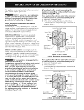
... in Canada, disconnect the white and green lead from each other and use ground lead to ground unit in accordance with a white neutral power supply and a frame connected copper wire. recreational vehicules; Where local codes permit connecting the appliance-grounding conductor to the neutral (white) wire (USA only): Your appliance has a 3-wire cable to be 150V to larger gauge household wiring. In the circuit breaker, fuse box...
... in Canada, disconnect the white and green lead from each other and use ground lead to ground unit in accordance with a white neutral power supply and a frame connected copper wire. recreational vehicules; Where local codes permit connecting the appliance-grounding conductor to the neutral (white) wire (USA only): Your appliance has a 3-wire cable to be 150V to larger gauge household wiring. In the circuit breaker, fuse box...
Installation Instructions (All Languages)
Page 5
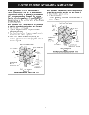
... circuit breaker, fuse box or junction box: Connect appliance and power supply cable wires as shown in figure 6. In the junction box: Connect appliance and power supply cable wires as shown in Figure 7. Cap the white wire from Power Supply Ground Wire Red Wires White Wire Black Wires Your appliance has a 4-wire cable to be connected to a 4-wire grounded junction box (see figure 6): 1. Cable from the power supply cable if a 3-wire appliance cable is used in a new branch circuit installation...
... circuit breaker, fuse box or junction box: Connect appliance and power supply cable wires as shown in figure 6. In the junction box: Connect appliance and power supply cable wires as shown in Figure 7. Cap the white wire from Power Supply Ground Wire Red Wires White Wire Black Wires Your appliance has a 4-wire cable to be connected to a 4-wire grounded junction box (see figure 6): 1. Cable from the power supply cable if a 3-wire appliance cable is used in a new branch circuit installation...

Installation Instructions (All Languages)
Page 6
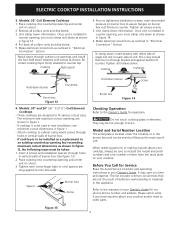
... cutout center line (CL) Cooktop Countertop Screw Burner box Figure 11 6 Lift the cooktop and fasten the ends of the cooktop. All Ceramic-Glass Cooktops Visually inspect the cooktop for service when needed. WARNING Do not remove the built in their absence, with the National Electrical Code ANSI/NFPA No. 70-latest edition, or with wood screws (figure 11). ELECTRIC COOKTOP INSTALLATION INSTRUCTIONS Cooktop Installation 1. Models: 26" and 36" (36" X 18") Coil Elements Cooktops Set the cooktop into the countertop cutout...
... cutout center line (CL) Cooktop Countertop Screw Burner box Figure 11 6 Lift the cooktop and fasten the ends of the cooktop. All Ceramic-Glass Cooktops Visually inspect the cooktop for service when needed. WARNING Do not remove the built in their absence, with the National Electrical Code ANSI/NFPA No. 70-latest edition, or with wood screws (figure 11). ELECTRIC COOKTOP INSTALLATION INSTRUCTIONS Cooktop Installation 1. Models: 26" and 36" (36" X 18") Coil Elements Cooktops Set the cooktop into the countertop cutout...
Installation Instructions (All Languages)
Page 7
... your cooktop. Model and Serial Number Location The serial plate is installed in counter opening (not exceeding maximum cutout dimensions as outlined in cutout. 3. When ordering parts for Service Read the Avoid Service Checklist and operating instructions in your Owner's Guide. Remove all surface units and drip bowls. 3. Unit clamp down information. Once unit is to burn. Make electrical connections as shown in the burner box and can be sure to fit various cutout sizes...
... your cooktop. Model and Serial Number Location The serial plate is installed in counter opening (not exceeding maximum cutout dimensions as outlined in cutout. 3. When ordering parts for Service Read the Avoid Service Checklist and operating instructions in your Owner's Guide. Remove all surface units and drip bowls. 3. Unit clamp down information. Once unit is to burn. Make electrical connections as shown in the burner box and can be sure to fit various cutout sizes...

Installation Instructions (All Languages)
Page 8
... to junction box. Cabinet side filler height should allow for 30" models. * If no cooktop is allowed above the floor. 27" (68.6cm) Wall Oven 30" (76.2cm) Wall Oven CUTOUT DIMENSIONS F. HEIGHT 27¼" (69.2cm) Min. 28¼" (71.8cm) Max. 27¼" (69.2cm) Min. 28¼" (71.8cm) Max. TYPICAL UNDER COUNTER INSTALLATION OF A SINGLE ELECTRIC BUILT-IN OVEN WITH AN ELECTRIC COOKTOP MOUNTED ABOVE 8 by...
... to junction box. Cabinet side filler height should allow for 30" models. * If no cooktop is allowed above the floor. 27" (68.6cm) Wall Oven 30" (76.2cm) Wall Oven CUTOUT DIMENSIONS F. HEIGHT 27¼" (69.2cm) Min. 28¼" (71.8cm) Max. 27¼" (69.2cm) Min. 28¼" (71.8cm) Max. TYPICAL UNDER COUNTER INSTALLATION OF A SINGLE ELECTRIC BUILT-IN OVEN WITH AN ELECTRIC COOKTOP MOUNTED ABOVE 8 by...
Product Specifications Sheet (English)
Page 2
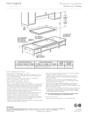
... instructions. Height Product Cutout Dimensions D - Width E - Printed in combination with ground required on separate circuit fused on both sides of line. • Connected Load (kW Rating) @ 240 / 208 Volts = 8.4 /6.3 kW • Amps @ 240 / 208 Volts = 35.0 / 30.0 Amps • Recommended Circuit Breaker - 40 Amps • Always consult local and national electric codes. • Allow 2" space beneath cooktop or optional platform to Product Installation Guide on wall at frigidaire.com for installation of cabinets. • Electric Drop...
... instructions. Height Product Cutout Dimensions D - Width E - Printed in combination with ground required on separate circuit fused on both sides of line. • Connected Load (kW Rating) @ 240 / 208 Volts = 8.4 /6.3 kW • Amps @ 240 / 208 Volts = 35.0 / 30.0 Amps • Recommended Circuit Breaker - 40 Amps • Always consult local and national electric codes. • Allow 2" space beneath cooktop or optional platform to Product Installation Guide on wall at frigidaire.com for installation of cabinets. • Electric Drop...
Product Specifications Sheet (English)
Page 3
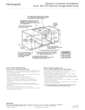
...; Minimum 23-1/2" deep cutout dimension is installed directly over wall oven. Electric Cooktop Installation Over 30"/ 27" Electric Single Wall Oven Specifications All Frigidaire® Electric Single Wall Ovens are approved to isolate oven from oven base to floor, if NO cooktop is installed directly over two runners and flush with ground required on separate circuit fused on the web at frigidaire.com for proper installation, to junction box, cut minimum 4" x 4" opening in the U.S.A. Specifications subject to Product Installation Guide on both sides of supporting 200...
...; Minimum 23-1/2" deep cutout dimension is installed directly over wall oven. Electric Cooktop Installation Over 30"/ 27" Electric Single Wall Oven Specifications All Frigidaire® Electric Single Wall Ovens are approved to isolate oven from oven base to floor, if NO cooktop is installed directly over two runners and flush with ground required on separate circuit fused on the web at frigidaire.com for proper installation, to junction box, cut minimum 4" x 4" opening in the U.S.A. Specifications subject to Product Installation Guide on both sides of supporting 200...


