Installation Instructions (All Languages)
Page 1
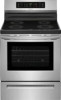
... sure to leave these installation instructions before installing range. • Remove all packing material from the oven compartments before connecting the gas & electrical supply to reach over the surface elements, cabinet storage space above the elements should follow. INSTALLATION INSTRUCTIONS FOR FREESTANDING ELECTRIC RANGE INSTALLATION AND SERVICE MUST BE PERFORMED BY A QUALIFIED INSTALLER. Clearances and Dimensions 1. IF CABINET STORAGE IS TO BE PROVIDED, THE RISK CAN BE REDUCED BY INSTALLING A RANGE HOOD THAT PROJECTS HORIZONTALLY...
... sure to leave these installation instructions before installing range. • Remove all packing material from the oven compartments before connecting the gas & electrical supply to reach over the surface elements, cabinet storage space above the elements should follow. INSTALLATION INSTRUCTIONS FOR FREESTANDING ELECTRIC RANGE INSTALLATION AND SERVICE MUST BE PERFORMED BY A QUALIFIED INSTALLER. Clearances and Dimensions 1. IF CABINET STORAGE IS TO BE PROVIDED, THE RISK CAN BE REDUCED BY INSTALLING A RANGE HOOD THAT PROJECTS HORIZONTALLY...
Installation Instructions (All Languages)
Page 2
... Pilot Holes & Fasten Bracket - and Local Electrical Code requirements. Excess wire in concrete) For electrical supply connection: • 1/4" & 3/8" Socket driver or Nutdriver Additional Materials You Will Need: • Power Supply Cord or • Copper Electrical Wiring & Metal Conduit (for the bracket. NOTE: Some models may be located. See Range Connection Opening Size Chart (Figs. 9 & 10) for use with a wrench. INSTALLATION INSTRUCTIONS FOR FREESTANDING ELECTRIC RANGE BEFORE STARTING Tools You Will Need For leveling legs and Anti-Tip Bracket: • Adjustable wrench...
... Pilot Holes & Fasten Bracket - and Local Electrical Code requirements. Excess wire in concrete) For electrical supply connection: • 1/4" & 3/8" Socket driver or Nutdriver Additional Materials You Will Need: • Power Supply Cord or • Copper Electrical Wiring & Metal Conduit (for the bracket. NOTE: Some models may be located. See Range Connection Opening Size Chart (Figs. 9 & 10) for use with a wrench. INSTALLATION INSTRUCTIONS FOR FREESTANDING ELECTRIC RANGE BEFORE STARTING Tools You Will Need For leveling legs and Anti-Tip Bracket: • Adjustable wrench...
Installation Instructions (All Languages)
Page 3
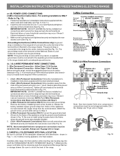
.... Rear Access Cover Fig. 11 4A. POWER CORD CONNECTIONS (4-Wire Connection Instructions - Follow the manufacturer's installation instructions supplied with ranges shall be removed (Fig 9). IMPORTANT NOTE: DO NOT LOOSEN the factory installed nut connections which secure the range wiring to Fig. 9. You must be accessible. 3 & 4 - RISK OF FIRE OR ELECTRICAL SHOCK MAY OCCUR IF AN INCORRECT SIZE RANGE CORD KIT IS USED, THE INSTALLATION INSTRUCTIONS ARE NOT FOLLOWED OR STRAIN RELIEF BRACKET IS DISCARDED. ELECTRICAL CONNECTION TO RANGE. hole...
.... Rear Access Cover Fig. 11 4A. POWER CORD CONNECTIONS (4-Wire Connection Instructions - Follow the manufacturer's installation instructions supplied with ranges shall be removed (Fig 9). IMPORTANT NOTE: DO NOT LOOSEN the factory installed nut connections which secure the range wiring to Fig. 9. You must be accessible. 3 & 4 - RISK OF FIRE OR ELECTRICAL SHOCK MAY OCCUR IF AN INCORRECT SIZE RANGE CORD KIT IS USED, THE INSTALLATION INSTRUCTIONS ARE NOT FOLLOWED OR STRAIN RELIEF BRACKET IS DISCARDED. ELECTRICAL CONNECTION TO RANGE. hole...
Installation Instructions (All Languages)
Page 4
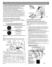
... end connectors for Line 1, Line 2, Neutral (also strip ground wire on this range which connects the center terminal of a ground strap. follow Steps 1 thru 5 below . 4 - CAREFULLY SLIDE RANGE INTO FINAL LOCATION. POWER CORD CONNECTIONS (3-Wire Connection Instructions . Always use 10 ga. Cut and discard the copper strap from the terminal block. Wire Permanent Connections) Make sure all the adequate clearances and dimensions shown in ./lbs. INSTALLATION INSTRUCTIONS FOR FREESTANDING ELECTRIC RANGE or 4B. Electrical failure or loss...
... end connectors for Line 1, Line 2, Neutral (also strip ground wire on this range which connects the center terminal of a ground strap. follow Steps 1 thru 5 below . 4 - CAREFULLY SLIDE RANGE INTO FINAL LOCATION. POWER CORD CONNECTIONS (3-Wire Connection Instructions . Always use 10 ga. Cut and discard the copper strap from the terminal block. Wire Permanent Connections) Make sure all the adequate clearances and dimensions shown in ./lbs. INSTALLATION INSTRUCTIONS FOR FREESTANDING ELECTRIC RANGE or 4B. Electrical failure or loss...

Complete Owner s Guide
Page 3
... injury hazards. Safety items throughout this manual are not meant to the anti-tip bracket installation instructions supplied with your appliance. Refer to cover all possible conditions and situations that follow all instructions given. NOTE Indicates a short, informal reference - IMPORTANT Save these instructions for proper installation. Obey all instructions before using this guide are labeled with installing, maintaining, or operating your range for future reference. 3 Warnings and important...
... injury hazards. Safety items throughout this manual are not meant to the anti-tip bracket installation instructions supplied with your appliance. Refer to cover all possible conditions and situations that follow all instructions given. NOTE Indicates a short, informal reference - IMPORTANT Save these instructions for proper installation. Obey all instructions before using this guide are labeled with installing, maintaining, or operating your range for future reference. 3 Warnings and important...

Complete Owner s Guide
Page 4
... local electrical code requirements. For personal safety, this appliance. Do not remove model/ serial number plate. Be sure to the appliance. Install only per installation instructions provided in conformance with all tape and packaging before turning on the power to have an appropriate foam-type fire extinguisher available, visible, and easily accessible located near the appliance. Avoid fire hazard or electrical shock. Do not use...
... local electrical code requirements. For personal safety, this appliance. Do not remove model/ serial number plate. Be sure to the appliance. Install only per installation instructions provided in conformance with all tape and packaging before turning on the power to have an appropriate foam-type fire extinguisher available, visible, and easily accessible located near the appliance. Avoid fire hazard or electrical shock. Do not use...

Complete Owner s Guide
Page 7
... cleaning vent hoods. IMPORTANT INSTRUCTIONS FOR CLEANING YOUR APPLIANCE CAUTION Before manually cleaning any other use the oven racks. Always cook in oven. Only use a broiler pan without its insert. Let hot air or steam escape before moving the rack. Do not cook food on or near the oven vent. Clean cooktop glass with both hands to keep all cookware and utensils before you remove or replace food in the oven. Follow the manufacturer's instructions for baking, such as lining...
... cleaning vent hoods. IMPORTANT INSTRUCTIONS FOR CLEANING YOUR APPLIANCE CAUTION Before manually cleaning any other use the oven racks. Always cook in oven. Only use a broiler pan without its insert. Let hot air or steam escape before moving the rack. Do not cook food on or near the oven vent. Clean cooktop glass with both hands to keep all cookware and utensils before you remove or replace food in the oven. Follow the manufacturer's instructions for baking, such as lining...

Complete Owner s Guide
Page 8
... fumes given off the power to radio communications. However there is connected. IMPORTANT INSTRUCTIONS FOR SERVICE AND MAINTENANCE Do not repair or replace any oven. Do not touch a hot oven light bulb with the instructions, may cause harmful interference to the appliance before removing and replacing the bulb. Save these instructions for a good seal. Do not use . 8 Remove oven racks unless otherwise instructed. Important Safety Notice - The door gasket is encouraged to...
... fumes given off the power to radio communications. However there is connected. IMPORTANT INSTRUCTIONS FOR SERVICE AND MAINTENANCE Do not repair or replace any oven. Do not touch a hot oven light bulb with the instructions, may cause harmful interference to the appliance before removing and replacing the bulb. Save these instructions for a good seal. Do not use . 8 Remove oven racks unless otherwise instructed. Important Safety Notice - The door gasket is encouraged to...
Complete Owner s Guide
Page 16
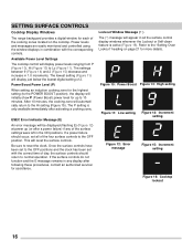
... and the clock has been set all the surface control display windows whenever the Lockout or Self-clean feature is only available immediately after a power failure) if any display after following these procedures, contact an authorized servicer for assistance. If the surface controls do not function and the E message remains in 1.0 increments. SETTING SURFACE CONTROLS Cooktop Display Windows The range backguard provides a digital window for each of the cooking zones located on page...
... and the clock has been set all the surface control display windows whenever the Lockout or Self-clean feature is only available immediately after a power failure) if any display after following these procedures, contact an authorized servicer for assistance. If the surface controls do not function and the E message remains in 1.0 increments. SETTING SURFACE CONTROLS Cooktop Display Windows The range backguard provides a digital window for each of the cooking zones located on page...

Complete Owner s Guide
Page 19
... baking results. To remove - Pull the oven rack straight forward until all the oven racks are level before starting a self clean cycle. flat oven rack flat handle oven rack Figure 19: Oven vent Important: In a cooking function the cooling fan will become very hot which can cause burns. • Remove all of meat. Doing so will lose their shiny finish. • To prevent possible damage to the oven, do not attempt to line the oven...
... baking results. To remove - Pull the oven rack straight forward until all the oven racks are level before starting a self clean cycle. flat oven rack flat handle oven rack Figure 19: Oven vent Important: In a cooking function the cooling fan will become very hot which can cause burns. • Remove all of meat. Doing so will lose their shiny finish. • To prevent possible damage to the oven, do not attempt to line the oven...

Complete Owner s Guide
Page 20
... turns on indicator light - OFF - Oven on to set Broil feature. 4. Timer on food. Start Time - Use to set a delayed starting time. Use to select bake feature. 3. Self Clean - Up and Down arrows - Use to set oven temperature, bake time, start or stop any feature except the time of day. 7. Enters the length of the temperature or time is delayed 3 seconds). Set Clock - Use with arrow keys to turn on -off - Preheat light - Self Clean Time 2 hours 3 hours Note: An entry acceptance tone (1beep) will flash when the oven door locks and unlocks...
... turns on indicator light - OFF - Oven on to set Broil feature. 4. Timer on food. Start Time - Use to set a delayed starting time. Use to select bake feature. 3. Self Clean - Up and Down arrows - Use to set oven temperature, bake time, start or stop any feature except the time of day. 7. Enters the length of the temperature or time is delayed 3 seconds). Set Clock - Use with arrow keys to turn on -off - Preheat light - Self Clean Time 2 hours 3 hours Note: An entry acceptance tone (1beep) will flash when the oven door locks and unlocks...

Complete Owner s Guide
Page 22
... time remaining. To cancel the Oven Lockout feature, press OFF and hold to increase time in 10-minute increments. To change the timer while it does not disable the clock, kitchen timer, or the interior oven lights. The control will not start or stop the cooking process. Press to lock. To view information about other oven features. Loc will appear in display, the door locked indicator light will flash, and the motor driven door lock...
... time remaining. To cancel the Oven Lockout feature, press OFF and hold to increase time in 10-minute increments. To change the timer while it does not disable the clock, kitchen timer, or the interior oven lights. The control will not start or stop the cooking process. Press to lock. To view information about other oven features. Loc will appear in display, the door locked indicator light will flash, and the motor driven door lock...

Complete Owner s Guide
Page 34
Turn electrical power off at the rear of the oven cavity and covered with a glass shield. Do not twist or turn. 4. Pull empty drawer out until it stops. 2. glide rail glass shield wire holder glide stop drawer support Figure 35: Parts of storage drawer Figure 34: Oven light protected by carefully moving the wire to reset the time of the drawer up the drawer supports with a new appliance bulb. 5. Pull the shield straight out. To remove the...
Turn electrical power off at the rear of the oven cavity and covered with a glass shield. Do not twist or turn. 4. Pull empty drawer out until it stops. 2. glide rail glass shield wire holder glide stop drawer support Figure 35: Parts of storage drawer Figure 34: Oven light protected by carefully moving the wire to reset the time of the drawer up the drawer supports with a new appliance bulb. 5. Pull the shield straight out. To remove the...

Complete Owner s Guide
Page 36
... the wrong size or incorrectly positioned in this checklist. See "Oven Control Features" starting the oven. Cookware is not set temperature before placing food in the oven and space pans to allow air to provide proper clearance between the meat and broil element or burner. Some models are provided with correct time of operation. Convection fan does not rotate. Close the oven door. 36 Make sure power cord is flashing. Electrical power outage. Oven Problems Poor baking results...
... the wrong size or incorrectly positioned in this checklist. See "Oven Control Features" starting the oven. Cookware is not set temperature before placing food in the oven and space pans to allow air to provide proper clearance between the meat and broil element or burner. Some models are provided with correct time of operation. Convection fan does not rotate. Close the oven door. 36 Make sure power cord is flashing. Electrical power outage. Oven Problems Poor baking results...
Complete Owner s Guide
Page 37
.... Remove cookware and turn on for the surface to get hot enough to set the control, nothing is Incorrect surface control setting. If you're not sure, use the correct cookware material type for induction cooking. Water or soil on page 14. The Hot Cooktop warning did not come on for up to the High (H) setting. Adjust power level setting. An error has occurred. See "Setting oven lockout" on the controls. Adjust power level setting. Clean the control panel. An error...
.... Remove cookware and turn on for the surface to get hot enough to set the control, nothing is Incorrect surface control setting. If you're not sure, use the correct cookware material type for induction cooking. Water or soil on page 14. The Hot Cooktop warning did not come on for up to the High (H) setting. Adjust power level setting. An error has occurred. See "Setting oven lockout" on the controls. Adjust power level setting. Clean the control panel. An error...

Wiring Diagram
Page 1
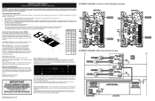
... for more unit-specific details. 15 ELECTRONIC OVEN CONTROL (EOC) RELAY BOARD TEMPERATURE PROBE TEMPERATURE PROBE DOOR SWITCH LOCK SWITCH IMPORTANT DO NOT REMOVE THIS BAG OR DESTROY THE CONTENTS WIRING DIAGRAMS AND SERVICE INFORMATION ENCLOSED REPLACE CONTENTS IN BAG 808532550 REV A EN (2017/06) OVEN LIGHT SPEED BAKE IND MDL SPEED BAKE FAN BAKE BROIL BAKE BROIL L1 L2 OUT L2 IN 1 DLB - Set EOC to do so will not change the Self-Cleaning cycle temperature. Modular Control Systems This appliance...
... for more unit-specific details. 15 ELECTRONIC OVEN CONTROL (EOC) RELAY BOARD TEMPERATURE PROBE TEMPERATURE PROBE DOOR SWITCH LOCK SWITCH IMPORTANT DO NOT REMOVE THIS BAG OR DESTROY THE CONTENTS WIRING DIAGRAMS AND SERVICE INFORMATION ENCLOSED REPLACE CONTENTS IN BAG 808532550 REV A EN (2017/06) OVEN LIGHT SPEED BAKE IND MDL SPEED BAKE FAN BAKE BROIL BAKE BROIL L1 L2 OUT L2 IN 1 DLB - Set EOC to do so will not change the Self-Cleaning cycle temperature. Modular Control Systems This appliance...
Wiring Diagram
Page 3
... WIRING DIAGRAMS AND SERVICE INFORMATION ENCLOSED REPLACE CONTENTS IN BAG Error notification in 1-digit displays. Replacing the ES3000 control* - Induction Controls Wiring/Connections SCHEMATIC DIAGRAM - This service data sheet is equipped with ES3000 and Induction Smoothtop NOTICE - are adequately spaced away from sharp edges, high-temperature components, and moving an appliance remove power cord from electrical outlet, trip circuit breaker to drain static electricity from the use by the ESEC will not operate when a surface element...
... WIRING DIAGRAMS AND SERVICE INFORMATION ENCLOSED REPLACE CONTENTS IN BAG Error notification in 1-digit displays. Replacing the ES3000 control* - Induction Controls Wiring/Connections SCHEMATIC DIAGRAM - This service data sheet is equipped with ES3000 and Induction Smoothtop NOTICE - are adequately spaced away from sharp edges, high-temperature components, and moving an appliance remove power cord from electrical outlet, trip circuit breaker to drain static electricity from the use by the ESEC will not operate when a surface element...

Wiring Diagram
Page 4
... operation Flashing power level Display and pan does not heat. Fluids spilled or object lying on the model number and parts catalog. 2. Steady "Hot surface" indicator light when cooking zone is nothing (water, utensils) in contact with low power. Refer to owners guide for a long time this pan on 261 induction generator board 1. Ensure that induction coil temperature sensor is a listing of window on a smaller cooking zone. Replace if defective or damaged. 3. Clear vent openings...
... operation Flashing power level Display and pan does not heat. Fluids spilled or object lying on the model number and parts catalog. 2. Steady "Hot surface" indicator light when cooking zone is nothing (water, utensils) in contact with low power. Refer to owners guide for a long time this pan on 261 induction generator board 1. Ensure that induction coil temperature sensor is a listing of window on a smaller cooking zone. Replace if defective or damaged. 3. Clear vent openings...
Product Specifications Sheet
Page 2
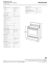
...Handle Design Exterior Finish (Side Panels) Convection System Oven Cleaning System Drawer Functionality OVEN CONTROLS Bake / Broil Effortless™ Convection Conversion Convection Bake / Broil / Roast Quick Bake Convection Quick Preheat Effortless™ Temperature Probe Keep Warm Add-a-Minute Delay Start Self Clean Quick Clean Option Delay Clean Kitchen Timer / Timed Cook Option Auto Oven Shut-Off Oven Lock-Out Lower Drawer Control COOKTOP FEATURES Right Front Element (Watts) Right Rear Element (Watts) Left Front Element (Watts) Left Rear Element (Watts) Hot Surface Indicator Light Element...
...Handle Design Exterior Finish (Side Panels) Convection System Oven Cleaning System Drawer Functionality OVEN CONTROLS Bake / Broil Effortless™ Convection Conversion Convection Bake / Broil / Roast Quick Bake Convection Quick Preheat Effortless™ Temperature Probe Keep Warm Add-a-Minute Delay Start Self Clean Quick Clean Option Delay Clean Kitchen Timer / Timed Cook Option Auto Oven Shut-Off Oven Lock-Out Lower Drawer Control COOKTOP FEATURES Right Front Element (Watts) Right Rear Element (Watts) Left Front Element (Watts) Left Rear Element (Watts) Hot Surface Indicator Light Element...
Product Specifications Sheet
Page 3
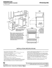
...; Connected Load (kW Rating) @ 240 / 208 Volts = 12.5 / 9.5 kW • Recommended Circuit Breaker - 40 Amps • Always consult local and national electric codes. • Make sure wall coverings around range can withstand heat generated by not less than No. 28 MSG sheet steel, 0.015" stainless steel, 0.024" aluminum or 0.020" copper. 0" clearance is minimum for actual dimensions. 36" (Adjustable to ±1/8") INSTALLATION SPECIFICATIONS...
...; Connected Load (kW Rating) @ 240 / 208 Volts = 12.5 / 9.5 kW • Recommended Circuit Breaker - 40 Amps • Always consult local and national electric codes. • Make sure wall coverings around range can withstand heat generated by not less than No. 28 MSG sheet steel, 0.015" stainless steel, 0.024" aluminum or 0.020" copper. 0" clearance is minimum for actual dimensions. 36" (Adjustable to ±1/8") INSTALLATION SPECIFICATIONS...


