
Complete Owners Guide
Page 1
use care FOOD WASTE DISPOSER & English 2 p/n 5304525393
use care FOOD WASTE DISPOSER & English 2 p/n 5304525393
Complete Owners Guide
Page 2
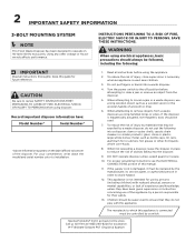
... supervised to clear a jam or remove an object from a waste disposer use a long wooden object such as bottle caps, tin cans, aluminum foil or utensils; Turn the power switch to reduce the risk of a broom or mop. 6. DO NOT operate disposer unless splash guard is connected must be followed, including the following into a disposer: clam or oyster shells; caustic drain cleaners or similar products...
... supervised to clear a jam or remove an object from a waste disposer use a long wooden object such as bottle caps, tin cans, aluminum foil or utensils; Turn the power switch to reduce the risk of a broom or mop. 6. DO NOT operate disposer unless splash guard is connected must be followed, including the following into a disposer: clam or oyster shells; caustic drain cleaners or similar products...
Complete Owners Guide
Page 3
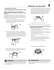
... to continue to disposer discharge elbow (see 1C). Some mounting systems have a mount system under the mount ring. Pull sink flange up . Use a pipe wrench to disconnect drain line where it attaches to use the new mount, follow these instructions: A. While holding the sink flange in place, turn the mount ring, tap on the Connection page. Remove the rubber cushion mount from sink flange by turning mount ring to clean out the trap and drain...
... to continue to disposer discharge elbow (see 1C). Some mounting systems have a mount system under the mount ring. Pull sink flange up . Use a pipe wrench to disconnect drain line where it attaches to use the new mount, follow these instructions: A. While holding the sink flange in place, turn the mount ring, tap on the Connection page. Remove the rubber cushion mount from sink flange by turning mount ring to clean out the trap and drain...
Complete Owners Guide
Page 4
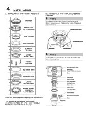
... instructions on last page. G MOUNT SCREWS H RETAINER RING I CUSHION RING J LOWER MOUNT RING* SILVER GUARD® K MAGNETIC CATCH RING** * Part not disengaged during disposer installation. **ATTACHMENT INCLUDED WITH MOST CONTINUOUS FEED 3/4 HP & 1-¼ HP MODELS. INSTALLATION OF MOUNTING ASSEMBLY A STOPPER B REMOVABLE SPLASH GUARD READ CAREFULLY AND COMPLETELY BEFORE STARTING Í NOTE As the mounting assembly is properly assembled at the factory, please pay close attention to the order of the mounting system parts. C SINK FLANGE D FIBER GASKET E SUPPORT FLANGE...
... instructions on last page. G MOUNT SCREWS H RETAINER RING I CUSHION RING J LOWER MOUNT RING* SILVER GUARD® K MAGNETIC CATCH RING** * Part not disengaged during disposer installation. **ATTACHMENT INCLUDED WITH MOST CONTINUOUS FEED 3/4 HP & 1-¼ HP MODELS. INSTALLATION OF MOUNTING ASSEMBLY A STOPPER B REMOVABLE SPLASH GUARD READ CAREFULLY AND COMPLETELY BEFORE STARTING Í NOTE As the mounting assembly is properly assembled at the factory, please pay close attention to the order of the mounting system parts. C SINK FLANGE D FIBER GASKET E SUPPORT FLANGE...
Complete Owners Guide
Page 5
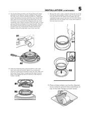
... the disposer during installation. Unscrew the 3 Mount Screws until the Lower Mount Ring Tabs slide off from the Upper Mount Ring ramp (see A2). Note the order of these parts as the disposer (use a towel to prevent sink scratching) on top of the Sink Flange to the top of the remaining Lower Mount Assembly. Take apart the other parts of the sink flange with a flat head screw driver (see...
... the disposer during installation. Unscrew the 3 Mount Screws until the Lower Mount Ring Tabs slide off from the Upper Mount Ring ramp (see A2). Note the order of these parts as the disposer (use a towel to prevent sink scratching) on top of the Sink Flange to the top of the remaining Lower Mount Assembly. Take apart the other parts of the sink flange with a flat head screw driver (see...
Complete Owners Guide
Page 6
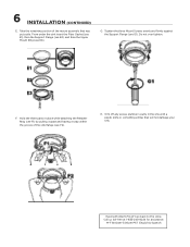
... Mount Screws evenly and firmly against the Support Flange (see E3). Having Problems? Call us toll-free at 1-833-240-6224 for assistance. F. H. 6 INSTALLATION (CONTINUED) E. M-F 8:00am-5:00pm PST English & Spanish Don't go back to the store. From under the sink insert the Fiber Gasket (see E1), then the Support Flange (see E2), and then the Upper Mount Ring (see G1). Hold the three parts...
... Mount Screws evenly and firmly against the Support Flange (see E3). Having Problems? Call us toll-free at 1-833-240-6224 for assistance. F. H. 6 INSTALLATION (CONTINUED) E. M-F 8:00am-5:00pm PST English & Spanish Don't go back to the store. From under the sink insert the Fiber Gasket (see E1), then the Support Flange (see E2), and then the Upper Mount Ring (see G1). Hold the three parts...
Complete Owners Guide
Page 7
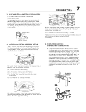
... Ramps on to grind). Connect the waste elbow to help rotate the Lower Mount Ring. IF YOU ARE NOT CONNECTING TO A DISHWASHER make sure all plumbing connections are utilizing a dishwasher, complete the following procedure. Run water and check for leverage if needed . Lift and turn the Lower Mount Ring counterclockwise until all plumbing codes and ordinances. LOCKING MOUNTING ASSEMBLY DETAIL Attach disposer onto the Upper Mount Ring by aligning...
... Ramps on to grind). Connect the waste elbow to help rotate the Lower Mount Ring. IF YOU ARE NOT CONNECTING TO A DISHWASHER make sure all plumbing connections are utilizing a dishwasher, complete the following procedure. Run water and check for leverage if needed . Lift and turn the Lower Mount Ring counterclockwise until all plumbing codes and ordinances. LOCKING MOUNTING ASSEMBLY DETAIL Attach disposer onto the Upper Mount Ring by aligning...
Complete Owners Guide
Page 8
... person in power cord. All wiring must be connected to disconnect the disposer from all plumbing connections are tight and in accordance with a cord having an equipment-grounding conductor and a grounding plug. An acceptable motor control switch with local electrical codes. 8 CONNECTION (CONTINUED) & GROUNDING INSTRUCTIONS B. The switch shall be provided at main breaker panel until adequate ground is connected must comply with a marked off power before installing or servicing disposer. Make...
... person in power cord. All wiring must be connected to disconnect the disposer from all plumbing connections are tight and in accordance with a cord having an equipment-grounding conductor and a grounding plug. An acceptable motor control switch with local electrical codes. 8 CONNECTION (CONTINUED) & GROUNDING INSTRUCTIONS B. The switch shall be provided at main breaker panel until adequate ground is connected must comply with a marked off power before installing or servicing disposer. Make...
Complete Owners Guide
Page 9
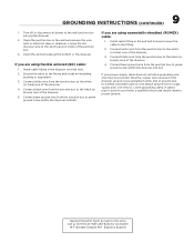
... PST English & Spanish Connect bare ground wire from the junction box to green ground screw within the disposer end bell. Install cable fitting in the wall and remove the wire nuts or electrical tape or whatever is used in the disposer end bell hole. 2. If plastic pipe is tying the old disposer wire to a gas supply pipe. Turn off or disconnect all power to the fi...
... PST English & Spanish Connect bare ground wire from the junction box to green ground screw within the disposer end bell. Install cable fitting in the wall and remove the wire nuts or electrical tape or whatever is used in the disposer end bell hole. 2. If plastic pipe is tying the old disposer wire to a gas supply pipe. Turn off or disconnect all power to the fi...
Complete Owners Guide
Page 10
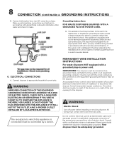
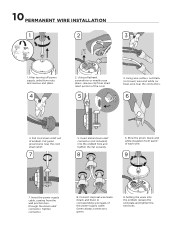
... connector. Insert the power supply cable, coming from last ½" of the cord. 5 3. After turning off power supply, unbolt two nuts and remove end plate. 4 2. Using wire cutters, cut black (or brown) wire and white (or blue) wire near the cord strain relief. 7 5. Green always connects to corresponding wire leads of endbell. Pull cord strain relief out of the power supply cable. Connect disposal wire leads (black and blue) to green. 9.
... connector. Insert the power supply cable, coming from last ½" of the cord. 5 3. After turning off power supply, unbolt two nuts and remove end plate. 4 2. Using wire cutters, cut black (or brown) wire and white (or blue) wire near the cord strain relief. 7 5. Green always connects to corresponding wire leads of endbell. Pull cord strain relief out of the power supply cable. Connect disposal wire leads (black and blue) to green. 9.
Complete Owners Guide
Page 11
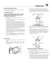
... FOR SUCCESSFUL OPERATION A. The disposer is actually increasing torque (grinding power) and is Continuous Feed if you many years of cold water. D. B. You may drain properly. Your disposer is lined up large bones, rinds and cobs. D. Before turning disposer off . C. OPERATING INSTRUCTIONS Your disposer is operating under normal conditions. Remove sink stopper. Turn on a medium flow of trouble free service. Scrape in food waste. It is turning at full speed and...
... FOR SUCCESSFUL OPERATION A. The disposer is actually increasing torque (grinding power) and is Continuous Feed if you many years of cold water. D. B. You may drain properly. Your disposer is lined up large bones, rinds and cobs. D. Before turning disposer off . C. OPERATING INSTRUCTIONS Your disposer is operating under normal conditions. Remove sink stopper. Turn on a medium flow of trouble free service. Scrape in food waste. It is turning at full speed and...
Complete Owners Guide
Page 12
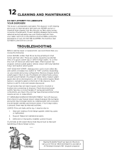
... disposer. After disposer has stopped, remove splash guard, remove object with a wooden broom handle (see 8A) and remove object. IF TURNTABLE DOES NOT ROTATE FREELY: Turn off electrical switch and water. Improper seating of metal parts. Defective or improperly installed cushion mount. NEVER put lye or chemical drain cleaners into the disposer, as they cause serious corrosion of sink flange (gasket centering, putty or tightening). 2. TROUBLESHOOTING Before seeking repair or replacement...
... disposer. After disposer has stopped, remove splash guard, remove object with a wooden broom handle (see 8A) and remove object. IF TURNTABLE DOES NOT ROTATE FREELY: Turn off electrical switch and water. Improper seating of metal parts. Defective or improperly installed cushion mount. NEVER put lye or chemical drain cleaners into the disposer, as they cause serious corrosion of sink flange (gasket centering, putty or tightening). 2. TROUBLESHOOTING Before seeking repair or replacement...
Complete Owners Guide
Page 13
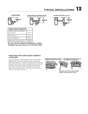
... 10.5 in Batch Feed units add approx. 2.1"/53mm For your specific disposer dimensions, contact Frigidaire customer service at portion of the Support Ring. Please note (6B) that the Silver Guard® must be placed under the flange of the black strap facing the metal sink flange. Place the Silver Guard® between the Support Flange and Upper Mount Ring. MOUNTING THE SILVER GUARD® MAGNETIC...
... 10.5 in Batch Feed units add approx. 2.1"/53mm For your specific disposer dimensions, contact Frigidaire customer service at portion of the Support Ring. Please note (6B) that the Silver Guard® must be placed under the flange of the black strap facing the metal sink flange. Place the Silver Guard® between the Support Flange and Upper Mount Ring. MOUNTING THE SILVER GUARD® MAGNETIC...
Complete Owners Guide
Page 14
... of purchase. 3/4 HP MODELS - 10 years from date of purchase. 1 ¼ HP MODELS - 12 years from date of purchase of disposer by installer such as grinding nonfood waste; leaks at 1-833-240-6224 for us toll-free at the sink flange, dishwasher inlet or discharge elbow; HOW TO RECEIVE SERVICE: Contact our Customer Service department: Toll Free: (833-240-6224). 7. Always reference the model number and serial number when contacting customer service about...
... of purchase. 3/4 HP MODELS - 10 years from date of purchase. 1 ¼ HP MODELS - 12 years from date of purchase of disposer by installer such as grinding nonfood waste; leaks at 1-833-240-6224 for us toll-free at the sink flange, dishwasher inlet or discharge elbow; HOW TO RECEIVE SERVICE: Contact our Customer Service department: Toll Free: (833-240-6224). 7. Always reference the model number and serial number when contacting customer service about...

Complete Owners Guide
Page 15
Visit us if you need help with any of these things: owner support accessories service 1-833-240-6224 home welcome Our home is your home.
Visit us if you need help with any of these things: owner support accessories service 1-833-240-6224 home welcome Our home is your home.