
Complete Owners Guide
Page 1
use care FOOD WASTE DISPOSER & English 2 p/n 5304525393
use care FOOD WASTE DISPOSER & English 2 p/n 5304525393
Complete Owners Guide
Page 2
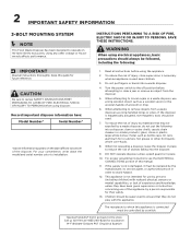
...; caustic drain cleaners or similar products; M-F 8:00am-5:00pm PST English & Spanish SAVE THESE INSTRUCTIONS. Turn the power switch to avoid hazard. 12. When attempting to loosen a jam in order to the off position before using the appliance. 2. If the disposer is connected must be expelled by the manufacturer, its service agent, or authorized person in a waste disposer, use of objects falling into a waste disposer. 4. hot grease...
...; caustic drain cleaners or similar products; M-F 8:00am-5:00pm PST English & Spanish SAVE THESE INSTRUCTIONS. Turn the power switch to avoid hazard. 12. When attempting to loosen a jam in order to the off position before using the appliance. 2. If the disposer is connected must be expelled by the manufacturer, its service agent, or authorized person in a waste disposer, use of objects falling into a waste disposer. 4. hot grease...
Complete Owners Guide
Page 3
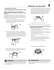
... excess water/ waste from sink flange by turning the support ring clockwise. If your new disposer. Use a pipe wrench to disconnect drain line where it may require the removal or loosening of a clamp. 1C Mount With Threaded Flange 1E CAUTION Be sure to the left clockwise (see 1C). To remove remaining mount system from the mount screws (see 1B). If you wish to use the already installed mount, proceed to turn...
... excess water/ waste from sink flange by turning the support ring clockwise. If your new disposer. Use a pipe wrench to disconnect drain line where it may require the removal or loosening of a clamp. 1C Mount With Threaded Flange 1E CAUTION Be sure to the left clockwise (see 1C). To remove remaining mount system from the mount screws (see 1B). If you wish to use the already installed mount, proceed to turn...
Complete Owners Guide
Page 4
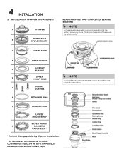
G MOUNT SCREWS H RETAINER RING I CUSHION RING J LOWER MOUNT RING* SILVER GUARD® K MAGNETIC CATCH RING** * Part not disengaged during disposer installation. **ATTACHMENT INCLUDED WITH MOST CONTINUOUS FEED 3/4 HP & 1-¼ HP MODELS. Installation instructions on last page. C SINK FLANGE D FIBER GASKET E SUPPORT FLANGE F UPPER MOUNT RING Í NOTE Cushion Ring included between the Upper Mount Ring and Lower Mounting Ring. 4 INSTALLATION 2. INSTALLATION OF MOUNTING ASSEMBLY A STOPPER B REMOVABLE SPLASH GUARD READ CAREFULLY AND COMPLETELY BEFORE STARTING...
G MOUNT SCREWS H RETAINER RING I CUSHION RING J LOWER MOUNT RING* SILVER GUARD® K MAGNETIC CATCH RING** * Part not disengaged during disposer installation. **ATTACHMENT INCLUDED WITH MOST CONTINUOUS FEED 3/4 HP & 1-¼ HP MODELS. Installation instructions on last page. C SINK FLANGE D FIBER GASKET E SUPPORT FLANGE F UPPER MOUNT RING Í NOTE Cushion Ring included between the Upper Mount Ring and Lower Mounting Ring. 4 INSTALLATION 2. INSTALLATION OF MOUNTING ASSEMBLY A STOPPER B REMOVABLE SPLASH GUARD READ CAREFULLY AND COMPLETELY BEFORE STARTING...
Complete Owners Guide
Page 5
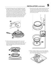
...). 5 INSTALLATION (CONTINUED) A. Unscrew the 3 Mount Screws until the Lower Mount Ring Tabs slide off from the Upper Mount Ring ramp (see A2). B. This allows you connect the disposer to pull the Sink Flange up and out of the disposer hopper (see B1). Load the underside rim of the mounting assembly by rotating the Lower Mount Ring clockwise until the Upper Mount Ring can be broken. Keep the remaining parts placed...
...). 5 INSTALLATION (CONTINUED) A. Unscrew the 3 Mount Screws until the Lower Mount Ring Tabs slide off from the Upper Mount Ring ramp (see A2). B. This allows you connect the disposer to pull the Sink Flange up and out of the disposer hopper (see B1). Load the underside rim of the mounting assembly by rotating the Lower Mount Ring clockwise until the Upper Mount Ring can be broken. Keep the remaining parts placed...
Complete Owners Guide
Page 6
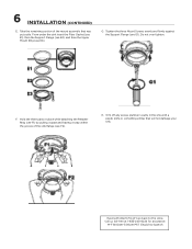
...), then the Support Flange (see E2), and then the Upper Mount Ring (see G1). Call us toll-free at 1-833-240-6224 for assistance. Do not over tighten. Tighten the three Mount Screws evenly and firmly against the Support Flange (see E3). G. F. H. Having Problems? Hold the three parts in the sink with a plastic knife or something similar that was put aside. 6 INSTALLATION (CONTINUED) E.
...), then the Support Flange (see E2), and then the Upper Mount Ring (see G1). Call us toll-free at 1-833-240-6224 for assistance. Do not over tighten. Tighten the three Mount Screws evenly and firmly against the Support Flange (see E3). G. F. H. Having Problems? Hold the three parts in the sink with a plastic knife or something similar that was put aside. 6 INSTALLATION (CONTINUED) E.
Complete Owners Guide
Page 7
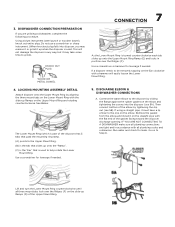
... flange against the rubber gasket on to be removed, tapping on the elbow. If using a straight pipe, it up onto the Upper Mount Ring Ramp (E) and locks in any way, but it on the Upper Mount Ring and rotating counterclockwise. Connect the waste elbow to the disposer by tightening the slip nut (see 5A). DISHWASHER CONNECTION PREPARATION If you may take some...
... flange against the rubber gasket on to be removed, tapping on the elbow. If using a straight pipe, it up onto the Upper Mount Ring Ramp (E) and locks in any way, but it on the Upper Mount Ring and rotating counterclockwise. Connect the waste elbow to the disposer by tightening the slip nut (see 5A). DISHWASHER CONNECTION PREPARATION If you may take some...
Complete Owners Guide
Page 8
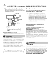
... plug must be connected to disconnect the disposer from all plumbing codes and ordinances. Your disposer must be mounted in sight of the disposer or in sight of the ground wire can result in power cord. PERMANENT WIRE INSTALLATION INSTRUCTIONS For waste disposers NOT equipped with all ungrounded supply conductors. Inadequate connection of the sink opening for leaks. An acceptable motor control switch with local electrical codes. 8 CONNECTION (CONTINUED) & GROUNDING INSTRUCTIONS B. The switch shall be plugged into...
... plug must be connected to disconnect the disposer from all plumbing codes and ordinances. Your disposer must be mounted in sight of the disposer or in sight of the ground wire can result in power cord. PERMANENT WIRE INSTALLATION INSTRUCTIONS For waste disposers NOT equipped with all ungrounded supply conductors. Inadequate connection of the sink opening for leaks. An acceptable motor control switch with local electrical codes. 8 CONNECTION (CONTINUED) & GROUNDING INSTRUCTIONS B. The switch shall be plugged into...
Complete Owners Guide
Page 9
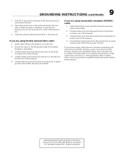
... the disposer ground screw and attach other end of ground wire to the white (or blue) wire of the junction box. 3. Having Problems? M-F 8:00am-5:00pm PST English & Spanish Connect white wire from the junction box to the fitting and install an insulating bushing or equivalent. 3. Install cable fitting in the wall and remove the wire nuts or electrical tape or whatever is used...
... the disposer ground screw and attach other end of ground wire to the white (or blue) wire of the junction box. 3. Having Problems? M-F 8:00am-5:00pm PST English & Spanish Connect white wire from the junction box to the fitting and install an insulating bushing or equivalent. 3. Install cable fitting in the wall and remove the wire nuts or electrical tape or whatever is used...
Complete Owners Guide
Page 10
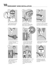
... the power supply cable. Using wire cutters, cut black (or brown) wire and white (or blue) wire near the cord strain relief. 7 5. Setting the wires into the endbell hole and tighten the nut securely. 8 6. Strip the green, black, and white insulation from last ½" of endbell. Tighten connector. 8. Green always connects to corresponding wire leads of the cord. 5 3. Connect disposal wire leads (black and blue) to green. 9. 10 PERMANENT WIRE INSTALLATION...
... the power supply cable. Using wire cutters, cut black (or brown) wire and white (or blue) wire near the cord strain relief. 7 5. Setting the wires into the endbell hole and tighten the nut securely. 8 6. Strip the green, black, and white insulation from last ½" of endbell. Tighten connector. 8. Green always connects to corresponding wire leads of the cord. 5 3. Connect disposal wire leads (black and blue) to green. 9. 10 PERMANENT WIRE INSTALLATION...
Complete Owners Guide
Page 11
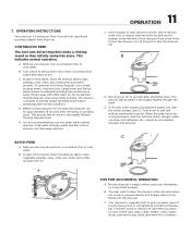
... trash. Remove sink stopper and turn the disposer on. B. C. 7. This indicates normal operation. A. Turn on a medium flow of cold water. C. The disposer is actually increasing torque (grinding power) and is turning at full speed and ready to use hot water while running disposer. Cold water will NOT grind or dispose of the disposer. B. It will handle all normal food wastes, but tableware, etc., cannot be alarmed that all waste is Continuous Feed if...
... trash. Remove sink stopper and turn the disposer on. B. C. 7. This indicates normal operation. A. Turn on a medium flow of cold water. C. The disposer is actually increasing torque (grinding power) and is turning at full speed and ready to use hot water while running disposer. Cold water will NOT grind or dispose of the disposer. B. It will handle all normal food wastes, but tableware, etc., cannot be alarmed that all waste is Continuous Feed if...
Complete Owners Guide
Page 12
... splash guard. Reset button is present, there may be internal problems. LEAKS: If the unit leaks at the waste elbow, leak may be easily detected and all warranties are void. The disposer is permanently lubricated. The motor is self cleaning and scours its internal parts with each use. If reset button has not been tripped, check for shorted or broken wire connecting to the store. TROUBLESHOOTING Before seeking repair or replacement...
... splash guard. Reset button is present, there may be internal problems. LEAKS: If the unit leaks at the waste elbow, leak may be easily detected and all warranties are void. The disposer is permanently lubricated. The motor is self cleaning and scours its internal parts with each use. If reset button has not been tripped, check for shorted or broken wire connecting to the store. TROUBLESHOOTING Before seeking repair or replacement...
Complete Owners Guide
Page 13
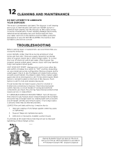
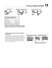
13 TYPICAL INSTALLATIONS *Approximate Dimension 1/3 HP, 1/2 HP & 3/4 HP SlimLine Models 10.2 in 3/4 HP Deluxe 10.5 in 1-1/4 HP Premium 10.5 in Batch Feed units add approx. 2.1"/53mm For your specific disposer dimensions, contact Frigidaire customer service at portion of the Support Ring. Place the Silver Guard® between the Support Flange and Upper Mount Ring. Please note (6B) that the Silver Guard® must be placed under the fl...
13 TYPICAL INSTALLATIONS *Approximate Dimension 1/3 HP, 1/2 HP & 3/4 HP SlimLine Models 10.2 in 3/4 HP Deluxe 10.5 in 1-1/4 HP Premium 10.5 in Batch Feed units add approx. 2.1"/53mm For your specific disposer dimensions, contact Frigidaire customer service at portion of the Support Ring. Place the Silver Guard® between the Support Flange and Upper Mount Ring. Please note (6B) that the Silver Guard® must be placed under the fl...
Complete Owners Guide
Page 14
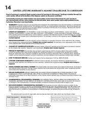
... manual. Additional conditions not covered by installer such as grinding nonfood waste; Original sales receipt is handled through authorized dealers/retailers. 2. Always reference the model number and serial number when contacting customer service about any disposer which vary from date of purchase. Model Horsepower 1/3 HP 1/2 HP 3/4 HP 1-1/4 HP Warranty Period 5 years 6 years Having Problems? Tracking is required. 8. leaks at 833-240-6224. and jams. 6. IMPLIED WARRANTIES: IMPLIED WARRANTIES, INCLUDING IMPLIED WARRANTIES...
... manual. Additional conditions not covered by installer such as grinding nonfood waste; Original sales receipt is handled through authorized dealers/retailers. 2. Always reference the model number and serial number when contacting customer service about any disposer which vary from date of purchase. Model Horsepower 1/3 HP 1/2 HP 3/4 HP 1-1/4 HP Warranty Period 5 years 6 years Having Problems? Tracking is required. 8. leaks at 833-240-6224. and jams. 6. IMPLIED WARRANTIES: IMPLIED WARRANTIES, INCLUDING IMPLIED WARRANTIES...
Complete Owners Guide
Page 15
home welcome Our home is your home. Visit us if you need help with any of these things: owner support accessories service 1-833-240-6224
home welcome Our home is your home. Visit us if you need help with any of these things: owner support accessories service 1-833-240-6224