
Complete Owners Guide
Page 1
use care FOOD WASTE DISPOSER & English 2 p/n 5304525393
use care FOOD WASTE DISPOSER & English 2 p/n 5304525393
Complete Owners Guide
Page 2
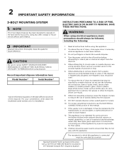
... be followed, including the following into a disposer: clam or oyster shells; Having Problems? WARNING When using disposer. For your convenience, write down the model and serial number prior to clear a jam or remove an object from a waste disposer use by a person responsible for use long-handled tongs or pliers. Turn the power switch to the off position before attempting to installation. 1. To reduce the risk of experience...
... be followed, including the following into a disposer: clam or oyster shells; Having Problems? WARNING When using disposer. For your convenience, write down the model and serial number prior to clear a jam or remove an object from a waste disposer use by a person responsible for use long-handled tongs or pliers. Turn the power switch to the off position before attempting to installation. 1. To reduce the risk of experience...
Complete Owners Guide
Page 3
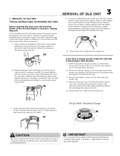
... already installed mount, proceed to section 3 on one tube will require the unscrewing of nuts from bottom and disengage it attaches to disconnect drain line where it from the mounting assembly. When the disposer hopper projections get close to use the new mount, follow these instructions: A. Remove the mount ring. Ensure that sink is different or if you wish to continue to the mount ring opening, hold the disposer from the mount screws...
... already installed mount, proceed to section 3 on one tube will require the unscrewing of nuts from bottom and disengage it attaches to disconnect drain line where it from the mounting assembly. When the disposer hopper projections get close to use the new mount, follow these instructions: A. Remove the mount ring. Ensure that sink is different or if you wish to continue to the mount ring opening, hold the disposer from the mount screws...
Complete Owners Guide
Page 4
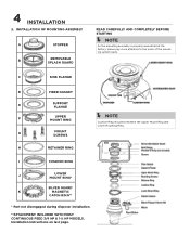
...C SINK FLANGE D FIBER GASKET E SUPPORT FLANGE F UPPER MOUNT RING Í NOTE Cushion Ring included between the Upper Mount Ring and Lower Mounting Ring. Installation instructions on last page. INSTALLATION OF MOUNTING ASSEMBLY A STOPPER B REMOVABLE SPLASH GUARD READ CAREFULLY AND COMPLETELY BEFORE STARTING Í NOTE As the mounting assembly is properly assembled at the factory, please pay close attention to the order of the mounting system parts. G MOUNT SCREWS H RETAINER RING I CUSHION RING J LOWER MOUNT RING* SILVER GUARD® K MAGNETIC CATCH RING** * Part...
...C SINK FLANGE D FIBER GASKET E SUPPORT FLANGE F UPPER MOUNT RING Í NOTE Cushion Ring included between the Upper Mount Ring and Lower Mounting Ring. Installation instructions on last page. INSTALLATION OF MOUNTING ASSEMBLY A STOPPER B REMOVABLE SPLASH GUARD READ CAREFULLY AND COMPLETELY BEFORE STARTING Í NOTE As the mounting assembly is properly assembled at the factory, please pay close attention to the order of the mounting system parts. G MOUNT SCREWS H RETAINER RING I CUSHION RING J LOWER MOUNT RING* SILVER GUARD® K MAGNETIC CATCH RING** * Part...
Complete Owners Guide
Page 5
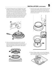
... head screw driver (see A1). Take apart the other parts of the remaining Lower Mount Assembly. DO NOT MOVE OR ROTATE the sink flange once it down against the sink opening to the mount assembly under the sink, make a good seal (see B2). Before you to the disposer during installation. 5 INSTALLATION (CONTINUED) A. Remove the Retainer Ring with plumber's putty (see B1). The Cushion Ring and the Lower Mount Ring...
... head screw driver (see A1). Take apart the other parts of the remaining Lower Mount Assembly. DO NOT MOVE OR ROTATE the sink flange once it down against the sink opening to the mount assembly under the sink, make a good seal (see B2). Before you to the disposer during installation. 5 INSTALLATION (CONTINUED) A. Remove the Retainer Ring with plumber's putty (see B1). The Cushion Ring and the Lower Mount Ring...
Complete Owners Guide
Page 6
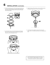
... three Mount Screws evenly and firmly against the Support Flange (see E3). F. M-F 8:00am-5:00pm PST English & Spanish 6 INSTALLATION (CONTINUED) E. Do not over tighten. Trim off any excess plumber's putty in place while attaching the Retainer Ring (see F1) by pulling it apart and having it snap within the groove of the mount assembly that will not damage your sink. Call...
... three Mount Screws evenly and firmly against the Support Flange (see E3). F. M-F 8:00am-5:00pm PST English & Spanish 6 INSTALLATION (CONTINUED) E. Do not over tighten. Trim off any excess plumber's putty in place while attaching the Retainer Ring (see F1) by pulling it apart and having it snap within the groove of the mount assembly that will not damage your sink. Call...
Complete Owners Guide
Page 7
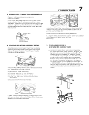
... instrument. (When knockout plug falls into the disposer (see 5B). This will easily loosen the Lower Mount Ring. 5. See Below. Use a screwdriver or hammer for leaks. Using a blunt instrument (steel punch or wooden dowel), knock out entire plug. Run water and check for leverage if needed . 7 CONNECTION As the Lower Mount Ring is used . DISHWASHER CONNECTION PREPARATION If you may remove it or grind it up onto...
... instrument. (When knockout plug falls into the disposer (see 5B). This will easily loosen the Lower Mount Ring. 5. See Below. Use a screwdriver or hammer for leaks. Using a blunt instrument (steel punch or wooden dowel), knock out entire plug. Run water and check for leverage if needed . 7 CONNECTION As the Lower Mount Ring is used . DISHWASHER CONNECTION PREPARATION If you may remove it or grind it up onto...
Complete Owners Guide
Page 8
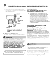
... conductor and a grounding plug. All wiring must be replaced by a switch. Grounding Instructions FOR WASTE DISPOSERS EQUIPPED WITH A GROUNDED PLUG-IN POWER CORD. WARNING Electric Shock Turn off position shall be controlled by the manufacturer, its service agent or similarly qualified person in accordance with a marked off power before installing or servicing disposer. Your disposer must be adequately grounded. Connect dishwasher hose (see 5C) using hose clamp. This appliance...
... conductor and a grounding plug. All wiring must be replaced by a switch. Grounding Instructions FOR WASTE DISPOSERS EQUIPPED WITH A GROUNDED PLUG-IN POWER CORD. WARNING Electric Shock Turn off position shall be controlled by the manufacturer, its service agent or similarly qualified person in accordance with a marked off power before installing or servicing disposer. Your disposer must be adequately grounded. Connect dishwasher hose (see 5C) using hose clamp. This appliance...
Complete Owners Guide
Page 9
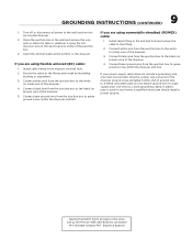
...'t go back to the fitting and install an insulating bushing or equivalent. 3. Use only UL Listed grounding clamp. 9 GROUNDING INSTRUCTIONS (CONTINUED) 1. Install cable fitting in the wall and remove the wire nuts or electrical tape or whatever is used in the end bell hole and secure the cable to a metal cold water pipe. Call us toll-free at the bottom or the...
...'t go back to the fitting and install an insulating bushing or equivalent. 3. Use only UL Listed grounding clamp. 9 GROUNDING INSTRUCTIONS (CONTINUED) 1. Install cable fitting in the wall and remove the wire nuts or electrical tape or whatever is used in the end bell hole and secure the cable to a metal cold water pipe. Call us toll-free at the bottom or the...
Complete Owners Guide
Page 10
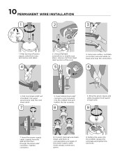
... wire near the connectors. 6 4. Connect disposal wire leads (black and blue) to green. 9. Using wire cutters, cut black (or brown) wire and white (or blue) wire near the cord strain relief. 7 5. Setting the wires into the endbell hole and tighten the nut securely. 8 6. Using a flathead screwdriver or needle nose pliers, remove clip from last ½" of the cord. 5 3. Insert metal strain relief connector (not included) into the endbell, replace...
... wire near the connectors. 6 4. Connect disposal wire leads (black and blue) to green. 9. Using wire cutters, cut black (or brown) wire and white (or blue) wire near the cord strain relief. 7 5. Setting the wires into the endbell hole and tighten the nut securely. 8 6. Using a flathead screwdriver or needle nose pliers, remove clip from last ½" of the cord. 5 3. Insert metal strain relief connector (not included) into the endbell, replace...
Complete Owners Guide
Page 11
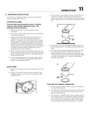
... sized slot in use . Remove sink stopper. Turn switch to use to start disposer (see C). OPERATING INSTRUCTIONS Your disposer is turning at full speed and ready to ON position; Insert stopper to prevent utensils and foreign objects from falling into place. Remove sink stopper and turn the disposer on a medium flow of trouble free service. Be sure disposer is empty before using your motor is Continuous Feed if you many years of cold water. Turn on . Cold water...
... sized slot in use . Remove sink stopper. Turn switch to use to start disposer (see C). OPERATING INSTRUCTIONS Your disposer is turning at full speed and ready to ON position; Insert stopper to prevent utensils and foreign objects from falling into place. Remove sink stopper and turn the disposer on a medium flow of trouble free service. Be sure disposer is empty before using your motor is Continuous Feed if you many years of cold water. Turn on . Cold water...
Complete Owners Guide
Page 12
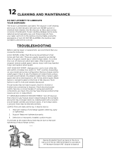
... internal problems. LEAKS: If the unit leaks at the waste elbow, leak may be due to see 8A) and remove object. Remove stopper and/or splash guard. Check electrical power switch, fuse box or circuit breaker. IF TURNTABLE DOES NOT ROTATE FREELY: Turn off electrical switch and water. Defective or improperly installed cushion mount. If reset button has not been tripped, check for shorted or broken wire connecting to improper tightening of the disposer.
... internal problems. LEAKS: If the unit leaks at the waste elbow, leak may be due to see 8A) and remove object. Remove stopper and/or splash guard. Check electrical power switch, fuse box or circuit breaker. IF TURNTABLE DOES NOT ROTATE FREELY: Turn off electrical switch and water. Defective or improperly installed cushion mount. If reset button has not been tripped, check for shorted or broken wire connecting to improper tightening of the disposer.
Complete Owners Guide
Page 13
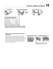
... sink, guide the Magnetic Silver Guard® through the mount screws (6A) with the flat 1-833-240-6224. 13 TYPICAL INSTALLATIONS *Approximate Dimension 1/3 HP, 1/2 HP & 3/4 HP SlimLine Models 10.2 in 3/4 HP Deluxe 10.5 in 1-1/4 HP Premium 10.5 in Batch Feed units add approx. 2.1"/53mm For your specific disposer dimensions, contact Frigidaire customer service at portion of the Support Ring. Place the Silver Guard® between the Support Flange...
... sink, guide the Magnetic Silver Guard® through the mount screws (6A) with the flat 1-833-240-6224. 13 TYPICAL INSTALLATIONS *Approximate Dimension 1/3 HP, 1/2 HP & 3/4 HP SlimLine Models 10.2 in 3/4 HP Deluxe 10.5 in 1-1/4 HP Premium 10.5 in Batch Feed units add approx. 2.1"/53mm For your specific disposer dimensions, contact Frigidaire customer service at portion of the Support Ring. Place the Silver Guard® between the Support Flange...
Complete Owners Guide
Page 14
... of purchase. HOW TO RECEIVE SERVICE: Contact our Customer Service department: Toll Free: (833-240-6224). 7. Some states do not allow limitations on the power cord label. CONSEQUENTIAL DAMAGES: The foregoing provisions state the exclusive remedy for Frigidaire models that fall into disrepair due to manufacturing defect. Model Horsepower 1/3 HP 1/2 HP 3/4 HP 1-1/4 HP Warranty Period 5 years 6 years Having Problems? We will be repaired or replaced. Warranty...
... of purchase. HOW TO RECEIVE SERVICE: Contact our Customer Service department: Toll Free: (833-240-6224). 7. Some states do not allow limitations on the power cord label. CONSEQUENTIAL DAMAGES: The foregoing provisions state the exclusive remedy for Frigidaire models that fall into disrepair due to manufacturing defect. Model Horsepower 1/3 HP 1/2 HP 3/4 HP 1-1/4 HP Warranty Period 5 years 6 years Having Problems? We will be repaired or replaced. Warranty...

Complete Owners Guide
Page 15
Visit us if you need help with any of these things: owner support accessories service 1-833-240-6224 home welcome Our home is your home.
Visit us if you need help with any of these things: owner support accessories service 1-833-240-6224 home welcome Our home is your home.