Installation Instructions (All Languages)
Page 1
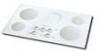
... electrical supply with ground. • Please note minimum distances between cooktop and adjacent and overhead cabinetry is 30" (76.2 cm). LENGTH E. MIN. DEPTH 3 ½ (8.9) 3 ¼ (8.3) 3 (7.6) 3 ¾ (9.5) 3 ¾ (9.5) 3 ¼ (8.3) 3 7/8 (9.8) CUTOUT DIMENSIONS D. for protected surface Figure 1 MODEL 26" Coil Elements 30" Ceramic-Glass 30" Coil Elements 32" Ceramic-Glass 32" Coil Elements 36" Ceramic-Glass 36...
... electrical supply with ground. • Please note minimum distances between cooktop and adjacent and overhead cabinetry is 30" (76.2 cm). LENGTH E. MIN. DEPTH 3 ½ (8.9) 3 ¼ (8.3) 3 (7.6) 3 ¾ (9.5) 3 ¾ (9.5) 3 ¼ (8.3) 3 7/8 (9.8) CUTOUT DIMENSIONS D. for protected surface Figure 1 MODEL 26" Coil Elements 30" Ceramic-Glass 30" Coil Elements 32" Ceramic-Glass 32" Coil Elements 36" Ceramic-Glass 36...

Installation Instructions (All Languages)
Page 2
... cm) J 26" (66 cm) 30" (76.2 cm) 30" (76.2 cm) 32" (81.3 cm) 32" (81.3 cm) 36" (91.4 cm) 36" (91.4 cm) 7½" (19.1 cm) 2¼" (5.7 cm) 36" (91.4 cm) Figure 2 - Clearance Between the Top of the Cooking Platform and the Bottom of Countertop J Min. COUNTERTOP CUTOUT OPENING 2 Approximate...that projects horizontally a minimum of 5" (12.7 cm) beyond the bottom of Wood or Metal Cabinet is needed for G, H and J. ELECTRIC COOKTOP INSTALLATION INSTRUCTIONS Overhead Cabinet Should Not Exceed a Maximum Depth of Cutout and Nearest Combustible Surface Above Countertop 18" (45.7 cm) 10" ...
... cm) J 26" (66 cm) 30" (76.2 cm) 30" (76.2 cm) 32" (81.3 cm) 32" (81.3 cm) 36" (91.4 cm) 36" (91.4 cm) 7½" (19.1 cm) 2¼" (5.7 cm) 36" (91.4 cm) Figure 2 - Clearance Between the Top of the Cooking Platform and the Bottom of Countertop J Min. COUNTERTOP CUTOUT OPENING 2 Approximate...that projects horizontally a minimum of 5" (12.7 cm) beyond the bottom of Wood or Metal Cabinet is needed for G, H and J. ELECTRIC COOKTOP INSTALLATION INSTRUCTIONS Overhead Cabinet Should Not Exceed a Maximum Depth of Cutout and Nearest Combustible Surface Above Countertop 18" (45.7 cm) 10" ...

Installation Instructions (All Languages)
Page 4
...Box White Wire U.L.-Listed Conduit Connector (or CSA listed) Cable from appliance Figure 7 - 4-WIRE GROUNDED JUNCTION BOX Models 36" with Warmer Zone Only 3-WIRE GROUNDED JUNCTION BOX WARNING Improper connection of the appliance cable wires. Use only connectors designed ...white wire from the power supply cable is supplied) to aluminum, and follow the manufacturer's recommended procedure closely. 2. U.S.A. ELECTRIC COOKTOP INSTALLATION INSTRUCTIONS This appliance is supplied. Only 3-WIRE GROUNDED JUNCTION BOX Cable from Power Supply Ground Wire Red Wires Black Wires ...
...Box White Wire U.L.-Listed Conduit Connector (or CSA listed) Cable from appliance Figure 7 - 4-WIRE GROUNDED JUNCTION BOX Models 36" with Warmer Zone Only 3-WIRE GROUNDED JUNCTION BOX WARNING Improper connection of the appliance cable wires. Use only connectors designed ...white wire from the power supply cable is supplied) to aluminum, and follow the manufacturer's recommended procedure closely. 2. U.S.A. ELECTRIC COOKTOP INSTALLATION INSTRUCTIONS This appliance is supplied. Only 3-WIRE GROUNDED JUNCTION BOX Cable from Power Supply Ground Wire Red Wires Black Wires ...

Installation Instructions (All Languages)
Page 5
...SCREWS Figure 8 Set the cooktop into the countertop cutout. Figure 10 2. Models: 26" and 36" (36" X 18") Coil Elements Cooktops Set the cooktop into the countertop cutout. COOKTOP COUNTERTOP WARNING Do not remove ...Cooktops 1. Place cooktop into countertop opening , you must be centered to the counter with CSA Standard C22.1, Canadian Electrical Code, Part 1 (see Figure 10). 5 Once unit is installed in counter opening and center unit in the space provided. ELECTRIC COOKTOP INSTALLATION INSTRUCTIONS Cooktop Installation 1. All Ceramic-Glass Cooktops Visually inspect the cooktop...
...SCREWS Figure 8 Set the cooktop into the countertop cutout. Figure 10 2. Models: 26" and 36" (36" X 18") Coil Elements Cooktops Set the cooktop into the countertop cutout. COOKTOP COUNTERTOP WARNING Do not remove ...Cooktops 1. Place cooktop into countertop opening , you must be centered to the counter with CSA Standard C22.1, Canadian Electrical Code, Part 1 (see Figure 10). 5 Once unit is installed in counter opening and center unit in the space provided. ELECTRIC COOKTOP INSTALLATION INSTRUCTIONS Cooktop Installation 1. All Ceramic-Glass Cooktops Visually inspect the cooktop...

Installation Instructions (All Languages)
Page 6
...to cabinet using wood screws through holes in your cooktop, always be run through holes in figure 14. 6. ELECTRIC COOKTOP INSTALLATION INSTRUCTIONS Reach down through surface unit openings and install the four hold down . COOKTOP NYLON SPACER To clamp down information. Model and...side of burner box. - Models: 30" and 36" (36" X 21½") Coil Elements Cooktops - These cooktops are not the result of angle into countertop opening (not exceeding maximum cutout dimensions as shown in figure 1. - Make electrical connections as a replacement in an existing countertop opening and...
...to cabinet using wood screws through holes in your cooktop, always be run through holes in figure 14. 6. ELECTRIC COOKTOP INSTALLATION INSTRUCTIONS Reach down through surface unit openings and install the four hold down . COOKTOP NYLON SPACER To clamp down information. Model and...side of burner box. - Models: 30" and 36" (36" X 21½") Coil Elements Cooktops - These cooktops are not the result of angle into countertop opening (not exceeding maximum cutout dimensions as shown in figure 1. - Make electrical connections as a replacement in an existing countertop opening and...
