
Installation Instructions
Page 1
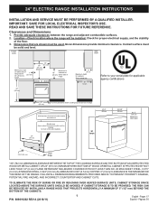
... BY REACHING OVER HEATED SURFACE UNITS, CABINET STORAGE SPACE LOCATED ABOVE THE SURFACE UNITS SHOULD BE AVOIDED. IMPORTANT: SAVE FOR LOCAL ELECTRICAL INSPECTOR'S USE. Contact surface must be installed for proper electrical supply, and the stability of the floor. 3. FOLLOW ALL DIMENSION REQUIREMENTS PROVIDED ABOVE TO PREVENT PROPERTY DAMAGE, POTENTIAL FIRE HAZARD, AND INCORRECT COUNTERTOP AND CABINET CUTS. 24" ELECTRIC RANGE INSTALLATION INSTRUCTIONS INSTALLATION AND SERVICE MUST BE PERFORMED...
... BY REACHING OVER HEATED SURFACE UNITS, CABINET STORAGE SPACE LOCATED ABOVE THE SURFACE UNITS SHOULD BE AVOIDED. IMPORTANT: SAVE FOR LOCAL ELECTRICAL INSPECTOR'S USE. Contact surface must be installed for proper electrical supply, and the stability of the floor. 3. FOLLOW ALL DIMENSION REQUIREMENTS PROVIDED ABOVE TO PREVENT PROPERTY DAMAGE, POTENTIAL FIRE HAZARD, AND INCORRECT COUNTERTOP AND CABINET CUTS. 24" ELECTRIC RANGE INSTALLATION INSTRUCTIONS INSTALLATION AND SERVICE MUST BE PERFORMED...
Installation Instructions
Page 2
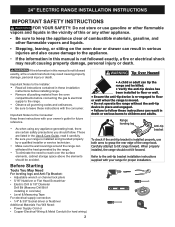
... anti-tip bracket installation instructions supplied with the consumer. Before Starting Tools You May Need For leveling legs and Anti-Tip Bracket: • Adjustable wrench or channel lock pliers • 5/16" Nutdriver or Flat Head Screwdriver • Electric Drill & 1/8" Diameter Drill Bit (Masonry Drill Bit if installing in concrete) • Level & Measuring Tape For electrical supply connection: • 1/4" & 3/8" Socket driver or Nutdriver Additional Materials You Will Need: • Power Supply Cord or • Copper Electrical Wiring...
... anti-tip bracket installation instructions supplied with the consumer. Before Starting Tools You May Need For leveling legs and Anti-Tip Bracket: • Adjustable wrench or channel lock pliers • 5/16" Nutdriver or Flat Head Screwdriver • Electric Drill & 1/8" Diameter Drill Bit (Masonry Drill Bit if installing in concrete) • Level & Measuring Tape For electrical supply connection: • 1/4" & 3/8" Socket driver or Nutdriver Additional Materials You Will Need: • Power Supply Cord or • Copper Electrical Wiring...
Installation Instructions
Page 3
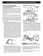
... Pilot Holes and Fasten Bracket - latest edition -- Electrical Connection Requirements Avoid fire hazard or electrical shock. If molding is installed and does not allow room for installation in wall. Place bracket on an open door or if a child climbs upon it forward. Use the information below to the floor. and Local Electrical Code requirements. When fastening to the floor by adjusting the (4) leveling legs with the range. Anti-Tip Bracket Installation Instructions Important...
... Pilot Holes and Fasten Bracket - latest edition -- Electrical Connection Requirements Avoid fire hazard or electrical shock. If molding is installed and does not allow room for installation in wall. Place bracket on an open door or if a child climbs upon it forward. Use the information below to the floor. and Local Electrical Code requirements. When fastening to the floor by adjusting the (4) leveling legs with the range. Anti-Tip Bracket Installation Instructions Important...
Installation Instructions
Page 4
... usual manner. 4 and local electrical code requirements. NOTE: Electric slide-in connection to the connection block located behind the back panel access cover. For mobile homes, new installation or recreational vehicles, use copper wire in range is required on end of a power supply cord kit. Excess wire in Canada; hole as instructed under "Permanent Wire Connections" in accordance with upturned ends. If used , a 50A power cord must be connected to a grounded, metallic, permanent wiring system, or a grounding connector...
... usual manner. 4 and local electrical code requirements. NOTE: Electric slide-in connection to the connection block located behind the back panel access cover. For mobile homes, new installation or recreational vehicles, use copper wire in range is required on end of a power supply cord kit. Excess wire in Canada; hole as instructed under "Permanent Wire Connections" in accordance with upturned ends. If used , a 50A power cord must be connected to a grounded, metallic, permanent wiring system, or a grounding connector...
Installation Instructions
Page 5
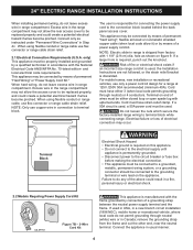
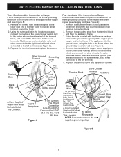
... power supply cord (see Figure 8). 3. Cord Kit Hole. Figure 8 Black Wire 1 1/8" (2.9cm) Dia. Direct Connection Hole. Ground (Bare Copper Wire) Neutral (White Wire) A User Supplied Strain-relief Must Be Installed at the lower right end of the rear cover to the outer terminals. Replace the terminal cover and replace the screws. Replace the terminal cover and replace the screws. Cord Kit Hole. Match wires and terminals by color (red wires connected to the right terminal, black wires connected...
... power supply cord (see Figure 8). 3. Cord Kit Hole. Figure 8 Black Wire 1 1/8" (2.9cm) Dia. Direct Connection Hole. Ground (Bare Copper Wire) Neutral (White Wire) A User Supplied Strain-relief Must Be Installed at the lower right end of the rear cover to the outer terminals. Replace the terminal cover and replace the screws. Replace the terminal cover and replace the screws. Cord Kit Hole. Match wires and terminals by color (red wires connected to the right terminal, black wires connected...
Installation Instructions
Page 6
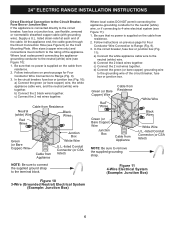
... breaker, fuse box or junction box, use flexible, armored or nonmetallic sheathed copper cable (with grounding wire). 24" ELECTRIC RANGE INSTALLATION INSTRUCTIONS Direct Electrical Connection to the Circuit Breaker, Fuse Box or Junction Box If the appliance is connected directly to the neutral (white) wire. Supply a U.L. listed strain-relief at each end of the appliance. c) Connect the 2 red wires together. Follow instructions on previous page for Four Conductor Wire Connection to the grounding wire...
... breaker, fuse box or junction box, use flexible, armored or nonmetallic sheathed copper cable (with grounding wire). 24" ELECTRIC RANGE INSTALLATION INSTRUCTIONS Direct Electrical Connection to the Circuit Breaker, Fuse Box or Junction Box If the appliance is connected directly to the neutral (white) wire. Supply a U.L. listed strain-relief at each end of the appliance. c) Connect the 2 red wires together. Follow instructions on previous page for Four Conductor Wire Connection to the grounding wire...
Installation Instructions
Page 7
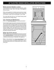
... operating instruction sections in your Use & Care Manual for servicing and cleaning. The list includes common occurrences that are located on the oven front frame, visible when the door is open, and on your range. Please call or write if you have inquiries about your range, always be sure to include the model and serial numbers and a lot number or letter from the wall. 24" ELECTRIC RANGE INSTALLATION INSTRUCTIONS Model and Serial Number Location The serial plates...
... operating instruction sections in your Use & Care Manual for servicing and cleaning. The list includes common occurrences that are located on the oven front frame, visible when the door is open, and on your range. Please call or write if you have inquiries about your range, always be sure to include the model and serial numbers and a lot number or letter from the wall. 24" ELECTRIC RANGE INSTALLATION INSTRUCTIONS Model and Serial Number Location The serial plates...


