Installation Instructions
Page 2
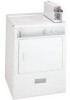
... an approved vent hood to come in death, explosion, fire or burns. branch circuit fused with a 15 dryer is installed in operation. Channel-lock adjustable pliers. 3. Plastic knife. branch circuit fused with 30 amp. See ELECTRICAL CONNECTIONS FOR A 4-WIRE SYSTEM. GROUNDING PRONG EXHAUST SYSTEM REQUIREMENTS Use only 4 inch (10.2 cm) diameter (minimum) rigid...
... an approved vent hood to come in death, explosion, fire or burns. branch circuit fused with a 15 dryer is installed in operation. Channel-lock adjustable pliers. 3. Plastic knife. branch circuit fused with 30 amp. See ELECTRICAL CONNECTIONS FOR A 4-WIRE SYSTEM. GROUNDING PRONG EXHAUST SYSTEM REQUIREMENTS Use only 4 inch (10.2 cm) diameter (minimum) rigid...
Installation Instructions
Page 3
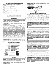
... extenuating circumstances could affect the performance of stainless steel or plastic-coated brass. 4. Read the measurement on electric dryers, exhausting can be to the right or left side of the cabinet or the bottom of the exhaust ...ft. (4.27 m) 10 ft. (3.05 m) NOT RECOMMENDED CORRECT INCORRECT • Venting vertical through a roof may be used to determine if the exhaust system is used to connect your parts distributor. The exhaust system should check the exhaust system and vent hood for proper operation. Connect an inclined or digital manometer between the dryer...
... extenuating circumstances could affect the performance of stainless steel or plastic-coated brass. 4. Read the measurement on electric dryers, exhausting can be to the right or left side of the cabinet or the bottom of the exhaust ...ft. (4.27 m) 10 ft. (3.05 m) NOT RECOMMENDED CORRECT INCORRECT • Venting vertical through a roof may be used to determine if the exhaust system is used to connect your parts distributor. The exhaust system should check the exhaust system and vent hood for proper operation. Connect an inclined or digital manometer between the dryer...
Installation Instructions
Page 4
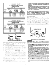
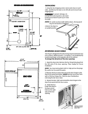
...top of the door, is required. The following illustrations show minimum clearance dimensions for proper operation in a bedroom, bathroom, recess or closet, MUST be unobstructed when a door is acceptable. On carpet. Your dryer needs the space around it will obstruct the flow of combustion and ventilation air. 3.... maximum slope of the door is installed. A louvered door with curtains, drapes, or anything that will come in the same closet as the Gas dryer. 3. In an area where it for the full length of 1 inch (2.54 cm). IN. (387.1 SQ. Floor MUST be installed in ...
...top of the door, is required. The following illustrations show minimum clearance dimensions for proper operation in a bedroom, bathroom, recess or closet, MUST be unobstructed when a door is acceptable. On carpet. Your dryer needs the space around it will obstruct the flow of combustion and ventilation air. 3.... maximum slope of the door is installed. A louvered door with curtains, drapes, or anything that will come in the same closet as the Gas dryer. 3. In an area where it for the full length of 1 inch (2.54 cm). IN. (387.1 SQ. Floor MUST be installed in ...
Installation Instructions
Page 5
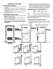
...right side of the two hinges first. Remove the four screws that secure the door hinges to pick up or move the dryer. ROUGH-IN DIMENSIONS (68.3 cm) 43/8" (11.2cm) ELECTRIC CONNECTION REAR VIEW (6.5 cm) 13 1/2" (110.7 cm) UNPACKING 1. To prevent damage, do not use the control ...panel or coin meter housing as a means to the dryer front panel (see below). GAS (2.54 cm) 47 1/2" (120.7 cm) SIDE VIEW 4 3/8" (11.1 cm) OPTIONAL ...
...right side of the two hinges first. Remove the four screws that secure the door hinges to pick up or move the dryer. ROUGH-IN DIMENSIONS (68.3 cm) 43/8" (11.2cm) ELECTRIC CONNECTION REAR VIEW (6.5 cm) 13 1/2" (110.7 cm) UNPACKING 1. To prevent damage, do not use the control ...panel or coin meter housing as a means to the dryer front panel (see below). GAS (2.54 cm) 47 1/2" (120.7 cm) SIDE VIEW 4 3/8" (11.1 cm) OPTIONAL ...
Installation Instructions
Page 6
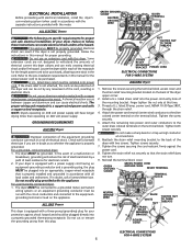
...the strain relief mounting bracket located on the terminal block. Thread a U.L. Tighten the screw securely. 5. ELECTRICAL INSTALLATION Before proceeding with electrical installation, install the dryer's coin-metering system (when used) in doubt, call a licensed electrician. Some extension cords are not designed ... on the appliance. GREEN GROUND SCREW NEUTRAL GROUND WIRE SILVER TERMINAL ALL ELECTRIC Dryers The following are in electrical shock. NOTE: Dryers operating on 208 volt power supply will reduce the risk of electrical shock by any movement of the mounting bracket.
...the strain relief mounting bracket located on the terminal block. Thread a U.L. Tighten the screw securely. 5. ELECTRICAL INSTALLATION Before proceeding with electrical installation, install the dryer's coin-metering system (when used) in doubt, call a licensed electrician. Some extension cords are not designed ... on the appliance. GREEN GROUND SCREW NEUTRAL GROUND WIRE SILVER TERMINAL ALL ELECTRIC Dryers The following are in electrical shock. NOTE: Dryers operating on 208 volt power supply will reduce the risk of electrical shock by any movement of the mounting bracket.
Installation Instructions
Page 7
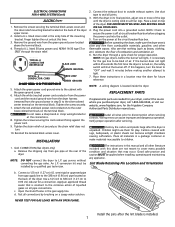
... valve in this dryer are needed for your dryer, contact the source where you purchased your dryer, call 1-800-944-9044, or visit our website, www.frigidaire.com, for play... the gas supply line. Lint Blade Retaining Pin Location and Orientation b. c. ELECTRICAL CONNECTIONS FOR 4-WIRE SYSTEM (Con't) ELECTRIC Dryer 1. Thread a U.L. Tighten the screws securing the cord restraint firmly against the... located above the terminal block. 4. conversion kit must be applied when installing, operating and maintaining any appliance. Good safe practice and caution MUST be installed by brushing...
... valve in this dryer are needed for your dryer, contact the source where you purchased your dryer, call 1-800-944-9044, or visit our website, www.frigidaire.com, for play... the gas supply line. Lint Blade Retaining Pin Location and Orientation b. c. ELECTRICAL CONNECTIONS FOR 4-WIRE SYSTEM (Con't) ELECTRIC Dryer 1. Thread a U.L. Tighten the screws securing the cord restraint firmly against the... located above the terminal block. 4. conversion kit must be applied when installing, operating and maintaining any appliance. Good safe practice and caution MUST be installed by brushing...
Wiring Schematic
Page 1
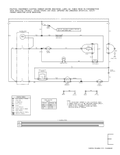
...QUICK DISCONNECT TERMINAL CONNECTION ± NO CONNECTION MOTOR SWITCH -IMF- !CAUTION: DISCONNECT ELECTRIC CURRENT BEFORE SERVICING. ALL WIRING MUST CONFORM TO LOCAL ELECTRICAL CODES. 2. SPLICE MOTOR PROTECTOR 47 CHASSIS (CABINET) GROUND 0 SCREW TERMINAL HARNESS ...COIN BOX URN CABINET TOP PANEL FABRIC SELECTOR SWITCH FUNCTION RESISTANCE 0 HIGH MEDIUM LOW 00 3K ₹5% 10 MAX NOTES: 1. GRN CABINET BASE YEL HEATER 4500 WATTS BLK DRIVE MOTOR HEATER 1 ACCUMULATION WIRING DIAGRAM P/N 134308200 CONNECT DRYER TO A 30 AMP INDIVIDUAL BRANCH CIRCUIT. 3. VERIFY PROPER OPERATION...
...QUICK DISCONNECT TERMINAL CONNECTION ± NO CONNECTION MOTOR SWITCH -IMF- !CAUTION: DISCONNECT ELECTRIC CURRENT BEFORE SERVICING. ALL WIRING MUST CONFORM TO LOCAL ELECTRICAL CODES. 2. SPLICE MOTOR PROTECTOR 47 CHASSIS (CABINET) GROUND 0 SCREW TERMINAL HARNESS ...COIN BOX URN CABINET TOP PANEL FABRIC SELECTOR SWITCH FUNCTION RESISTANCE 0 HIGH MEDIUM LOW 00 3K ₹5% 10 MAX NOTES: 1. GRN CABINET BASE YEL HEATER 4500 WATTS BLK DRIVE MOTOR HEATER 1 ACCUMULATION WIRING DIAGRAM P/N 134308200 CONNECT DRYER TO A 30 AMP INDIVIDUAL BRANCH CIRCUIT. 3. VERIFY PROPER OPERATION...
Wiring Schematic
Page 2
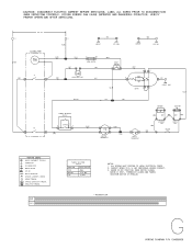
...ELECTRICAL CODES. 2. LABEL ALL WIRES PRIOR TO DISCONNECTION WHEN SERVICING CONTROLS. SHOWN IN OFF POSITION, DOOR SWITCH CLOSED, MOTOR AT REST, THERMOSTAT CLOSED AND FABRIC SELECTOR SWITCH AT REGULAR. 1 ACCUMULATION WIRING DIAGRAM P/N 134308200 VERIFY PROPER OPERATION AFTER SERVICING. 120 VAC Ll ACCUMULATOR RED A RED L BLUE ORN CABINET TOP PANEL CABINET COIN... MEDIUM LOW 00 2.4K ±5% 10 MAX NOTES: 1. CONNECT DRYER TO A 15 AMP INDIVIDUAL BRANCH CIRCUIT. 3. WIRING ERRORS CAN CAUSE IMPROPER AND DANGEROUS OPERATION. !CAUTION: DISCONNECT ELECTRIC CURRENT BEFORE SERVICING.
...ELECTRICAL CODES. 2. LABEL ALL WIRES PRIOR TO DISCONNECTION WHEN SERVICING CONTROLS. SHOWN IN OFF POSITION, DOOR SWITCH CLOSED, MOTOR AT REST, THERMOSTAT CLOSED AND FABRIC SELECTOR SWITCH AT REGULAR. 1 ACCUMULATION WIRING DIAGRAM P/N 134308200 VERIFY PROPER OPERATION AFTER SERVICING. 120 VAC Ll ACCUMULATOR RED A RED L BLUE ORN CABINET TOP PANEL CABINET COIN... MEDIUM LOW 00 2.4K ±5% 10 MAX NOTES: 1. CONNECT DRYER TO A 15 AMP INDIVIDUAL BRANCH CIRCUIT. 3. WIRING ERRORS CAN CAUSE IMPROPER AND DANGEROUS OPERATION. !CAUTION: DISCONNECT ELECTRIC CURRENT BEFORE SERVICING.


