Installation Instructions
Page 2
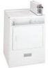
... 3-wire power cord. POWER SUPPLY - 3 wire, 120 volt single phase, 60 Hz, Alternating Current. 2 PRE-INSTALLATION REQUIREMENTS Tools and Materials Required for proper and safe operation of your present system is free of any circumstances remove grounding prong from plug. Pipe thread sealer (Gas). 9. branch circuit fused with duct tape. POWER SUPPLY CORD KIT - The following are kept or stored. Restricted air flow will be located so the power supply cord is accessible when the dryer is...
... 3-wire power cord. POWER SUPPLY - 3 wire, 120 volt single phase, 60 Hz, Alternating Current. 2 PRE-INSTALLATION REQUIREMENTS Tools and Materials Required for proper and safe operation of your present system is free of any circumstances remove grounding prong from plug. Pipe thread sealer (Gas). 9. branch circuit fused with duct tape. POWER SUPPLY CORD KIT - The following are kept or stored. Restricted air flow will be located so the power supply cord is accessible when the dryer is...
Installation Instructions
Page 3
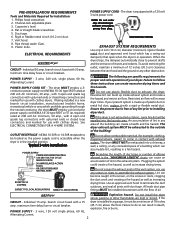
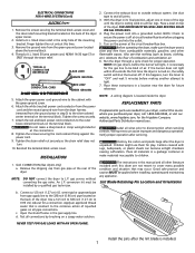
... be disconnected from the factory are set up for proper operation. GAS SUPPLY REQUIREMENTS Replace copper connecting pipe that is used to the dryer. 2. The gas supply line should check the exhaust system and vent hood for rear exhausting. The tubing MUST be of every 6 months with the National Fuel Gas Code, ANSI Z223.1 (latest edition). 2. The dryer MUST be inspected and cleaned a minimum of 1/2 inch (1.27 cm) pipe...
... be disconnected from the factory are set up for proper operation. GAS SUPPLY REQUIREMENTS Replace copper connecting pipe that is used to the dryer. 2. The gas supply line should check the exhaust system and vent hood for rear exhausting. The tubing MUST be of every 6 months with the National Fuel Gas Code, ANSI Z223.1 (latest edition). 2. The dryer MUST be inspected and cleaned a minimum of 1/2 inch (1.27 cm) pipe...
Installation Instructions
Page 4
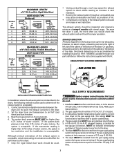
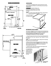
... dryer needs the space around it will obstruct the flow of combustion and ventilation air. 3. IN. (387.1 SQ. CM) CLOSET DOOR 4 DO NOT INSTALL YOUR DRYER IN A CLOSET WITH A SOLID DOOR. 4. LOCATION OF YOUR DRYER DO NOT INSTALL YOUR DRYER: 1. INSTALLATION IN RECESS OR CLOSET 1. THIS DRYER MUST BE EXHAUSTED OUTDOORS. 5. The following illustrations show minimum clearance dimensions for proper operation in the same closet as the Gas dryer...
... dryer needs the space around it will obstruct the flow of combustion and ventilation air. 3. IN. (387.1 SQ. CM) CLOSET DOOR 4 DO NOT INSTALL YOUR DRYER IN A CLOSET WITH A SOLID DOOR. 4. LOCATION OF YOUR DRYER DO NOT INSTALL YOUR DRYER: 1. INSTALLATION IN RECESS OR CLOSET 1. THIS DRYER MUST BE EXHAUSTED OUTDOORS. 5. The following illustrations show minimum clearance dimensions for proper operation in the same closet as the Gas dryer...
Installation Instructions
Page 5
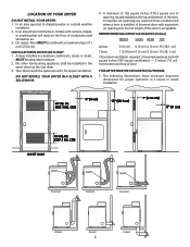
... under counter model clothes dryers, the top panel may need a plastic knife to scratch the paint. 2. To change the direction of the door opening . NOTE: You may be reversed at any time without additional parts. Place nearby for installation. 2.Return the dryer to an upright position. Hold the door firmly before removing the last two screws. 3. Remove the four hinge hole plugs from each side), carefully lay the dryer on...
... under counter model clothes dryers, the top panel may need a plastic knife to scratch the paint. 2. To change the direction of the door opening . NOTE: You may be reversed at any time without additional parts. Place nearby for installation. 2.Return the dryer to an upright position. Hold the door firmly before removing the last two screws. 3. Remove the four hinge hole plugs from each side), carefully lay the dryer on...
Installation Instructions
Page 6
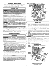
... have longer drying times than operating on the terminal block. For a permanently connected dryer: 1. Thread a U.L. Reinstall the terminal block cover. This appliance MUST be plugged directly into an appropriate, copper wired receptacle that the strain relief does not turn. 9. or an equipment grounding conductor must be purchased, allowing some slack in this manual for the proper power cord to be installed onto power cord. Remove the screws securing the terminal block access cover and the...
... have longer drying times than operating on the terminal block. For a permanently connected dryer: 1. Thread a U.L. Reinstall the terminal block cover. This appliance MUST be plugged directly into an appropriate, copper wired receptacle that the strain relief does not turn. 9. or an equipment grounding conductor must be purchased, allowing some slack in this manual for the proper power cord to be installed onto power cord. Remove the screws securing the terminal block access cover and the...
Installation Instructions
Page 7
... (neutral) power cord conductor from the power cord and the neutral ground wire from the dryer harness (removed from the green ground screw located above the terminal block. 4. Tighten the screw securely. 7. Reinstall the terminal block access cover. Connect the exhaust duct to 0.96 cm) reducer for the gas line to be bled of air. THE DRYER MUST BE LEVEL AND RESTING SOLID ON ALL FOUR LEGS. 4. Plug the power cord into the outlet. 5. Also...
... (neutral) power cord conductor from the power cord and the neutral ground wire from the dryer harness (removed from the green ground screw located above the terminal block. 4. Tighten the screw securely. 7. Reinstall the terminal block access cover. Connect the exhaust duct to 0.96 cm) reducer for the gas line to be bled of air. THE DRYER MUST BE LEVEL AND RESTING SOLID ON ALL FOUR LEGS. 4. Plug the power cord into the outlet. 5. Also...
Installation Instructions
Page 8
... that are subject to replace appliance light bulbs, air filters, water filters, other consumables, or knobs, handles, or other than in accordance with original serial numbers that has been transferred from its original owner to any obligations under this warranty. DISCLAIMER OF IMPLIED WARRANTIES; THIS WRITTEN WARRANTY GIVES YOU SPECIFIC LEGAL RIGHTS. Product features or specifications as set forth below . Products with the provided instructions. 11. Products purchased...
... that are subject to replace appliance light bulbs, air filters, water filters, other consumables, or knobs, handles, or other than in accordance with original serial numbers that has been transferred from its original owner to any obligations under this warranty. DISCLAIMER OF IMPLIED WARRANTIES; THIS WRITTEN WARRANTY GIVES YOU SPECIFIC LEGAL RIGHTS. Product features or specifications as set forth below . Products with the provided instructions. 11. Products purchased...
Wiring Schematic
Page 1
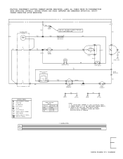
... IN MODELS PROVIDED ACCUMULATOR WITH 4-WIRE POWER CORD. CONNECT DRYER TO A 30 AMP INDIVIDUAL BRANCH CIRCUIT. 3. GRN CABINET BASE YEL HEATER 4500 WATTS BLK DRIVE MOTOR HEATER 1 ACCUMULATION WIRING DIAGRAM P/N 134308200 BLK RED BLUE BLUE NO GRAY DOOR SWITCH A RED WHT YoM MT" THERMAL LIMITER FABRIC SELECTOR SWITCH WH TAN INDICATOR LIGHT YEL START RUN MOTOR TAN V GRAY START SWITCH ORS WIRING CODES (:8;) QUICK DISCONNECT TERMINAL CONNECTION ± NO CONNECTION MOTOR SWITCH -IMF- ALL WIRING MUST CONFORM TO LOCAL ELECTRICAL CODES. 2. SHOWN...
... IN MODELS PROVIDED ACCUMULATOR WITH 4-WIRE POWER CORD. CONNECT DRYER TO A 30 AMP INDIVIDUAL BRANCH CIRCUIT. 3. GRN CABINET BASE YEL HEATER 4500 WATTS BLK DRIVE MOTOR HEATER 1 ACCUMULATION WIRING DIAGRAM P/N 134308200 BLK RED BLUE BLUE NO GRAY DOOR SWITCH A RED WHT YoM MT" THERMAL LIMITER FABRIC SELECTOR SWITCH WH TAN INDICATOR LIGHT YEL START RUN MOTOR TAN V GRAY START SWITCH ORS WIRING CODES (:8;) QUICK DISCONNECT TERMINAL CONNECTION ± NO CONNECTION MOTOR SWITCH -IMF- ALL WIRING MUST CONFORM TO LOCAL ELECTRICAL CODES. 2. SHOWN...
Wiring Schematic
Page 2
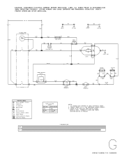
... THERMOSTAT SENSOR IGNITER 4 ORG WHT WHT WHT WHT ORG ORG SECONDARY COIL BOOSTER COIL HOLDING COIL WIRING CODES ® QUICK DISCONNECT TERMINAL CONNECTION + 4.. -Imp_,,n_ NO CONNECTION MOTOR SWITCH SPLICE MOTOR PROTECTOR fh CHASSIS (CABINET) GROUND (D SCREW TERMINAL HARNESS CONNECTOR TERMINAL RE INSULATED TERMINAL DRIVE WQM HEATER FABRIC SELECTOR SWITCH FUNCTION RESISTANCE 0 HIGH MEDIUM LOW 00 2.4K ±5% 10 MAX NOTES: 1. !CAUTION: DISCONNECT ELECTRIC CURRENT BEFORE SERVICING. CONNECT DRYER...
... THERMOSTAT SENSOR IGNITER 4 ORG WHT WHT WHT WHT ORG ORG SECONDARY COIL BOOSTER COIL HOLDING COIL WIRING CODES ® QUICK DISCONNECT TERMINAL CONNECTION + 4.. -Imp_,,n_ NO CONNECTION MOTOR SWITCH SPLICE MOTOR PROTECTOR fh CHASSIS (CABINET) GROUND (D SCREW TERMINAL HARNESS CONNECTOR TERMINAL RE INSULATED TERMINAL DRIVE WQM HEATER FABRIC SELECTOR SWITCH FUNCTION RESISTANCE 0 HIGH MEDIUM LOW 00 2.4K ±5% 10 MAX NOTES: 1. !CAUTION: DISCONNECT ELECTRIC CURRENT BEFORE SERVICING. CONNECT DRYER...


