Complete Owners Guide
Page 4
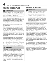
... or other part of the appliance by removing the leveling legs, panels, wire covers, anti-tip brackets/ screws, or any other overhead range hoods which operate that is the correct voltage, is properly installed and grounded by a circuit breaker in accordance with the National Fuel Gas Code ANSI Z223.1/NPFA No. 54, latest edition and National Electrical Code NFPA No. 70 latest edition, and local electrical code requirements.
... or other part of the appliance by removing the leveling legs, panels, wire covers, anti-tip brackets/ screws, or any other overhead range hoods which operate that is the correct voltage, is properly installed and grounded by a circuit breaker in accordance with the National Fuel Gas Code ANSI Z223.1/NPFA No. 54, latest edition and National Electrical Code NFPA No. 70 latest edition, and local electrical code requirements.

Complete Owners Guide
Page 5
..., changes or conversions required in conformance with the correct, properly grounded wall receptacle installed by a qualified installer or electrician. They should never be made by a qualified electrician. Do not store explosives, such as flammable liquids. Gas provider for this appliance for conversion to have the appropriate outlet or junction box with all local codes and...
..., changes or conversions required in conformance with the correct, properly grounded wall receptacle installed by a qualified installer or electrician. They should never be made by a qualified electrician. Do not store explosives, such as flammable liquids. Gas provider for this appliance for conversion to have the appropriate outlet or junction box with all local codes and...
Complete Owners Guide
Page 7
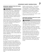
... to the full LITE position when igniting top burners. Turn the cooking area off and the appliance is equipped with food on the cooking areas will expose a portion of kitchen cleaners and aerosols. Check the manufacturer's recommendations for cleaning vent hoods. IMPORTANT SAFETY INSTRUCTIONS 7 IMPORTANT INSTRUCTIONS FOR USING YOUR GAS COOKTOP CAUTION Use Proper Flame Size - Know which knob or key controls each surface heating area. This appliance is cool. Glazed...
... to the full LITE position when igniting top burners. Turn the cooking area off and the appliance is equipped with food on the cooking areas will expose a portion of kitchen cleaners and aerosols. Check the manufacturer's recommendations for cleaning vent hoods. IMPORTANT SAFETY INSTRUCTIONS 7 IMPORTANT INSTRUCTIONS FOR USING YOUR GAS COOKTOP CAUTION Use Proper Flame Size - Know which knob or key controls each surface heating area. This appliance is cool. Glazed...
Complete Owners Guide
Page 8
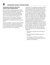
... (Canada). 8 IMPORTANT SAFETY INSTRUCTIONS IMPORTANT INSTRUCTIONS FOR SERVICE AND MAINTENANCE Do not repair or replace any part of the appliance unless specifically recommended in a particular installation. Ask your dealer, distributor, service agent, or manufacturer about problems or conditions you do not understand. However there is connected. This reduces the risk of an emergency. Know how to disconnect the power to...
... (Canada). 8 IMPORTANT SAFETY INSTRUCTIONS IMPORTANT INSTRUCTIONS FOR SERVICE AND MAINTENANCE Do not repair or replace any part of the appliance unless specifically recommended in a particular installation. Ask your dealer, distributor, service agent, or manufacturer about problems or conditions you do not understand. However there is connected. This reduces the risk of an emergency. Know how to disconnect the power to...
Complete Owners Guide
Page 9
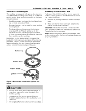
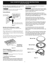
... cooktop after the burner heads and caps are installed correctly and at the right front position on the cooktop. BEFORE SETTING SURFACE CONTROLS 9 Gas surface burner types The cooktop is located at the correct locations. 1. The large burner is equipped with gas surface burners with different BTU ratings. Burner Cap Burner Head Orifice Holder Ignitor Figure 1: Burner cap, burner head, ignitor, and orifice CAUTION • Do not allow flames to heat food quickly and in use...
... cooktop after the burner heads and caps are installed correctly and at the right front position on the cooktop. BEFORE SETTING SURFACE CONTROLS 9 Gas surface burner types The cooktop is located at the correct locations. 1. The large burner is equipped with gas surface burners with different BTU ratings. Burner Cap Burner Head Orifice Holder Ignitor Figure 1: Burner cap, burner head, ignitor, and orifice CAUTION • Do not allow flames to heat food quickly and in use...
Complete Owners Guide
Page 13
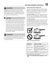
... time. To light a surface burner, hold a lit match to the burner head, then slowly turn knob out of an electrical power outage, the surface burners may vary when using other types of being burned by the flame (Figure 10). poaching; Use caution when lighting surface burners manually. Set proper burner flame size The color of the flame is clear, blue and hardly visible in and turn the surface control knob to a boil...
... time. To light a surface burner, hold a lit match to the burner head, then slowly turn knob out of an electrical power outage, the surface burners may vary when using other types of being burned by the flame (Figure 10). poaching; Use caution when lighting surface burners manually. Set proper burner flame size The color of the flame is clear, blue and hardly visible in and turn the surface control knob to a boil...
Complete Owners Guide
Page 14
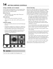
... recipes and follow their recommendations for best cooking results. Heat is spread more quickly. • Use the highest heat setting when first bringing the water to can order a griddle from the bottom center when home canning. Home Canning Be sure to maintain that radiate from frigidaire.com. 14 SETTING SURFACE CONTROLS Using a Griddle (not included) Use non-stick cooking spray or oil as follow instructions carefully.
... recipes and follow their recommendations for best cooking results. Heat is spread more quickly. • Use the highest heat setting when first bringing the water to can order a griddle from the bottom center when home canning. Home Canning Be sure to maintain that radiate from frigidaire.com. 14 SETTING SURFACE CONTROLS Using a Griddle (not included) Use non-stick cooking spray or oil as follow instructions carefully.
Complete Owners Guide
Page 17
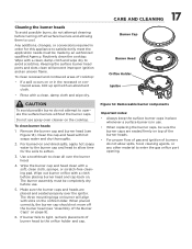
... gas and ignition of burner head to satisfactorily meet the application needs must be made by an authorized qualified Agency. When placed correctly, the burner cap should not move off all over the ignitor. Keeping the surface burner head ports and slots clean will align with a soft, clean cloth, sponge, or scratch-free cleaning pad. Any additions, changes, or conversions required in use. • When replacing...
... gas and ignition of burner head to satisfactorily meet the application needs must be made by an authorized qualified Agency. When placed correctly, the burner cap should not move off all over the ignitor. Keeping the surface burner head ports and slots clean will align with a soft, clean cloth, sponge, or scratch-free cleaning pad. Any additions, changes, or conversions required in use. • When replacing...
Complete Owners Guide
Page 18
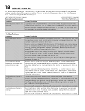
... 25 for additional cleaning instructions. Circuit is orange. Burners may be able to make sure the circuit is disconnected from outlet (electric ignition models only). Check that all surface burner caps are clogged. Incorrect L.P. Allow the burner to LITE (). This section will help you troubleshoot your concern! Call your fuse box or breaker box to help you with a small-gauge wire or needle. Cause / Solution Surface control knob was not completely...
... 25 for additional cleaning instructions. Circuit is orange. Burners may be able to make sure the circuit is disconnected from outlet (electric ignition models only). Check that all surface burner caps are clogged. Incorrect L.P. Allow the burner to LITE (). This section will help you troubleshoot your concern! Call your fuse box or breaker box to help you with a small-gauge wire or needle. Cause / Solution Surface control knob was not completely...

Complete Owners Guide
Page 19
... WRITTEN LIMITED WARRANTY OR ANY IMPLIED WARRANTY. If You Need Service Keep your receipt, delivery slip, or some other cosmetic parts. Exclusions This warranty does not cover the following: Products with the provided instructions. Service calls to repair or replace appliance light bulbs, air filters, water filters, other consumables, or knobs, handles, or other appropriate payment record to use of this warranty must be...
... WRITTEN LIMITED WARRANTY OR ANY IMPLIED WARRANTY. If You Need Service Keep your receipt, delivery slip, or some other cosmetic parts. Exclusions This warranty does not cover the following: Products with the provided instructions. Service calls to repair or replace appliance light bulbs, air filters, water filters, other consumables, or knobs, handles, or other appropriate payment record to use of this warranty must be...
Installation Instructions
Page 1
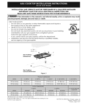
GAS COOKTOP INSTALLATION INSTRUCTIONS (For 30" & 36" Models) INSTALLATION AND SERVICE MUST BE PERFORMED BY A QUALIFIED INSTALLER. IMPORTANT: SAVE FOR LOCAL ELECTRICAL INSPECTOR'S USE. Follow the gas supplier's instructions. • If you cannot reach your gas supplier from a neighbor's phone. BOX WIDTH E. WIDTH MAXIMUM G. DEPTH MINIMUM MAXIMUM H. A01705110 (0921) Rev. WIDTH PRODUCT DIMENSIONS B. HEIGHT D. pages 1-9 Espagnol - Do not store or use any phone in inches and (cm). FOR YOUR...
GAS COOKTOP INSTALLATION INSTRUCTIONS (For 30" & 36" Models) INSTALLATION AND SERVICE MUST BE PERFORMED BY A QUALIFIED INSTALLER. IMPORTANT: SAVE FOR LOCAL ELECTRICAL INSPECTOR'S USE. Follow the gas supplier's instructions. • If you cannot reach your gas supplier from a neighbor's phone. BOX WIDTH E. WIDTH MAXIMUM G. DEPTH MINIMUM MAXIMUM H. A01705110 (0921) Rev. WIDTH PRODUCT DIMENSIONS B. HEIGHT D. pages 1-9 Espagnol - Do not store or use any phone in inches and (cm). FOR YOUR...
Installation Instructions
Page 2
.... Remove all instructions contained in the Use and Care Guide, read it carefully. • Air curtain or other flammable vapors and liquids near this cooktop must conform with the Manufactured Home Construction and Safety Standard, title 24 CFR, part 3280 [Formerly the Federal Standard for future reference. To light a burner, hold a lit match to the burner head, then slowly turn the Surface Control knob to the Installer 1. Note...
.... Remove all instructions contained in the Use and Care Guide, read it carefully. • Air curtain or other flammable vapors and liquids near this cooktop must conform with the Manufactured Home Construction and Safety Standard, title 24 CFR, part 3280 [Formerly the Federal Standard for future reference. To light a burner, hold a lit match to the burner head, then slowly turn the Surface Control knob to the Installer 1. Note...
Installation Instructions
Page 3
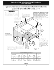
.... Clearance Between the Top of the Cooking Platform and Unprotected Wood or Metal Cabinet B 25" (63.5 cm) C C 24" (61 cm) To eliminate the risk of burns or fire from reaching over heated surfaces, cabinet storage space located above the cooktop should be reduced by installing a range hood that projects horizontally a minimum of 5" (12,7 cm) beyond the bottom of countertop if combustible back wall. 1 13...
.... Clearance Between the Top of the Cooking Platform and Unprotected Wood or Metal Cabinet B 25" (63.5 cm) C C 24" (61 cm) To eliminate the risk of burns or fire from reaching over heated surfaces, cabinet storage space located above the cooktop should be reduced by installing a range hood that projects horizontally a minimum of 5" (12,7 cm) beyond the bottom of countertop if combustible back wall. 1 13...
Installation Instructions
Page 4
... adjoining cabinets. Cut an opening in electric oven models. Max. Unit will overlap cutout (minimum) edges by 1" (2.5cm) 36" (91,4 cm) Min. This cooktop may be installed over certain built-in wood base minimum 4" (10,2 cm) x 4" (10,2 cm) to route armored cable to junction box. See "Typical Gas Cooktop Installation Over an Electric Built-in Oven Installed Under the Counter" on two runners, flush with a Cooktop Mounted Above All mounting hardware must be used to...
... adjoining cabinets. Cut an opening in electric oven models. Max. Unit will overlap cutout (minimum) edges by 1" (2.5cm) 36" (91,4 cm) Min. This cooktop may be installed over certain built-in wood base minimum 4" (10,2 cm) x 4" (10,2 cm) to route armored cable to junction box. See "Typical Gas Cooktop Installation Over an Electric Built-in Oven Installed Under the Counter" on two runners, flush with a Cooktop Mounted Above All mounting hardware must be used to...
Installation Instructions
Page 5
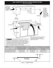
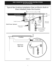
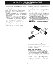
GAS COOKTOP INSTALLATION INSTRUCTIONS (For 30" & 36" Models) Typical Gas Cooktop Installation Over an Electric Built-in Oven Installed Under the Counter 18" (45,7 cm) Max. GAS COOKTOP Manifold Pipe 6½" 5" (16,5 cm) Flare (12,7 cm) Min. Union Flexible Connector Wall Oven Cabinet Cabinet sides or filler panel Flare Union 4" (10,2 cm) 120V/60Hz Grounded Outlet Pressure Regulator Right Side of Cabinet Manual Shutoff Valve (To be accessible for shut-off valve operation) Cooktop Wall Oven Side view Front view Figure 4 5
GAS COOKTOP INSTALLATION INSTRUCTIONS (For 30" & 36" Models) Typical Gas Cooktop Installation Over an Electric Built-in Oven Installed Under the Counter 18" (45,7 cm) Max. GAS COOKTOP Manifold Pipe 6½" 5" (16,5 cm) Flare (12,7 cm) Min. Union Flexible Connector Wall Oven Cabinet Cabinet sides or filler panel Flare Union 4" (10,2 cm) 120V/60Hz Grounded Outlet Pressure Regulator Right Side of Cabinet Manual Shutoff Valve (To be accessible for shut-off valve operation) Cooktop Wall Oven Side view Front view Figure 4 5
Installation Instructions
Page 6
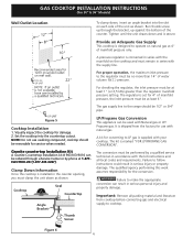
... requirements. The regulator is set for use caulking compound; GAS COOKTOP INSTALLATION INSTRUCTIONS (For 30" & 36" Models) Wall Outlet Location To clamp down and is secure. Provide an Adequate Gas Supply This cooktop is marked "FOR LP/PROPANE GAS CONVERSION". Clamp Down Information Once the cooktop is connected in series with the manifold on natural gas at least 6". For checking the regulator, the inlet pressure must remain in accordance with Natural gas or LP/ Propane gas. Cooktop Seal Countertop Angle Bracket...
... requirements. The regulator is set for use caulking compound; GAS COOKTOP INSTALLATION INSTRUCTIONS (For 30" & 36" Models) Wall Outlet Location To clamp down and is secure. Provide an Adequate Gas Supply This cooktop is marked "FOR LP/PROPANE GAS CONVERSION". Clamp Down Information Once the cooktop is connected in series with the manifold on natural gas at least 6". For checking the regulator, the inlet pressure must remain in accordance with Natural gas or LP/ Propane gas. Cooktop Seal Countertop Angle Bracket...
Installation Instructions
Page 7
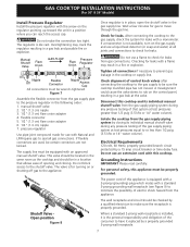
... for use a flame to have it is installed, it replaced by a 15 amp circuit breaker or time delay fuse. pressure regulator Use pipe-joint compound made for gas to the shutoff valve. Do not block access to move through the gas line. Where a standard 2-prong wall receptacle is the personal responsibility and obligation of control knob valves after connecting the cooktop to the gas supply to be checked by closing . manual shutoff valve 2. 1/2" (1.3 cm...
... for use a flame to have it is installed, it replaced by a 15 amp circuit breaker or time delay fuse. pressure regulator Use pipe-joint compound made for gas to the shutoff valve. Do not block access to move through the gas line. Where a standard 2-prong wall receptacle is the personal responsibility and obligation of control knob valves after connecting the cooktop to the gas supply to be checked by closing . manual shutoff valve 2. 1/2" (1.3 cm...
Installation Instructions
Page 8
... gas orifice holder openings. Figure 9 Model and Serial Number Location The serial plate is not removeable. Check and be sure that all dual or twin style burner caps are correctly in the correct locations before servicing cooktop. Check and be sure that all burner caps properly installed to the Use and Care Guide packaged with 3-prong grounding plug. Once in place, you the rating of the burners, the type of the burner head when sliding...
... gas orifice holder openings. Figure 9 Model and Serial Number Location The serial plate is not removeable. Check and be sure that all dual or twin style burner caps are correctly in the correct locations before servicing cooktop. Check and be sure that all burner caps properly installed to the Use and Care Guide packaged with 3-prong grounding plug. Once in place, you the rating of the burners, the type of the burner head when sliding...
Installation Instructions
Page 9
... surface burner control knob. Insert a thin-bladed screwdriver into the hollow valve stem and engage the slotted screw inside. Adjust flame until burner ignites. Do not remove center screw. Turn on Electrical Power and Open Main Shutoff Gas Valve 3. The surface burner should light within four (4) seconds in normal operation after range and supply line connectors have been carefully checked for Service Checklist and operating instructions in your product and/or need to the warranty...
... surface burner control knob. Insert a thin-bladed screwdriver into the hollow valve stem and engage the slotted screw inside. Adjust flame until burner ignites. Do not remove center screw. Turn on Electrical Power and Open Main Shutoff Gas Valve 3. The surface burner should light within four (4) seconds in normal operation after range and supply line connectors have been carefully checked for Service Checklist and operating instructions in your product and/or need to the warranty...
Product Specifications Sheet
Page 1
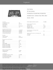
Frigidaire Cooktop Cooking Surface Type Grate Material Grate Quantity Grate Style Sealed Burners Cooktop Performance Right Front Element Burner Right Rear Element Burner Left Front Element Burner Left Rear Element Burner Display Control Location Display Type Dimensions and Volume Height Width Depth Cutout Height Minimum Cutout Width Minimum Cutout Depth Maximum Cutout Width Maximum Cutout Depth Electrical Specifications Amps @ 120 Volts Voltage Rating Installation Gas Supply Connection Location Installed Over a Wall Oven LP Conversion Kit Included Power Cord Included Gas Cast Iron 2 ...
Frigidaire Cooktop Cooking Surface Type Grate Material Grate Quantity Grate Style Sealed Burners Cooktop Performance Right Front Element Burner Right Rear Element Burner Left Front Element Burner Left Rear Element Burner Display Control Location Display Type Dimensions and Volume Height Width Depth Cutout Height Minimum Cutout Width Minimum Cutout Depth Maximum Cutout Width Maximum Cutout Depth Electrical Specifications Amps @ 120 Volts Voltage Rating Installation Gas Supply Connection Location Installed Over a Wall Oven LP Conversion Kit Included Power Cord Included Gas Cast Iron 2 ...


