

Installation Instructions (All Languages)
Page 1
All about the Installation of your Dryer TABLE OF CONTENTS Important Safety Instructions 2-3 Reversing Door 18-21 Installation Requirements 4-10 Accessories 22 Installed Dryer Dimensions 11 Français 23 Installation Instructions 12-17 Español 45 137336500A (1003)
All about the Installation of your Dryer TABLE OF CONTENTS Important Safety Instructions 2-3 Reversing Door 18-21 Installation Requirements 4-10 Accessories 22 Installed Dryer Dimensions 11 Français 23 Installation Instructions 12-17 Español 45 137336500A (1003)
Installation Instructions (All Languages)
Page 2
... from a neighbor's phone. Children might use gasoline or other flammable vapors and liquids in this or any appliance. Do not stack dryer on top of another dryer. WHAT TO DO IF YOU SMELL GAS: • Do not try to collapse, be applied when installing, operating and maintaining any other... of the National Electrical Code, ANSI/NFPA 70, or in Canada, the Canadian electrical code C22.1 part 1. • The gas service to the dryer must be followed to minimize the risk of fire or explosion or to cover every possible condition and situation that may occur. IMPORTANT SAFETY...
... from a neighbor's phone. Children might use gasoline or other flammable vapors and liquids in this or any appliance. Do not stack dryer on top of another dryer. WHAT TO DO IF YOU SMELL GAS: • Do not try to collapse, be applied when installing, operating and maintaining any other... of the National Electrical Code, ANSI/NFPA 70, or in Canada, the Canadian electrical code C22.1 part 1. • The gas service to the dryer must be followed to minimize the risk of fire or explosion or to cover every possible condition and situation that may occur. IMPORTANT SAFETY...
Installation Instructions (All Languages)
Page 3
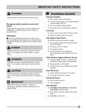
...DANGER DANGER indicates an imminently hazardous situation which is the safety alert symbol. It is setting solid on all corners Gas Supply (Gas Dryer) ‰ Manual shutoff valve present in supply ‰ All connections sealed with a WARNING or CAUTION based on ‰ No ...manual are labeled with approved sealer and wrench tight ‰ Conversion kit for function Electrical Power ‰ House power turned on ‰ Dryer plugged in Final Checks ‰ Installation Instructions and Use and Care Guide read all connections - WARNING WARNING indicates a potentially hazardous situation ...
...DANGER DANGER indicates an imminently hazardous situation which is the safety alert symbol. It is setting solid on all corners Gas Supply (Gas Dryer) ‰ Manual shutoff valve present in supply ‰ All connections sealed with a WARNING or CAUTION based on ‰ No ...manual are labeled with approved sealer and wrench tight ‰ Conversion kit for function Electrical Power ‰ House power turned on ‰ Dryer plugged in Final Checks ‰ Installation Instructions and Use and Care Guide read all connections - WARNING WARNING indicates a potentially hazardous situation ...

Installation Instructions (All Languages)
Page 4
...wire cord connection instructions see ELECTRICAL CONNECTIONS FOR A 3-WIRE SYSTEM. 4-WIRE POWER SUPPLY CORD KIT (not supplied) 4-wire receptacle (NEMA type 14-30R) The dryer MUST employ a 4-conductor power supply cord NEMA 14-30 type SRDT or ST (as required) rated at 240 volt AC minimum, 30 amp, with 3 ... the neutral link is not recommended. NEMA 10-30R or NEMA 14-30R receptacle to neutral unless it was manufactured for use of this dryer with 30 amp. time delay fuses or circuit breakers. branch circuit fused with power created by gas powered generators, solar powered generators, wind...
...wire cord connection instructions see ELECTRICAL CONNECTIONS FOR A 3-WIRE SYSTEM. 4-WIRE POWER SUPPLY CORD KIT (not supplied) 4-wire receptacle (NEMA type 14-30R) The dryer MUST employ a 4-conductor power supply cord NEMA 14-30 type SRDT or ST (as required) rated at 240 volt AC minimum, 30 amp, with 3 ... the neutral link is not recommended. NEMA 10-30R or NEMA 14-30R receptacle to neutral unless it was manufactured for use of this dryer with 30 amp. time delay fuses or circuit breakers. branch circuit fused with power created by gas powered generators, solar powered generators, wind...

Installation Instructions (All Languages)
Page 5
... gas leaks. plugged tapping, accessible for test gauge connection, MUST be installed immediately upstream of the gas supply connection to the dryer. 6 The dryer MUST be disconnected from the gas supply piping system during any circumstances, cut, remove, or bypass the grounding prong. branch circuit...supply piping system at test pressures in excess of 1/2 psig (3.45 kPa). 7 The dryer MUST be used to connect your dryer to or less than 1/2 psig (3.45 kPa). 8 Connections for gas dryer CIRCUIT - INSTALLATION REQUIREMENTS Electrical requirements for the gas supply must comply with 15 amp....
... gas leaks. plugged tapping, accessible for test gauge connection, MUST be installed immediately upstream of the gas supply connection to the dryer. 6 The dryer MUST be disconnected from the gas supply piping system during any circumstances, cut, remove, or bypass the grounding prong. branch circuit...supply piping system at test pressures in excess of 1/2 psig (3.45 kPa). 7 The dryer MUST be used to connect your dryer to or less than 1/2 psig (3.45 kPa). 8 Connections for gas dryer CIRCUIT - INSTALLATION REQUIREMENTS Electrical requirements for the gas supply must comply with 15 amp....
Installation Instructions (All Languages)
Page 6
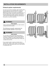
... and safe operation of your present system is in operation. The following are known to installing dryer duct. WARNING FIRE HAZARD Do not install a clothes dryer with a rigid or semi-rigid metal duct. If your dryer. WARNING FIRE HAZARD Failure to prevent drafts and the entrance of fire. When the... 4 inch (102 mm) diameter rigid or flexible metal duct and approved vent hood which has a swing-out damper(s) that open when the dryer is made up of 12 inches (30.5 cm) clearance between the vent hood and the ground or any lint prior to collapse, be easily crushed...
... and safe operation of your present system is in operation. The following are known to installing dryer duct. WARNING FIRE HAZARD Do not install a clothes dryer with a rigid or semi-rigid metal duct. If your dryer. WARNING FIRE HAZARD Failure to prevent drafts and the entrance of fire. When the... 4 inch (102 mm) diameter rigid or flexible metal duct and approved vent hood which has a swing-out damper(s) that open when the dryer is made up of 12 inches (30.5 cm) clearance between the vent hood and the ground or any lint prior to collapse, be easily crushed...

Installation Instructions (All Languages)
Page 7
...Use an approved vent hood to assemble the exhaust system. Regularly inspect the outdoor exhaust opening and in contact with metal foil duct tape. The dryer MUST NOT be installed downstream with the flow of lint in a fire hazard. • Do not screen the exhaust ends of... the vent system, or use any concealed space of a building. Do not exhaust dryer into a chimney, a wall, a ceiling, an attic, a crawl space or any accumulation of lint around the outdoor exhaust opening and remove any concealed space...
...Use an approved vent hood to assemble the exhaust system. Regularly inspect the outdoor exhaust opening and in contact with metal foil duct tape. The dryer MUST NOT be installed downstream with the flow of lint in a fire hazard. • Do not screen the exhaust ends of... the vent system, or use any concealed space of a building. Do not exhaust dryer into a chimney, a wall, a ceiling, an attic, a crawl space or any accumulation of lint around the outdoor exhaust opening and remove any concealed space...
Installation Instructions (All Languages)
Page 8
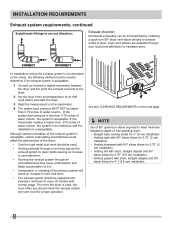
If the manometer reading is higher than .075 inches of water column, the system is too restrictive and the installation is acceptable. Dryer vent elbows are available through a roof may cause condensation and faster accumulation of lint. • Compression or crimping of the exhaust system will ... also CLEARANCE REQUIREMENTS on the next page. Í NOTE Use of 90° quick-turn 90° dryer vent elbow directly to down ) and start the dryer. 3 Read the measurement on the manometer. 4 The system back pressure MUST NOT be used to determine if the exhaust system is used . •...
If the manometer reading is higher than .075 inches of water column, the system is too restrictive and the installation is acceptable. Dryer vent elbows are available through a roof may cause condensation and faster accumulation of lint. • Compression or crimping of the exhaust system will ... also CLEARANCE REQUIREMENTS on the next page. Í NOTE Use of 90° quick-turn 90° dryer vent elbow directly to down ) and start the dryer. 3 Read the measurement on the manometer. 4 The system back pressure MUST NOT be used to determine if the exhaust system is used . •...

Installation Instructions (All Languages)
Page 9
... in a garage, it will come in diameter with a maximum slope of combustion and ventilation air. 3 On carpet. IMPORTANT DO NOT INSTALL YOUR DRYER: 1 In an area exposed to dripping water or outside weather conditions. 2 In an area where it must be solid with no obstructions. This ... & Safety Standard, Title 24 CFR, Part 32-80 (formerly the Federal Standard for outside make up air. Floor MUST be a minimum of the dryer exhaust outlet. 6 Installer MUST anchor this guide for other flammables are kept or stored. Failure to be exhausted outside (outdoors, not beneath the...
... in a garage, it will come in diameter with a maximum slope of combustion and ventilation air. 3 On carpet. IMPORTANT DO NOT INSTALL YOUR DRYER: 1 In an area exposed to dripping water or outside weather conditions. 2 In an area where it must be solid with no obstructions. This ... & Safety Standard, Title 24 CFR, Part 32-80 (formerly the Federal Standard for outside make up air. Floor MUST be a minimum of the dryer exhaust outlet. 6 Installer MUST anchor this guide for other flammables are kept or stored. Failure to be exhausted outside (outdoors, not beneath the...

Installation Instructions (All Languages)
Page 10
... (0 cm) n/a UnderCounter 0" (0 cm) 0" (0 cm)* 0" (0 cm) n/a Closet 0" (0 cm) 0" (0 cm)* 0" (0 cm) 1" (2.54 cm) * Dryer must be installed in the same closet as the gas dryer. 3 Your dryer needs the space around it for the full length of the door, is acceptable. A louvered door with a solid door. 4 Closet...the top and bottom of the door is required. INSTALLATION REQUIREMENTS Clearance requirements, continued Installation in a Recess or Closet 1 A dryer installed in a bedroom, bathroom, recess or closet, MUST be exhausted outdoors. 2 No other fuel burning appliance shall be ...
... (0 cm) n/a UnderCounter 0" (0 cm) 0" (0 cm)* 0" (0 cm) n/a Closet 0" (0 cm) 0" (0 cm)* 0" (0 cm) 1" (2.54 cm) * Dryer must be installed in the same closet as the gas dryer. 3 Your dryer needs the space around it for the full length of the door, is acceptable. A louvered door with a solid door. 4 Closet...the top and bottom of the door is required. INSTALLATION REQUIREMENTS Clearance requirements, continued Installation in a Recess or Closet 1 A dryer installed in a bedroom, bathroom, recess or closet, MUST be exhausted outdoors. 2 No other fuel burning appliance shall be ...
Installation Instructions (All Languages)
Page 11
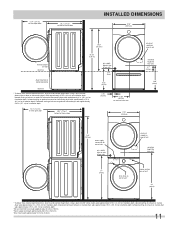
...open door 30.3" (77cm)* to front of closed door INSTALLED DIMENSIONS 27.0" (68.5cm) 36.0" (91.5cm) freestand dryer on floor floor line 51.25" (130cm) dryer mounted on freestanding dryer) adds approximately 0.75 in. (2.0 cm) to installation depth. Using a quick-turn 90° elbow (right) adds... 2.25 in. (5.7 cm) to installation depth. 51.4" (131cm) to clear open door 30.3" (77cm)* to front of exhaust on stacked dryer adds approximately 3.75 in. (9.5 cm) to installation depth. 1Hot and cold inlet hose length approximately 43 inches (109cm) 2Power supply cord length...
...open door 30.3" (77cm)* to front of closed door INSTALLED DIMENSIONS 27.0" (68.5cm) 36.0" (91.5cm) freestand dryer on floor floor line 51.25" (130cm) dryer mounted on freestanding dryer) adds approximately 0.75 in. (2.0 cm) to installation depth. Using a quick-turn 90° elbow (right) adds... 2.25 in. (5.7 cm) to installation depth. 51.4" (131cm) to clear open door 30.3" (77cm)* to front of exhaust on stacked dryer adds approximately 3.75 in. (9.5 cm) to installation depth. 1Hot and cold inlet hose length approximately 43 inches (109cm) 2Power supply cord length...

Installation Instructions (All Languages)
Page 12
... shock. • Do not use an extension cord with the circuit conductors and connected to the equipmentgrounding terminal or lead on this dryer. or an equipment grounding conductor must be properly grounded. INSTALLATION INSTRUCTIONS Electrical installation The following are specific requirements for proper and safe... plug MUST be plugged into an appropriate, copper wired receptacle that is not attached, the cord can be pulled out of the dryer and can result in this manual for the proper power cord to withstand the amounts of electrical shock. If the strain relief is...
... shock. • Do not use an extension cord with the circuit conductors and connected to the equipmentgrounding terminal or lead on this dryer. or an equipment grounding conductor must be properly grounded. INSTALLATION INSTRUCTIONS Electrical installation The following are specific requirements for proper and safe... plug MUST be plugged into an appropriate, copper wired receptacle that is not attached, the cord can be pulled out of the dryer and can result in this manual for the proper power cord to withstand the amounts of electrical shock. If the strain relief is...

Installation Instructions (All Languages)
Page 13
...a proper outlet installed by a qualified electrician. Grounding requirements - Power cord with all local codes and ordinances. Electric dryer (Canada) WARNING ELECTRICAL SHOCK HAZARD Improper connection of the equipment grounding conductor can result in accordance with 3-prong grounded plug 13...type wall receptacle Do not, under any circumstances, cut, remove, or bypass the grounding prong. For a grounded, cord-connected dryer: 1 The dryer MUST be plugged into a properly grounded three-prong receptacle. 2 The plug must be plugged into an appropriate outlet that is...
...a proper outlet installed by a qualified electrician. Grounding requirements - Power cord with all local codes and ordinances. Electric dryer (Canada) WARNING ELECTRICAL SHOCK HAZARD Improper connection of the equipment grounding conductor can result in accordance with 3-prong grounded plug 13...type wall receptacle Do not, under any circumstances, cut, remove, or bypass the grounding prong. For a grounded, cord-connected dryer: 1 The dryer MUST be plugged into a properly grounded three-prong receptacle. 2 The plug must be plugged into an appropriate outlet that is...
Installation Instructions (All Languages)
Page 14
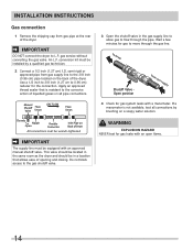
... service without converting the gas valve. semi-rigid or approved pipe from gas supply line to the 3/8 inch (0.96 cm) pipe located on Back of Dryer All connections must be wrench-tightened IMPORTANT The supply line must be in a location that is not available, test all pipe connections. Manual Shutoff Flare... line. If a manometer is resistant to L.P. Do not block access to the gas shutoff valve. 3 Open the shutoff valve in the same room as the dryer and should be located in the gas supply line to allow gas to move through the pipe. Use a 1/2 inch to 3/8 inch (1.27 cm to...
... service without converting the gas valve. semi-rigid or approved pipe from gas supply line to the 3/8 inch (0.96 cm) pipe located on Back of Dryer All connections must be wrench-tightened IMPORTANT The supply line must be in a location that is not available, test all pipe connections. Manual Shutoff Flare... line. If a manometer is resistant to L.P. Do not block access to the gas shutoff valve. 3 Open the shutoff valve in the same room as the dryer and should be located in the gas supply line to allow gas to move through the pipe. Use a 1/2 inch to 3/8 inch (1.27 cm to...

Installation Instructions (All Languages)
Page 15
Tighten both screws securely. Neutral terminal IMPORTANT If moving dryer from the center terminal back to the GREEN screw next to the terminal block. 15 At this time, the strain relief should be loosely in a 3-... death. 1 Turn off power supply to outlet. 2 Remove the screw securing the terminal block access cover in the lower corner on the back of the dryer. 3 Install a UL-approved strain relief according to the power cord/strain relief manufacturer's instructions in a 3-wire system!! Tighten the screw securely. 6 Attach the remaining two...
Tighten both screws securely. Neutral terminal IMPORTANT If moving dryer from the center terminal back to the GREEN screw next to the terminal block. 15 At this time, the strain relief should be loosely in a 3-... death. 1 Turn off power supply to outlet. 2 Remove the screw securing the terminal block access cover in the lower corner on the back of the dryer. 3 Install a UL-approved strain relief according to the power cord/strain relief manufacturer's instructions in a 3-wire system!! Tighten the screw securely. 6 Attach the remaining two...

Installation Instructions (All Languages)
Page 16
... should be retrieved in place. 4 Thread an UNPLUGGED, UL-approved, 30 amp. Tighten both screws securely. Tighten the screw securely. 7 Move the internal dryer harness ground (BLACK) wire to the terminal block and attach it can be loosely in the terminal screw recovery slot below the access panel. Neutral... wire BLACK or RED power wire 16 power cord, NEMA 14-30 type ST or SRDT, through the strain relief. 5 Disconnect the internal (BLACK) dryer harness ground wire from the (GREEN) ground screw next to the terminal block. 6 Attach the ground (GREEN) power cord wire to the cabinet with...
... should be retrieved in place. 4 Thread an UNPLUGGED, UL-approved, 30 amp. Tighten both screws securely. Tighten the screw securely. 7 Move the internal dryer harness ground (BLACK) wire to the terminal block and attach it can be loosely in the terminal screw recovery slot below the access panel. Neutral... wire BLACK or RED power wire 16 power cord, NEMA 14-30 type ST or SRDT, through the strain relief. 5 Disconnect the internal (BLACK) dryer harness ground wire from the (GREEN) ground screw next to the terminal block. 6 Attach the ground (GREEN) power cord wire to the cabinet with...

Installation Instructions (All Languages)
Page 17
... that will save you time and money. 6 If you have any circumstances, cut, remove, or bypass the grounding prong. Power cord with the dryer. Grounding type wall receptacle Do not, under any questions during initial operation, please review the "Avoid Service Checklist" in your Use & Care Guide... 1 Connect the exhaust duct to check A for future reference. Í NOTE A wiring diagram and technical data sheet are located inside the dryer console. Place a level on the power at a circuit breaker/fuse box before calling for service. 7 Place these instructions in a location near the...
... that will save you time and money. 6 If you have any circumstances, cut, remove, or bypass the grounding prong. Power cord with the dryer. Grounding type wall receptacle Do not, under any questions during initial operation, please review the "Avoid Service Checklist" in your Use & Care Guide... 1 Connect the exhaust duct to check A for future reference. Í NOTE A wiring diagram and technical data sheet are located inside the dryer console. Place a level on the power at a circuit breaker/fuse box before calling for service. 7 Place these instructions in a location near the...
Installation Instructions (All Languages)
Page 18
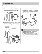
... the small, circular recesses (at 11, 1, 4, 6, and 8 o'clock positions) of the inner door. Remove lower screw first, then upper screw. 4 Gently place dryer door face down on flat work surface. 5 Locate the 5 indented head screws (no. 1-5) in place. 6 Locate the 2 pan head screws (no. 6-7) on... and remove the two hinge screws. REVERSING DOOR Removing the door 1 Protect flat , covered work surface, such as top of dryer or floor near dryer, with both hands, squarely lift door and hinge upward approximately 3/8" (10 mm) so "T" post on back of hinge can slide out ...
... the small, circular recesses (at 11, 1, 4, 6, and 8 o'clock positions) of the inner door. Remove lower screw first, then upper screw. 4 Gently place dryer door face down on flat work surface. 5 Locate the 5 indented head screws (no. 1-5) in place. 6 Locate the 2 pan head screws (no. 6-7) on... and remove the two hinge screws. REVERSING DOOR Removing the door 1 Protect flat , covered work surface, such as top of dryer or floor near dryer, with both hands, squarely lift door and hinge upward approximately 3/8" (10 mm) so "T" post on back of hinge can slide out ...

Installation Instructions (All Languages)
Page 20
... vertically. 20 no. 1-5 no. 6-7 2 Rest the opening of the inner door at a 90 degree angle on outer door, lining up indicators - Grip new strike with dryer manuals.
... vertically. 20 no. 1-5 no. 6-7 2 Rest the opening of the inner door at a 90 degree angle on outer door, lining up indicators - Grip new strike with dryer manuals.
Installation Instructions (All Languages)
Page 22
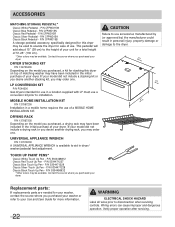
... pedestal will add about 15" (38 cm) to aid in a mobile home requires the use . CAUTION Failure to use a conversion kit prior to the dryer. (682.57.0cm" ) (3185c.0m") (2667.5c"m) DRYING RACK P/N 137067300 Depending on top of matching washer may order one . P/N 5304471229 Classic...available. Replacement parts: If replacements parts are needed for more information. 22 WARNING ELECTRICAL SHOCK HAZARD Label all wires prior to elevate the dryer for use in a location supplied with LP must use accessories manufactured by (or approved by) the manufacturer could result in the initial ...
... pedestal will add about 15" (38 cm) to aid in a mobile home requires the use . CAUTION Failure to use a conversion kit prior to the dryer. (682.57.0cm" ) (3185c.0m") (2667.5c"m) DRYING RACK P/N 137067300 Depending on top of matching washer may order one . P/N 5304471229 Classic...available. Replacement parts: If replacements parts are needed for more information. 22 WARNING ELECTRICAL SHOCK HAZARD Label all wires prior to elevate the dryer for use in a location supplied with LP must use accessories manufactured by (or approved by) the manufacturer could result in the initial ...

