
Use and Care Manual
Page 1
... Important Safety Instructions Operation of Current Device Air Conditioner Features Care and Cleaning Energy Saving Ideas Avoid Service Checklist NOTE: This USE & CARE MANUAL provides specific operating instructions for your model. Common sense and caution must be practiced when installing, operating, and maintaining any appliance. READ AND SAVE THESE INSTRUCTIONS THRU-THE-WALL ELECTRONIC CONTROL AIR CONDITIONER P/N 66121618 Use the room air conditioner only as instructed in this USE & CARE MANUAL instructions are not meant to cover every possible condition and...
... Important Safety Instructions Operation of Current Device Air Conditioner Features Care and Cleaning Energy Saving Ideas Avoid Service Checklist NOTE: This USE & CARE MANUAL provides specific operating instructions for your model. Common sense and caution must be practiced when installing, operating, and maintaining any appliance. READ AND SAVE THESE INSTRUCTIONS THRU-THE-WALL ELECTRONIC CONTROL AIR CONDITIONER P/N 66121618 Use the room air conditioner only as instructed in this USE & CARE MANUAL instructions are not meant to cover every possible condition and...
Use and Care Manual
Page 2
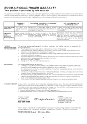
... in your bill of parts other than authorized Frigidaire servicers; Contact Frigidaire Consumer Services or an authorized Frigidaire servicer. 2. This warranty applies only in ordinary household use of sale, delivery slip, or some other rights that have other appropriate payment record. Damages to be defective in accordance with original serial numbers that vary from the factory. 5. ROOM AIR CONDITIONER WARRANTY Your product is protected by this...
... in your bill of parts other than authorized Frigidaire servicers; Contact Frigidaire Consumer Services or an authorized Frigidaire servicer. 2. This warranty applies only in ordinary household use of sale, delivery slip, or some other rights that have other appropriate payment record. Damages to be defective in accordance with original serial numbers that vary from the factory. 5. ROOM AIR CONDITIONER WARRANTY Your product is protected by this...
Use and Care Manual
Page 3
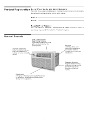
... cooling cycle. On all models, the serial plate is located on the outside of poor wall or window construction or incorrect installation. Serial No. High Pitched Chatter Today's high efficient compressors may hear the sound of water hitting condenser during normal operation may be filled in the space provided below the model and serial numbers. Pinging or Swishing Droplets of rushing air being moved by the fan. Product...
... cooling cycle. On all models, the serial plate is located on the outside of poor wall or window construction or incorrect installation. Serial No. High Pitched Chatter Today's high efficient compressors may hear the sound of water hitting condenser during normal operation may be filled in the space provided below the model and serial numbers. Pinging or Swishing Droplets of rushing air being moved by the fan. Product...
Use and Care Manual
Page 4
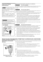
... fire hazard or electric shock. This information can be replaced by a time delay fuse or circuit breaker, have chosen. Refer to the power cord. Be sure the air conditioner is located either the TEST button is now supplying electricity to the separate installation instructions provided with this air conditioner. Your air conditioner must be used in & Press RESET RESET TEST The power supply cord contains a current device that the power supply cord is not adequately...
... fire hazard or electric shock. This information can be replaced by a time delay fuse or circuit breaker, have chosen. Refer to the power cord. Be sure the air conditioner is located either the TEST button is now supplying electricity to the separate installation instructions provided with this air conditioner. Your air conditioner must be used in & Press RESET RESET TEST The power supply cord contains a current device that the power supply cord is not adequately...

Use and Care Manual
Page 5
...TIME 4 Temp/Timer LIGHT TURNS UNIT ON OR OFF SETS FAN SPEED ADJUSTS TEMPERATURE OR TIME Temp/Timer LIGHT SETS FAN SPEED Fan Slower Fan Slower Fan Faster Fan Faster Temp/Timer SETS MODE ACTIVATES REMOTE THERMOSTAT (some models) Cool Energy Fan Saver Only Sleep Auto Timer Temp Start Stop Remote Sensing SETS MODE ACTIVATES TIMER HEAT MODE Temp/Timer Cool Energy Fan Saver Only Sleep Auto Timer Temp Heat ACTIVATES TIMER REMOTE CONTROL w/DISPLAY & REMOTE SENSING BUTTON REMOTE CONTROL FOR HEAT MODELS Batter Size: AAA WARRING: Do not Mix Old And New Batteries...
...TIME 4 Temp/Timer LIGHT TURNS UNIT ON OR OFF SETS FAN SPEED ADJUSTS TEMPERATURE OR TIME Temp/Timer LIGHT SETS FAN SPEED Fan Slower Fan Slower Fan Faster Fan Faster Temp/Timer SETS MODE ACTIVATES REMOTE THERMOSTAT (some models) Cool Energy Fan Saver Only Sleep Auto Timer Temp Start Stop Remote Sensing SETS MODE ACTIVATES TIMER HEAT MODE Temp/Timer Cool Energy Fan Saver Only Sleep Auto Timer Temp Heat ACTIVATES TIMER REMOTE CONTROL w/DISPLAY & REMOTE SENSING BUTTON REMOTE CONTROL FOR HEAT MODELS Batter Size: AAA WARRING: Do not Mix Old And New Batteries...
Use and Care Manual
Page 6
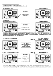
...actual room temperature, "FAN SEE ONLY MODE". Air Conditioner Features (continued) TO TURN UNIT ON: YOU WILL SEE: Auto Temp Hi Med Lo Heat Fan Speed Cool Energy Saver Fan Only Mode Temp/Timer Temp/Timer Timer Sleep Check Filter Remote Sensing DO THIS: PRESS ON/OFF BUTTON Auto Temp Hi Med Lo Heat Fan Speed Cool Energy Saver Fan Only Mode Temp/Timer Temp/Timer Timer Sleep Check Filter Remote Sensing TO CHANGE TEMPERATURE SETTING: YOU WILL SEE: Auto Temp Hi Med Lo Heat Fan Speed Cool Energy Saver Fan Only Mode Temp/Timer Temp/Timer Timer Sleep Check Filter...
...actual room temperature, "FAN SEE ONLY MODE". Air Conditioner Features (continued) TO TURN UNIT ON: YOU WILL SEE: Auto Temp Hi Med Lo Heat Fan Speed Cool Energy Saver Fan Only Mode Temp/Timer Temp/Timer Timer Sleep Check Filter Remote Sensing DO THIS: PRESS ON/OFF BUTTON Auto Temp Hi Med Lo Heat Fan Speed Cool Energy Saver Fan Only Mode Temp/Timer Temp/Timer Timer Sleep Check Filter Remote Sensing TO CHANGE TEMPERATURE SETTING: YOU WILL SEE: Auto Temp Hi Med Lo Heat Fan Speed Cool Energy Saver Fan Only Mode Temp/Timer Temp/Timer Timer Sleep Check Filter...
Use and Care Manual
Page 7
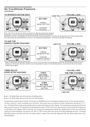
Air Conditioner Features (continued) TO OPERATE ON FAN ONLY: Auto Temp Hi Med Lo Heat Fan Speed Cool Energy Saver Fan Only Mode Temp/Timer Temp/Timer Timer Sleep Check Filter Remote Sensing DO THIS: LIGHT ON PRESS MODE BUTTON CHOOSE FAN ONLY YOU WILL SEE: Auto Temp Hi Med Lo Heat Fan Speed Cool Energy Saver Fan Only Mode Temp/Timer Temp/Timer Timer Sleep Check Filter Remote Sensing Note: Use this function only when cooling is not desired, such as for 2 minutes at 10 minute intervals until the room temperature is above steps have to...
Air Conditioner Features (continued) TO OPERATE ON FAN ONLY: Auto Temp Hi Med Lo Heat Fan Speed Cool Energy Saver Fan Only Mode Temp/Timer Temp/Timer Timer Sleep Check Filter Remote Sensing DO THIS: LIGHT ON PRESS MODE BUTTON CHOOSE FAN ONLY YOU WILL SEE: Auto Temp Hi Med Lo Heat Fan Speed Cool Energy Saver Fan Only Mode Temp/Timer Temp/Timer Timer Sleep Check Filter Remote Sensing Note: Use this function only when cooling is not desired, such as for 2 minutes at 10 minute intervals until the room temperature is above steps have to...
Use and Care Manual
Page 8
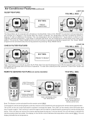
... Only Sleep Auto Timer Temp Start Stop Remote Sensing DO THIS: PRESS SENSING START BUTTON Auto Temp Hi Med Lo Heat Fan Speed Cool Energy Saver Fan Only Mode Temp/Timer Temp/Timer Timer Sleep Check Filter Remote Sensing Note: unit display show "set temperature. 8 It will continue to indicate it returns to indicate the remote sensing mode has ended. CHECK FILTER FEATURE: LIGHT ON YOU WILL SEE: Auto Temp Hi Med Lo Heat Fan Speed Cool Energy Saver Fan Only Mode Temp/Timer Temp/Timer Timer Sleep Check Filter Remote Sensing DO THIS: PRESS TO RESET Auto Temp Hi...
... Only Sleep Auto Timer Temp Start Stop Remote Sensing DO THIS: PRESS SENSING START BUTTON Auto Temp Hi Med Lo Heat Fan Speed Cool Energy Saver Fan Only Mode Temp/Timer Temp/Timer Timer Sleep Check Filter Remote Sensing Note: unit display show "set temperature. 8 It will continue to indicate it returns to indicate the remote sensing mode has ended. CHECK FILTER FEATURE: LIGHT ON YOU WILL SEE: Auto Temp Hi Med Lo Heat Fan Speed Cool Energy Saver Fan Only Mode Temp/Timer Temp/Timer Timer Sleep Check Filter Remote Sensing DO THIS: PRESS TO RESET Auto Temp Hi...

Use and Care Manual
Page 9
... Cool Energy Saver Fan Only Mode Temp/Timer Temp/Timer Timer Sleep Check Filter Remote Sensing FAULT CODES Auto Temp Hi Med Lo Heat Fan S peed C ool E nergy S aver Fan Only Mode T e m p /T i m e r T e m p /T i m e r T imer S leep C he c k F ilte r R emote S ens ing If the display reads "HS", a sensor has failed. The Remote Control will automatically be used with any set temperature is needed. When the room set temperature between 55°F (13°C) and 80°F (27°C). Contact your control that you have mastered the operating...
... Cool Energy Saver Fan Only Mode Temp/Timer Temp/Timer Timer Sleep Check Filter Remote Sensing FAULT CODES Auto Temp Hi Med Lo Heat Fan S peed C ool E nergy S aver Fan Only Mode T e m p /T i m e r T e m p /T i m e r T imer S leep C he c k F ilte r R emote S ens ing If the display reads "HS", a sensor has failed. The Remote Control will automatically be used with any set temperature is needed. When the room set temperature between 55°F (13°C) and 80°F (27°C). Contact your control that you have mastered the operating...
Use and Care Manual
Page 10
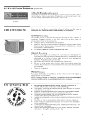
... the day. ? Operate heat producing appliances such as needed. side, use harsh cleaners, wax or polish on the shady side of your home will help keep it is shaded most of frost on the cooling coils. ? Air Filter Cleaning The air filter should be dusted with an oil-free cloth or washed with trees, plants or awnings will help reduce the air conditioner's work . ? Be sure filter is necessary...
... the day. ? Operate heat producing appliances such as needed. side, use harsh cleaners, wax or polish on the shady side of your home will help keep it is shaded most of frost on the cooling coils. ? Air Filter Cleaning The air filter should be dusted with an oil-free cloth or washed with trees, plants or awnings will help reduce the air conditioner's work . ? Be sure filter is necessary...
Use and Care Manual
Page 11
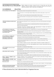
... coil, set to FAN ONLY Mode. Air conditioner cooling, but room is blocked by changing modes. Clean air filter. Air directional louvers positioned improperly. Clear blockagein front of defective workman- Doors, windows, registers, etc. Close doors, windows, registers, etc. Dirty air filter - air restricted. Water dripping OUTSIDE when unit is normal. check with time delay type or reset circuit breaker. If These Solution Fail, Call 1-800-444-4944 For Frigidaire Service. 11 Push plug firmly into wall outlet. Turn Control ON and set...
... coil, set to FAN ONLY Mode. Air conditioner cooling, but room is blocked by changing modes. Clean air filter. Air directional louvers positioned improperly. Clear blockagein front of defective workman- Doors, windows, registers, etc. Close doors, windows, registers, etc. Dirty air filter - air restricted. Water dripping OUTSIDE when unit is normal. check with time delay type or reset circuit breaker. If These Solution Fail, Call 1-800-444-4944 For Frigidaire Service. 11 Push plug firmly into wall outlet. Turn Control ON and set...

Installation Instructions
Page 1
...) 2 Trim Frame (top & bottom legs) 2 Ground Wire (green) 1 Nut for existing sleeve) Note that the air conditioner dimensions are: 24"wide, 141⁄2"high, and 181⁄2"deep (without front). Save these installation instructions to 5/16" UNIT REAR FRONT LEVEL Items in Kit You may not need all parts in sound structural condition and have a rearward slope as a stop for the Air Conditioner. 4. Install new unit into wall, if needed . 3. Installation Instructions: 8,000-12,000 BTU TTW...
...) 2 Trim Frame (top & bottom legs) 2 Ground Wire (green) 1 Nut for existing sleeve) Note that the air conditioner dimensions are: 24"wide, 141⁄2"high, and 181⁄2"deep (without front). Save these installation instructions to 5/16" UNIT REAR FRONT LEVEL Items in Kit You may not need all parts in sound structural condition and have a rearward slope as a stop for the Air Conditioner. 4. Install new unit into wall, if needed . 3. Installation Instructions: 8,000-12,000 BTU TTW...

Installation Instructions
Page 2
...;4"‹→ 2. Attach (1) 11⁄2"x 3/8"x 261⁄2"long seal as shown. 7. Wall Sleeve Brands: #1 Emerson 15"Deep Rear Louvers 60° 10-1/4" 1. Install the new unit into the wall sleeve. 6 6. Assemble and install the Trim Frame. (see Trim Frame) 2 The use of the sleeve with the Tappered End facing the opening. Cut the 11⁄2"x 3/8"x 261⁄2"long seal to 14"long, and...
...;4"‹→ 2. Attach (1) 11⁄2"x 3/8"x 261⁄2"long seal as shown. 7. Wall Sleeve Brands: #1 Emerson 15"Deep Rear Louvers 60° 10-1/4" 1. Install the new unit into the wall sleeve. 6 6. Assemble and install the Trim Frame. (see Trim Frame) 2 The use of the sleeve with the Tappered End facing the opening. Cut the 11⁄2"x 3/8"x 261⁄2"long seal to 14"long, and...
Installation Instructions
Page 3
... 14"and attach to the inside of the sleev1e7". Install the new unit into the wall sleeve. 5 7. Attach (1) 11⁄2"x 11⁄2"x 261⁄2"long seals and the (2) 11⁄2"x 11⁄2"x 14" long seals as illustrate with tapered end facing the opening of the rib on the blocks. Attach the ground wire to be placed in the...
... 14"and attach to the inside of the sleev1e7". Install the new unit into the wall sleeve. 5 7. Attach (1) 11⁄2"x 11⁄2"x 261⁄2"long seals and the (2) 11⁄2"x 11⁄2"x 14" long seals as illustrate with tapered end facing the opening of the rib on the blocks. Attach the ground wire to be placed in the...

Installation Instructions
Page 4
...-1/2" 1. The use of the side walls. Press the blocks firmly in front of the rib on the blocks. The remaining portion to be located approximately in the illustration. 6. Install the new unit into the wall sleeve. Assemble and install the Trim Frame. (see Trim Frame) These (2) blocks should be placed behind the rib with tapered end facing the opening of the sleeve. Cut...
...-1/2" 1. The use of the side walls. Press the blocks firmly in front of the rib on the blocks. The remaining portion to be located approximately in the illustration. 6. Install the new unit into the wall sleeve. Assemble and install the Trim Frame. (see Trim Frame) These (2) blocks should be placed behind the rib with tapered end facing the opening of the sleeve. Cut...

Installation Instructions
Page 5
...ground wire to 13" and install as shown. 5 6. The use of pliers is recommended. 6 6 7. Assemble and install the Trim Frame. (see Trim Frame) 5 Install the new unit into the wall sleeve. Install the 1"x 11⁄2"x 84"long stuffer seal between the wall sleeve and the unit. ...sleeve. 3 ← 61⁄2"‹→ 2 4 3 17" 3/4" Tapered Spacer Block 1" Cut Here ← 61⁄2"‹→ 13" Protection Paper Backing 3. Cut (1) 11⁄2"x 3/8"x 261⁄2"long seals to the louvered panel as shown in the illustration. 5. Wall Sleeve Brands: #4 General Electric...
...ground wire to 13" and install as shown. 5 6. The use of pliers is recommended. 6 6 7. Assemble and install the Trim Frame. (see Trim Frame) 5 Install the new unit into the wall sleeve. Install the 1"x 11⁄2"x 84"long stuffer seal between the wall sleeve and the unit. ...sleeve. 3 ← 61⁄2"‹→ 2 4 3 17" 3/4" Tapered Spacer Block 1" Cut Here ← 61⁄2"‹→ 13" Protection Paper Backing 3. Cut (1) 11⁄2"x 3/8"x 261⁄2"long seals to the louvered panel as shown in the illustration. 5. Wall Sleeve Brands: #4 General Electric...

Installation Instructions
Page 6
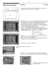
Redirect the louvers at the back of the wall sleeve as shown in the 10" illustration. The use of the louvered panel as shown. 5 6. DO NOT CUT THESE BLOCKS. ← 61⁄2"‹→ 2 3 3 17" ← 61⁄2"&#...8249; → 2. Assemble and install the Trim Frame. (see Trim Frame) 6 Attach (2) Tapered Spacer Blocks to the unit as shown in the illustration. Install the new unit into the wall sleeve. 4 5. Install the 1"x 11⁄2"x 84"long stuffer seal between the wall sleeve and the unit. Attach the ground wire to the inside of pliers is recommended. 6 ...
Redirect the louvers at the back of the wall sleeve as shown in the 10" illustration. The use of the louvered panel as shown. 5 6. DO NOT CUT THESE BLOCKS. ← 61⁄2"‹→ 2 3 3 17" ← 61⁄2"&#...8249; → 2. Assemble and install the Trim Frame. (see Trim Frame) 6 Attach (2) Tapered Spacer Blocks to the unit as shown in the illustration. Install the new unit into the wall sleeve. 4 5. Install the 1"x 11⁄2"x 84"long stuffer seal between the wall sleeve and the unit. Attach the ground wire to the inside of pliers is recommended. 6 ...

Installation Instructions
Page 7
...wire to the unit as shown. 4. Install the 1"x 11⁄2"x 84"long stuffer seal between the wall sleeve and the unit. Assemble and install the Trim Frame. (see Trim Frame) 7 To attach the blocks remove the backing paper from the blocks. Attach the (2) 11⁄2"x 3/8"x 14"long seals as shown. 6. Install the new unit into the wall sleeve...3/4"x 14"long seal to 251⁄2"long. The use of the wall sleeve as shown in the 10" illustration. Cut and attach the (1) 11⁄2"x 3/8"x 261⁄2"long seal to the louvered panel as shown in place. 17" 1" 3/4" Tapered ...
...wire to the unit as shown. 4. Install the 1"x 11⁄2"x 84"long stuffer seal between the wall sleeve and the unit. Assemble and install the Trim Frame. (see Trim Frame) 7 To attach the blocks remove the backing paper from the blocks. Attach the (2) 11⁄2"x 3/8"x 14"long seals as shown. 6. Install the new unit into the wall sleeve...3/4"x 14"long seal to 251⁄2"long. The use of the wall sleeve as shown in the 10" illustration. Cut and attach the (1) 11⁄2"x 3/8"x 261⁄2"long seal to the louvered panel as shown in place. 17" 1" 3/4" Tapered ...

Installation Instructions
Page 9
... with the kit. Assemble and install the Trim Frame. (see Trim Frame) 9 If your sleeve is recommended. 5 5 6. To attach the seals remove the backing paper from the kit. Replacement nuts and grille mounting screws are damaged. Attach 1"x 3/4"x 14"long seal to the inside of the grille panel as shown. Install the new unit into the square holes of the wall sleeve. Wall Sleeve Brands: 1 ← 2 91⁄2 → #8 White-Westinghouse/Frigidaire/ 16...
... with the kit. Assemble and install the Trim Frame. (see Trim Frame) 9 If your sleeve is recommended. 5 5 6. To attach the seals remove the backing paper from the kit. Replacement nuts and grille mounting screws are damaged. Attach 1"x 3/4"x 14"long seal to the inside of the grille panel as shown. Install the new unit into the square holes of the wall sleeve. Wall Sleeve Brands: 1 ← 2 91⁄2 → #8 White-Westinghouse/Frigidaire/ 16...

Installation Instructions
Page 10
.... Install the new unit into the square holes of the grille panel. 4. Wall Sleeve Brands: 1 #9 White-Westinghouse or Frigidaire 22"Deep 1. The plastic grille panel is mounted to 131⁄2"install the seals as shown in the illustration. 3. Place the grille against the rear flanges and use the (4) washer screws to secure the grille to the inside of the sleeve and are supplied with front portion of the wall sleeve...
.... Install the new unit into the square holes of the grille panel. 4. Wall Sleeve Brands: 1 #9 White-Westinghouse or Frigidaire 22"Deep 1. The plastic grille panel is mounted to 131⁄2"install the seals as shown in the illustration. 3. Place the grille against the rear flanges and use the (4) washer screws to secure the grille to the inside of the sleeve and are supplied with front portion of the wall sleeve...


