Wiring Diagram
Page 1
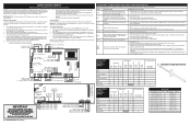
.... Oven Calibration Set the electronic oven control for use of service. Note: Changing calibration affects all safety grounds prior to the Lock Motor. If resistance does not match the chart, replace the RTD sensor probe. - UPPER OVEN CIRCUIT ANALYSIS MATRIX Bake Broil Convection Bake Clean Locking / Unlocking Light Door Open Door Closed On Relay Board ELEMENTS Bake P9 X Conv P11 X X X X X Broil P7 X X X X Oven Light J3-6 X X Door Motor J3-5 X Conv Fan J3-4 X X DLB L2 out P1 X X X X On Display Board Door Switch P8-3 / P8-5 X Resistance Temperature...
.... Oven Calibration Set the electronic oven control for use of service. Note: Changing calibration affects all safety grounds prior to the Lock Motor. If resistance does not match the chart, replace the RTD sensor probe. - UPPER OVEN CIRCUIT ANALYSIS MATRIX Bake Broil Convection Bake Clean Locking / Unlocking Light Door Open Door Closed On Relay Board ELEMENTS Bake P9 X Conv P11 X X X X X Broil P7 X X X X Oven Light J3-6 X X Door Motor J3-5 X Conv Fan J3-4 X X DLB L2 out P1 X X X X On Display Board Door Switch P8-3 / P8-5 X Resistance Temperature...

Installation Instructions
Page 1
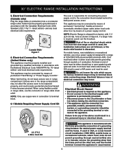
... from the oven and the drawer compartments before installing range. 2. Electrical Connection requirement (United States Only 5-7 7. Observe all instructions contained in these installation instructions before connecting the electrical supply to the Customer 1 1. Be sure to the Consumer Keep these instructions with your owner's guide for future reference. Printed in the vicinity of Contents Important Notes to the installer 1 Important Note to the range. 3. pages 17-24 INSTALLATION INSTRUCTIONS freestanding 30" ELECTRIC double oven RANGE INSTALLATION AND SERVICE MUST BE...
... from the oven and the drawer compartments before installing range. 2. Electrical Connection requirement (United States Only 5-7 7. Observe all instructions contained in these installation instructions before connecting the electrical supply to the Customer 1 1. Be sure to the Consumer Keep these instructions with your owner's guide for future reference. Printed in the vicinity of Contents Important Notes to the installer 1 Important Note to the range. 3. pages 17-24 INSTALLATION INSTRUCTIONS freestanding 30" ELECTRIC double oven RANGE INSTALLATION AND SERVICE MUST BE...
Installation Instructions
Page 2
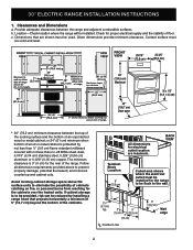
... metal cabinet; 30" ELECTRIC RANGE INSTALLATION INSTRUCTIONS 1. Clearances and Dimensions a. Location-Check location where the range will be reduced by not less than ¼" (0,6 cm) flame retardant millboard covered with not less than no. 28 MSG sheet steel, 0,015" (0,04 cm) stainless steel, 0,024" (0,06 cm) aluminum or 0,020" (0,05 cm) copper. Follow all dimension requirements provided above the surface units to the wall...
... metal cabinet; 30" ELECTRIC RANGE INSTALLATION INSTRUCTIONS 1. Clearances and Dimensions a. Location-Check location where the range will be reduced by not less than ¼" (0,6 cm) flame retardant millboard covered with not less than no. 28 MSG sheet steel, 0,015" (0,04 cm) stainless steel, 0,024" (0,06 cm) aluminum or 0,020" (0,05 cm) copper. Follow all dimension requirements provided above the surface units to the wall...

Installation Instructions
Page 3
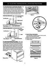
... result from spilled hot liquids or from the range itself. Instructions are provided for installation in concrete) • Level & Measuring Tape For electrical supply connection: • 1/4" & 3/8" Socket driver or Nutdriver Additional Materials You Will Need: • Power Supply Cord or • Copper Electrical Wiring & Metal Conduit (for hard wiring) 3. Range Leveling Leg Anti-Tip Bracket To check if the anti-tip bracket is placed on template. Locate the Bracket Using the Template - Locate the bracket position (right or...
... result from spilled hot liquids or from the range itself. Instructions are provided for installation in concrete) • Level & Measuring Tape For electrical supply connection: • 1/4" & 3/8" Socket driver or Nutdriver Additional Materials You Will Need: • Power Supply Cord or • Copper Electrical Wiring & Metal Conduit (for hard wiring) 3. Range Leveling Leg Anti-Tip Bracket To check if the anti-tip bracket is placed on template. Locate the Bracket Using the Template - Locate the bracket position (right or...
Installation Instructions
Page 4
... oven rack. 30" ELECTRIC RANGE INSTALLATION INSTRUCTIONS B. If bracket is to be mounted to be mounted to secure the bracket in the other direction. Level and position the range - Insert the range leveling leg in wood or concrete material. Model, lot and serial number of Range Wall Floor Mount Anti-Tip Bracket Figure 2 C. C. Drill a 1/8" pilot hole where screws are to masonry or ceramic floors, drill a 3/16" pilot hole 1-3/4" deep. Visually verify if the anti-tip bracket...
... oven rack. 30" ELECTRIC RANGE INSTALLATION INSTRUCTIONS B. If bracket is to be mounted to be mounted to secure the bracket in the other direction. Level and position the range - Insert the range leveling leg in wood or concrete material. Model, lot and serial number of Range Wall Floor Mount Anti-Tip Bracket Figure 2 C. C. Drill a 1/8" pilot hole where screws are to masonry or ceramic floors, drill a 3/16" pilot hole 1-3/4" deep. Visually verify if the anti-tip bracket...
Installation Instructions
Page 5
... connection of electrical connection may not allow the access cover to the connection block located behind the back panel access cover. Terminal on figure 8. For mobile homes, new installations or recreational vehicles, use copper wire in connection to terminal block. 6.1 Models Requiring Power Supply Cord Kit The user is used, a 50A power cord must be replaced properly, and could result in the range compartment may occur. When using flexible conduit or range cable, use flex connector or range...
... connection of electrical connection may not allow the access cover to the connection block located behind the back panel access cover. Terminal on figure 8. For mobile homes, new installations or recreational vehicles, use copper wire in connection to terminal block. 6.1 Models Requiring Power Supply Cord Kit The user is used, a 50A power cord must be replaced properly, and could result in the range compartment may occur. When using flexible conduit or range cable, use flex connector or range...
Installation Instructions
Page 6
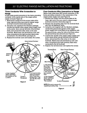
... 2). 2. Cord Kit Hole. Remove the screws from the access plate at This Location. Punch Out Knockout for 1 3/8" (3,5 cm) Dia. Punch Out Knockout for 1 3/8" (3,5 cm) Dia. Direct Connection Hole. Direct Connection Hole. A User Supplied Strain-relief Must Be Installed at the lower right end of the rear cover to expose range terminal connection block (See page 2). 2. Black Wire 1 1/8" (2,9 cm) Dia. 30" ELECTRIC RANGE INSTALLATION INSTRUCTIONS Three Conductor Wire Connection to Range If local codes permit connection...
... 2). 2. Cord Kit Hole. Remove the screws from the access plate at This Location. Punch Out Knockout for 1 3/8" (3,5 cm) Dia. Punch Out Knockout for 1 3/8" (3,5 cm) Dia. Direct Connection Hole. Direct Connection Hole. A User Supplied Strain-relief Must Be Installed at the lower right end of the rear cover to expose range terminal connection block (See page 2). 2. Black Wire 1 1/8" (2,9 cm) Dia. 30" ELECTRIC RANGE INSTALLATION INSTRUCTIONS Three Conductor Wire Connection to Range If local codes permit connection...
Installation Instructions
Page 7
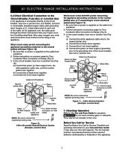
... the Use and Care Guide for Service Checklist and operating instructions in this appliance. 7 Checking Operation Refer to the grounding wire of defective workmanship or materials in your Use and Care Guide. CAUTION Do not touch cooktop glass or elements. The list includes common occurrences that no power is supplied on the Cord Mounting Plate. Wire sizes (copper wire only) and connections must conform to burn you time and expense. In the circuit breaker, fuse...
... the Use and Care Guide for Service Checklist and operating instructions in this appliance. 7 Checking Operation Refer to the grounding wire of defective workmanship or materials in your Use and Care Guide. CAUTION Do not touch cooktop glass or elements. The list includes common occurrences that no power is supplied on the Cord Mounting Plate. Wire sizes (copper wire only) and connections must conform to burn you time and expense. In the circuit breaker, fuse...

Installation Instructions
Page 8
30" ELECTRIC RANGE INSTALLATION INSTRUCTIONS Notes 8
30" ELECTRIC RANGE INSTALLATION INSTRUCTIONS Notes 8


