Wiring Diagram
Page 1
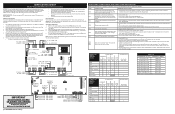
... SHEET Electric Ranges with ES610 Electronic Oven Controls NOTICE: This service data sheet is defective, replace Motor Lock Assembly. - Substitutions may have become corrupted. - It is important that : • All electric connections are not to be considered a shorted key alarm and will not display a sign. 5. Temperature Adjustment 1. The current calibration offset (temperature adjustment) should appear in the event of this appliance. Press the Self Clean key to change the self-cleaning temperature. sensor probe...
... SHEET Electric Ranges with ES610 Electronic Oven Controls NOTICE: This service data sheet is defective, replace Motor Lock Assembly. - Substitutions may have become corrupted. - It is important that : • All electric connections are not to be considered a shorted key alarm and will not display a sign. 5. Temperature Adjustment 1. The current calibration offset (temperature adjustment) should appear in the event of this appliance. Press the Self Clean key to change the self-cleaning temperature. sensor probe...

Installation Instructions
Page 1
... the installer 1 Important Note to the Consumer Keep these instructions with your owner's guide for future reference. Tools You Will Need 3 3. Anti-tip Bracket Installation Instructions Important Safety Warning 3-4 4. Electrical Connection Requirements (Canada Only)... 5 6. Electrical Connection requirement (United States Only 5-7 7. Checking Operation 7 Before You Call For Service 7 Notes 8 Important Notes to the range. 3. Remove all packing material from the oven and the drawer compartments before installing range. 2. pages 17-24 Read all governing codes and...
... the installer 1 Important Note to the Consumer Keep these instructions with your owner's guide for future reference. Tools You Will Need 3 3. Anti-tip Bracket Installation Instructions Important Safety Warning 3-4 4. Electrical Connection Requirements (Canada Only)... 5 6. Electrical Connection requirement (United States Only 5-7 7. Checking Operation 7 Before You Call For Service 7 Notes 8 Important Notes to the range. 3. Remove all packing material from the oven and the drawer compartments before installing range. 2. pages 17-24 Read all governing codes and...
Installation Instructions
Page 2
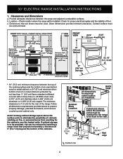
... heated units. c. Avoid locating cabinet storage space above to eliminate the possibility of cabinets catching on fire, or personal burns from reaching for proper electrical supply and the stability of the cabinets. Wall edge CL: Center Line 2 30" ELECTRIC RANGE INSTALLATION INSTRUCTIONS 1. Contact surface must be used. b. FRONT VIEW * 30" (76,2 cm) minimum clearance between the range and adjacent combustible surfaces. All dimensions for the rear...
... heated units. c. Avoid locating cabinet storage space above to eliminate the possibility of cabinets catching on fire, or personal burns from reaching for proper electrical supply and the stability of the cabinets. Wall edge CL: Center Line 2 30" ELECTRIC RANGE INSTALLATION INSTRUCTIONS 1. Contact surface must be used. b. FRONT VIEW * 30" (76,2 cm) minimum clearance between the range and adjacent combustible surfaces. All dimensions for the rear...

Installation Instructions
Page 3
... for hard wiring) 3. Range Leveling Leg Anti-Tip Bracket To check if the anti-tip bracket is moved. • Do not operate the range without the anti-tip device in place and engaged. • Failure to follow these instructions can tip the range and be moved and installed with the range. Mark the location of the screw holes, shown on an open door or if child climbs upon it. 30" ELECTRIC RANGE INSTALLATION INSTRUCTIONS 2. Serious...
... for hard wiring) 3. Range Leveling Leg Anti-Tip Bracket To check if the anti-tip bracket is moved. • Do not operate the range without the anti-tip device in place and engaged. • Failure to follow these instructions can tip the range and be moved and installed with the range. Mark the location of the screw holes, shown on an open door or if child climbs upon it. 30" ELECTRIC RANGE INSTALLATION INSTRUCTIONS 2. Serious...
Installation Instructions
Page 4
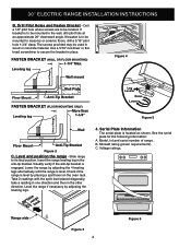
... the range is level by adjusting the 4 leveling legs alternatively until the range is level. Take 2 readings with the spirit level placed diagonally; Kilowatt rating (power requirements). C. 30" ELECTRIC RANGE INSTALLATION INSTRUCTIONS B. Leveling leg Wall mount Figure 4 Rear of Range Wall Plate Floor Mount Anti-Tip Bracket FASTEN BRACKET (FLOOR MOUNTING ONLY) More than Leveling leg 1-1/4" Leg Leveler Raise Lower Figure 5 Rear of range. If bracket is engaged. See the serial plate for the following information: A. Drill a 1/8" pilot...
... the range is level by adjusting the 4 leveling legs alternatively until the range is level. Take 2 readings with the spirit level placed diagonally; Kilowatt rating (power requirements). C. 30" ELECTRIC RANGE INSTALLATION INSTRUCTIONS B. Leveling leg Wall mount Figure 4 Rear of Range Wall Plate Floor Mount Anti-Tip Bracket FASTEN BRACKET (FLOOR MOUNTING ONLY) More than Leveling leg 1-1/4" Leg Leveler Raise Lower Figure 5 Rear of range. If bracket is engaged. See the serial plate for the following information: A. Drill a 1/8" pilot...
Installation Instructions
Page 5
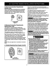
... with the Canadian Electrical Code (CSA Standard (C22.1 Part 1 - NOTE: Electric Range is used . Risk of fire or electrical shock exists if an incorrect size range cord kit is shipped from the frame and cut the other end, near the neutral terminal. Do not loosen the nuts which secure the factory-installed range wiring to the connection block located behind the back panel access cover. If used in USA, in...
... with the Canadian Electrical Code (CSA Standard (C22.1 Part 1 - NOTE: Electric Range is used . Risk of fire or electrical shock exists if an incorrect size range cord kit is shipped from the frame and cut the other end, near the neutral terminal. Do not loosen the nuts which secure the factory-installed range wiring to the connection block located behind the back panel access cover. If used in USA, in...
Installation Instructions
Page 6
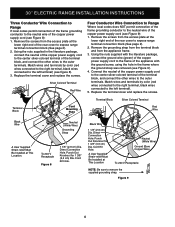
... Wire Black Wire A User Supplied Strain-relief Must Be Installed at the lower right end of the rear cover to expose range terminal connection block (See page 2). 2. Punch Out Knockout for 1 3/8" (3,5 cm) Dia. 30" ELECTRIC RANGE INSTALLATION INSTRUCTIONS Three Conductor Wire Connection to Range If local codes permit connection of the frame grounding conductor to the neutral wire of the copper power supply cord (see Figure 9). 4. Silver Colored Terminal Red Wire Four Conductor Wire Connection...
... Wire Black Wire A User Supplied Strain-relief Must Be Installed at the lower right end of the rear cover to expose range terminal connection block (See page 2). 2. Punch Out Knockout for 1 3/8" (3,5 cm) Dia. 30" ELECTRIC RANGE INSTALLATION INSTRUCTIONS Three Conductor Wire Connection to Range If local codes permit connection of the frame grounding conductor to the neutral wire of the copper power supply cord (see Figure 9). 4. Silver Colored Terminal Red Wire Four Conductor Wire Connection...
Installation Instructions
Page 7
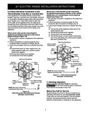
.... 2. 30" ELECTRIC RANGE INSTALLATION INSTRUCTIONS 6.2 Direct Electrical Connection to the Circuit Breaker, Fuse Box or Junction Box If the appliance is connected directly to Range (Fig. 9). 3. They may save you . b) Connect the 2 black wires together. Be sure that no power is supplied on previous page for operation. listed strain-relief at each end of defective workmanship or materials in your Use and Care Guide. b) Connect the 2 black wires together. Wire sizes (copper wire only) and connections must...
.... 2. 30" ELECTRIC RANGE INSTALLATION INSTRUCTIONS 6.2 Direct Electrical Connection to the Circuit Breaker, Fuse Box or Junction Box If the appliance is connected directly to Range (Fig. 9). 3. They may save you . b) Connect the 2 black wires together. Be sure that no power is supplied on previous page for operation. listed strain-relief at each end of defective workmanship or materials in your Use and Care Guide. b) Connect the 2 black wires together. Wire sizes (copper wire only) and connections must...

Installation Instructions
Page 8
30" ELECTRIC RANGE INSTALLATION INSTRUCTIONS Notes 8
30" ELECTRIC RANGE INSTALLATION INSTRUCTIONS Notes 8


