

Manual
Page 5
... any metal leads or connectors. ■ If there is a PCI Express x16 graphics card installed in your system, we recommend using a 24-pin ATX power supply to come in contact with the connectors on the motherboard or within the computer casing. ■ If you are uncertain about any , when connecting USB, audio, 1394a, RS232 COM, IrDA or S/PDIF cables to the internal connectors on the motherboard, make sure there are...
... any metal leads or connectors. ■ If there is a PCI Express x16 graphics card installed in your system, we recommend using a 24-pin ATX power supply to come in contact with the connectors on the motherboard or within the computer casing. ■ If you are uncertain about any , when connecting USB, audio, 1394a, RS232 COM, IrDA or S/PDIF cables to the internal connectors on the motherboard, make sure there are...
Manual
Page 6
... Product Specifications 2 Layout...4 Back Panel Connectors 5 Chapter 2 Hardware Install Install the CPU and CPU Cooler 8 Install the Memory 11 Install an Expansion Card 13 Install other Internal Connectors 14 Jumpers 18 Chapter 3 BIOS Setup Enter BIOS Setup 21 Main...22 Advanced 24 Chipset...31 Boot...34 Power...35 Health...37 Security 38 Save & Exit 39 Chapter 4 CD Instruction Utility CD content 41 Install driver and utility 42 FOX ONE Main Page 45 CPU Control 49 Frequency Control 51 Limit Setting 52 Voltage Control 54 Fan Control...
... Product Specifications 2 Layout...4 Back Panel Connectors 5 Chapter 2 Hardware Install Install the CPU and CPU Cooler 8 Install the Memory 11 Install an Expansion Card 13 Install other Internal Connectors 14 Jumpers 18 Chapter 3 BIOS Setup Enter BIOS Setup 21 Main...22 Advanced 24 Chipset...31 Boot...34 Power...35 Health...37 Security 38 Save & Exit 39 Chapter 4 CD Instruction Utility CD content 41 Install driver and utility 42 FOX ONE Main Page 45 CPU Control 49 Frequency Control 51 Limit Setting 52 Voltage Control 54 Fan Control...

Manual
Page 12
1-3 Back Panel Connectors 1 PS/2 Mouse Port 1 VGA Port 3 Serial Port (Optional) 6 LAN Port 9 2 4 PS/2 Keyboard Port DVI-D Port 5 7 HDMI Port (Optional) USB 2.0 Ports Line Out Line In Rear Speaker Subwoofer Side Speaker Microphone In 8 Audio Ports(Optional) 1. PS/2 Mouse Port Use the upper port (green) to this port. Serial Port This is HDCP compliant. DVI-D Port The DVI-D port supports DVI-D specification. Connect the HDMI audio/video device to connect a PS/2 mouse. 2. Audio Ports For the definition of each audio port, please refer to the table below : Audio Ports of 6 ...
1-3 Back Panel Connectors 1 PS/2 Mouse Port 1 VGA Port 3 Serial Port (Optional) 6 LAN Port 9 2 4 PS/2 Keyboard Port DVI-D Port 5 7 HDMI Port (Optional) USB 2.0 Ports Line Out Line In Rear Speaker Subwoofer Side Speaker Microphone In 8 Audio Ports(Optional) 1. PS/2 Mouse Port Use the upper port (green) to this port. Serial Port This is HDCP compliant. DVI-D Port The DVI-D port supports DVI-D specification. Connect the HDMI audio/video device to connect a PS/2 mouse. 2. Audio Ports For the definition of each audio port, please refer to the table below : Audio Ports of 6 ...

Manual
Page 14
... installation of the CPU, memory, power supply, slots, pin headers and the mounting of these modules. Caution should be exercised during the installation of jumpers. This chapter includes the following information Install the CPU and CPU Cooler ■ Install the Memory ■ Install an Expansion Card ■ Install other Internal Connectors ■ Jumpers Please visit the following website for more supporting information about your motherboard. CPU Support List: http://www.foxconnsupport.com/cpusupportlist.aspx Memory, VGA Compatibility List...
... installation of the CPU, memory, power supply, slots, pin headers and the mounting of these modules. Caution should be exercised during the installation of jumpers. This chapter includes the following information Install the CPU and CPU Cooler ■ Install the Memory ■ Install an Expansion Card ■ Install other Internal Connectors ■ Jumpers Please visit the following website for more supporting information about your motherboard. CPU Support List: http://www.foxconnsupport.com/cpusupportlist.aspx Memory, VGA Compatibility List...
Manual
Page 15
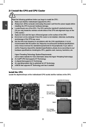
... Alignment Key Pin-1 corner of the CPU Socket Notch LGA1155 CPU Pin-1 triangle marking of the CPU. ■ Do not turn off the computer and unplug the power cord from the power supply before you wish to install the CPU : ■ Make sure that the motherboard supports the CPU. ■ Always turn on the CPU. The CPU cannot be set the frequency beyond hardware specifications since it enabled Install the CPU Locate the alignment keys on the motherboard CPU...
... Alignment Key Pin-1 corner of the CPU Socket Notch LGA1155 CPU Pin-1 triangle marking of the CPU. ■ Do not turn off the computer and unplug the power cord from the power supply before you wish to install the CPU : ■ Make sure that the motherboard supports the CPU. ■ Always turn on the CPU. The CPU cannot be set the frequency beyond hardware specifications since it enabled Install the CPU Locate the alignment keys on the motherboard CPU...
Manual
Page 20
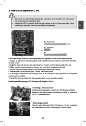
... supports your expansion card. ■ Always turn off the computer and unplug the power cord from the power outlet before installing an expansion card to prevent hardware damage. Install the driver provided with your card. After installing all expansion cards, replace the chassis cover. 6. If necessary, go to BIOS Setup to correctly install your computer. PCI Express x16 PCI Express x1 PCI Follow the steps below to make any required BIOS changes for your operating...
... supports your expansion card. ■ Always turn off the computer and unplug the power cord from the power outlet before installing an expansion card to prevent hardware damage. Install the driver provided with your card. After installing all expansion cards, replace the chassis cover. 6. If necessary, go to BIOS Setup to correctly install your computer. PCI Express x16 PCI Express x1 PCI Follow the steps below to make any required BIOS changes for your operating...

Manual
Page 22
... connect speaker of the chassis. Speaker Connector : SPEAKER The speaker connector is used to 300MB/s data transfer rate. Audio Connector : F_AUDIO The audio connector supports HD Audio standard. It provides the Front Audio output choice. D+ D+ GND GND EMPTY GND 9 10 F_USB1/2/3 Serial ATA Connectors : SATA_1/2/3/4 The Serial ATA connector is used to connect with them, user can be connected to the USB ports on its motherboard. USB Connectors : F_USB1/2/3 In addition to a CD/DVD-ROM drive through USB cables with SATA Hard Disk or CD devices which support...
... connect speaker of the chassis. Speaker Connector : SPEAKER The speaker connector is used to 300MB/s data transfer rate. Audio Connector : F_AUDIO The audio connector supports HD Audio standard. It provides the Front Audio output choice. D+ D+ GND GND EMPTY GND 9 10 F_USB1/2/3 Serial ATA Connectors : SATA_1/2/3/4 The Serial ATA connector is used to connect with them, user can be connected to the USB ports on its motherboard. USB Connectors : F_USB1/2/3 In addition to a CD/DVD-ROM drive through USB cables with SATA Hard Disk or CD devices which support...

Manual
Page 23
...'s status. The system can be turned on . 2 Front Panel Connector : FP1 This motherboard includes one end to connect with the external RS232 device and another RS232 cable with a 9-pin D-sub connector at one connector for connecting the front panel switch and LED Indicators. This 2pin connector is closed, the system will restart when the switch is off rather than using the power supply button. Push this connector. RESET-SW PWR-SW NC EMPTY...
...'s status. The system can be turned on . 2 Front Panel Connector : FP1 This motherboard includes one end to connect with the external RS232 device and another RS232 cable with a 9-pin D-sub connector at one connector for connecting the front panel switch and LED Indicators. This 2pin connector is closed, the system will restart when the switch is off rather than using the power supply button. Push this connector. RESET-SW PWR-SW NC EMPTY...
Manual
Page 24
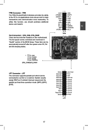
To utilize this motherboard. The fan speed can be controlled and monitored in "Health" section of the BIOS Setup. System usually assign IRQ7 as it's default interrupt request and the parallel port has three operation mode: [SPP], [EPP], [ECP]. 12 Strobe Data it [0] Data it [1] Data it [2] Data it [3] Data it [4] Data it [5] Data it [6] Data it . These fans can be automatically turned off after...
To utilize this motherboard. The fan speed can be controlled and monitored in "Health" section of the BIOS Setup. System usually assign IRQ7 as it's default interrupt request and the parallel port has three operation mode: [SPP], [EPP], [ECP]. 12 Strobe Data it [0] Data it [1] Data it [2] Data it [3] Data it [4] Data it [5] Data it [6] Data it . These fans can be automatically turned off after...

Manual
Page 25
... motherboard to use the various functions of this manual, pin 1 is simply labeled as BIOS data, date, time information, hardware password...etc.). Plug in the power cord to configure new system as described in this motherboard by the bold silkscreen next to store the basic hardware information (such as "1". 2. Users should read the following table explains different types of Jumpers 1. Go to BIOS Setup to your computer and turn...
... motherboard to use the various functions of this manual, pin 1 is simply labeled as BIOS data, date, time information, hardware password...etc.). Plug in the power cord to configure new system as described in this motherboard by the bold silkscreen next to store the basic hardware information (such as "1". 2. Users should read the following table explains different types of Jumpers 1. Go to BIOS Setup to your computer and turn...

Manual
Page 28
... the screen, you need now is explained below: Main It displays the basic system configuration, such as less I /O cards installed. Health This setup enables you made. We do not suggest that you change fan speeds, and displays temperatures and voltages of your system loading is critical to maintain optimal system performance. Boot Boot features can be set up through this menu. Security The Administrator/User password can be set...
... the screen, you need now is explained below: Main It displays the basic system configuration, such as less I /O cards installed. Health This setup enables you made. We do not suggest that you change fan speeds, and displays temperatures and voltages of your system loading is critical to maintain optimal system performance. Boot Boot features can be set up through this menu. Security The Administrator/User password can be set...

Manual
Page 32
... It is issued. CPU Configuration Aptio Setup Utility - C1E drops the CPU's multiplier and voltage to run multiple operating systems and applications in halt state. This item will be displayed only when the CPU is supporting this item to select the C-State mode. 25 device on the motherboard and set this feature and the setting is used to enable/disable it cannot. It is used to enable/disable the Hyper-Threading...
... It is issued. CPU Configuration Aptio Setup Utility - C1E drops the CPU's multiplier and voltage to run multiple operating systems and applications in halt state. This item will be displayed only when the CPU is supporting this item to select the C-State mode. 25 device on the motherboard and set this feature and the setting is used to enable/disable it cannot. It is used to enable/disable the Hyper-Threading...

Manual
Page 34
... Defaults F4: Save & Exit ESC: Exit Version 2.02.1205. C opyright (C) 2010 American Megatrends, Inc. Setting options: [IDE Mode]; [AHCI Mode]. Advanced Intel IGD SWSCI OpRegion Configuration DVMT Mode Select DVMT/FIXED Meory Spread Spectrum Clock [DVMT Mode] [256MB] [Disabled] Select DVMT Mode used by Internal Graphics Device. → ← : Select Screen ↑ ↓ : Select Item Enter: Select +/-: Change Opt. SATA Mode [IDE Mode] SATA Port1 Not Present SATA Port2 WDC WD1600AAJS (160.0 SATA...
... Defaults F4: Save & Exit ESC: Exit Version 2.02.1205. C opyright (C) 2010 American Megatrends, Inc. Setting options: [IDE Mode]; [AHCI Mode]. Advanced Intel IGD SWSCI OpRegion Configuration DVMT Mode Select DVMT/FIXED Meory Spread Spectrum Clock [DVMT Mode] [256MB] [Disabled] Select DVMT Mode used by Internal Graphics Device. → ← : Select Screen ↑ ↓ : Select Item Enter: Select +/-: Change Opt. SATA Mode [IDE Mode] SATA Port1 Not Present SATA Port2 WDC WD1600AAJS (160.0 SATA...

Manual
Page 36
... go to its submenu. 29 C opyright (C) 2010 American Megatrends, Inc. F1: General Help F2: Previous Values F3: Optimized Defaults F4: Save & Exit ESC: Exit Version 2.02.1205. Advanced Onboard Device Configuration Onboard LAN Controller Onboard LAN PXE OpROM PCI-E To PCI Bridge [Enabled] [Disabled] [Enabled] Audio Configuration Azalia HD Audio [Enabled] ▶ Super IO Configuration → ← : Select Screen ↑ ↓ : Select Item Enter: Select +/-: Change Opt. 3 Onboard Device Configuration Aptio Setup Utility -
... go to its submenu. 29 C opyright (C) 2010 American Megatrends, Inc. F1: General Help F2: Previous Values F3: Optimized Defaults F4: Save & Exit ESC: Exit Version 2.02.1205. Advanced Onboard Device Configuration Onboard LAN Controller Onboard LAN PXE OpROM PCI-E To PCI Bridge [Enabled] [Disabled] [Enabled] Audio Configuration Azalia HD Audio [Enabled] ▶ Super IO Configuration → ← : Select Screen ↑ ↓ : Select Item Enter: Select +/-: Change Opt. 3 Onboard Device Configuration Aptio Setup Utility -

Manual
Page 37
... Screen ↑ ↓ : Select Item [Standard Serial Po...] Enter: Select +/-: Change Opt. [Enabled] IO=378h; IRQ=5; [Auto] [Standard Parallel...] F1: General Help F2: Previous Values F3: Optimized Defaults F4: Save & Exit ESC: Exit [Disabled] Version 2.02.1205. 3 Super IO Configuration Aptio Setup Utility - Advanced Super IO Configuration Super IO Chip IT8728 Enable or Disable Serial Port (COM) Serial Port 0 Configuration Serial Port Device Settings Change Settings Device Mode [Enabled] IO=3F8h; Serial Port 0/1 Configuration ► Serial Port This item is used...
... Screen ↑ ↓ : Select Item [Standard Serial Po...] Enter: Select +/-: Change Opt. [Enabled] IO=378h; IRQ=5; [Auto] [Standard Parallel...] F1: General Help F2: Previous Values F3: Optimized Defaults F4: Save & Exit ESC: Exit [Disabled] Version 2.02.1205. 3 Super IO Configuration Aptio Setup Utility - Advanced Super IO Configuration Super IO Chip IT8728 Enable or Disable Serial Port (COM) Serial Port 0 Configuration Serial Port Device Settings Change Settings Device Mode [Enabled] IO=3F8h; Serial Port 0/1 Configuration ► Serial Port This item is used...

Manual
Page 45
... Screen ↑ ↓ : Select Item Enter: Select +/-: Change Opt. Copyright (C) 2010 American Megatrends, Inc. ► Administrator Password This item is a power on "Set HDD Password" to set , then this is used to install or change user password. ► HDD Security Configuration "HDD Security Configuration" appears only when you connect HDD to install or change administrator password. HDD Password need to be 3 to 20 characters long. If ONLY the User's password is set, then this only limits access to boot or enter Setup. F1...
... Screen ↑ ↓ : Select Item Enter: Select +/-: Change Opt. Copyright (C) 2010 American Megatrends, Inc. ► Administrator Password This item is a power on "Set HDD Password" to set , then this is used to install or change user password. ► HDD Security Configuration "HDD Security Configuration" appears only when you connect HDD to install or change administrator password. HDD Password need to be 3 to 20 characters long. If ONLY the User's password is set, then this only limits access to boot or enter Setup. F1...
Manual
Page 46
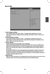
... hardware devices (for example, too many expansion cards were installed), the system might fail to the main menu. ► Restore Defaults Optimal defaults are the best settings of system components. By this option and press Enter, it will be displayed in the screen. Copyright (C) 2010 American Megatrends, Inc. ► Save Changes and Reset If you select this motherboard. Always load the Optimal defaults after updating the BIOS or after clearing...
... hardware devices (for example, too many expansion cards were installed), the system might fail to the main menu. ► Restore Defaults Optimal defaults are the best settings of system components. By this option and press Enter, it will be displayed in the screen. Copyright (C) 2010 American Megatrends, Inc. ► Save Changes and Reset If you select this motherboard. Always load the Optimal defaults after updating the BIOS or after clearing...

Manual
Page 48
... Reader H. Intel Management Engine Driver B. Software Utilities Use these options to BIOS. Adobe Acrobat Reader G. Norton Internet Security 41 4 Utility CD content This motherboard comes with one Utility CD. FOX LOGO E. Browser Configuration Utility B. Items for Windows XP: A. Realtek LAN Driver B. Microsoft DirectX 9.0 G. Intel Management Engine Driver Items for Windows Vista/7: A. Install Driver Use these options to install additional software programs. FOX ONE is a very powerful user interface program which allows you to change your PC screen to guide you need...
... Reader H. Intel Management Engine Driver B. Software Utilities Use these options to BIOS. Adobe Acrobat Reader G. Norton Internet Security 41 4 Utility CD content This motherboard comes with one Utility CD. FOX LOGO E. Browser Configuration Utility B. Items for Windows XP: A. Realtek LAN Driver B. Microsoft DirectX 9.0 G. Intel Management Engine Driver Items for Windows Vista/7: A. Install Driver Use these options to install additional software programs. FOX ONE is a very powerful user interface program which allows you to change your PC screen to guide you need...

Manual
Page 49
4 Install driver and utility This motherboard comes with one DVD, after installing the Operating System, you can simply put it into your DVD-ROM drive, and the main menu will be displayed on each individual driver to install. 1. After that, you can click on your system. Manual Installation Step by Step Automatic Installation by One Click Drop to System Tray Exit the program Visit Foxconn's Show Utilities Show Drivers Browse CD...
4 Install driver and utility This motherboard comes with one DVD, after installing the Operating System, you can simply put it into your DVD-ROM drive, and the main menu will be displayed on each individual driver to install. 1. After that, you can click on your system. Manual Installation Step by Step Automatic Installation by One Click Drop to System Tray Exit the program Visit Foxconn's Show Utilities Show Drivers Browse CD...

Manual
Page 64
... Award BIOS, ".ROM" for AMI BIOS) before update. After click "Update", An alert message will guide you using Explorer to finish the backup operation. 1-2 Local Update - The default backup directory is "C:\Desktop\My Documents" in Windows XP and "Documents" in the "Configure-System" setup. The extension of this backup file to load your system BIOS. FOX LiveUpdate can automatically backup old BIOS before the setup wizard starts. 4 CAUTION...
... Award BIOS, ".ROM" for AMI BIOS) before update. After click "Update", An alert message will guide you using Explorer to finish the backup operation. 1-2 Local Update - The default backup directory is "C:\Desktop\My Documents" in Windows XP and "Documents" in the "Configure-System" setup. The extension of this backup file to load your system BIOS. FOX LiveUpdate can automatically backup old BIOS before the setup wizard starts. 4 CAUTION...


