English Manual.
Page 1
Inferno Katana Series Motherboard User's Manual
Inferno Katana Series Motherboard User's Manual
English Manual.
Page 2
... consequences for specific features. Caution: refers to the physical motherboard for the environment and human health, which could otherwise be changed or modified at any time, Foxconn does not obligate itself to avoid problems. WARNING! For ...motherboard better, and tells you want more detailed information about our products, please visit Foxconn's website: http://www.foxconnchannel.com © All rights reserved. Although the information in this manual may be caused by inappropriate waste handling of Foxconn, Inc. All images are for Inferno Katana Series motherboard...
... consequences for specific features. Caution: refers to the physical motherboard for the environment and human health, which could otherwise be changed or modified at any time, Foxconn does not obligate itself to avoid problems. WARNING! For ...motherboard better, and tells you want more detailed information about our products, please visit Foxconn's website: http://www.foxconnchannel.com © All rights reserved. Although the information in this manual may be caused by inappropriate waste handling of Foxconn, Inc. All images are for Inferno Katana Series motherboard...
English Manual.
Page 3
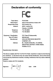
... information technology equipment ■ EN 61000-3-2/:2000 Electromagnetic compatibility (EMC) Part 3: Limits Section 2: Limits for harmonic current emissions (equipment input current declares that the product Motherboard Inferno Katana/Inferno Katana GTI is in conformity with (reference to the specification under which conformity is declared in accordance with 89/336 EEC-EMC Directive) ■ EN 55022...
... information technology equipment ■ EN 61000-3-2/:2000 Electromagnetic compatibility (EMC) Part 3: Limits Section 2: Limits for harmonic current emissions (equipment input current declares that the product Motherboard Inferno Katana/Inferno Katana GTI is in conformity with (reference to the specification under which conformity is declared in accordance with 89/336 EEC-EMC Directive) ■ EN 55022...
English Manual.
Page 4
...: Responsible Party: Address: Telephone: Facsimile: FOXCONN Inferno Katana/Inferno Katana GTI PCE Industry Inc. 458 E. Signature : Date : 2009 Supplementary Information: This device complies with FCC standards. Declaration of the FCC Rules. Fullerton, CA 92835 714-738-8868 714-738-8838 Equipment Classification: Type of Product: Manufacturer: Address: FCC Class B Subassembly Motherboard HON HAI PRECISION INDUSTRY COMPANY...
...: Responsible Party: Address: Telephone: Facsimile: FOXCONN Inferno Katana/Inferno Katana GTI PCE Industry Inc. 458 E. Signature : Date : 2009 Supplementary Information: This device complies with FCC standards. Declaration of the FCC Rules. Fullerton, CA 92835 714-738-8868 714-738-8838 Equipment Classification: Type of Product: Manufacturer: Address: FCC Class B Subassembly Motherboard HON HAI PRECISION INDUSTRY COMPANY...
English Manual.
Page 5
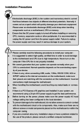
... been configured to the local standard. ■ To prevent damage to the motherboard, do not allow screws to your system. Incorrect connections might damage the motherboard. ■ When handling the motherboard, avoid touching any installation steps or have a problem related to the use of...device. ■ If there is suggested to select high-quality, certified fans in contact with the motherboard circuit or its components. Normal operation depends on the motherboard or within the computer casing. ■ If you are no leftover screws or metal components placed on...
... been configured to the local standard. ■ To prevent damage to the motherboard, do not allow screws to your system. Incorrect connections might damage the motherboard. ■ When handling the motherboard, avoid touching any installation steps or have a problem related to the use of...device. ■ If there is suggested to select high-quality, certified fans in contact with the motherboard circuit or its components. Normal operation depends on the motherboard or within the computer casing. ■ If you are no leftover screws or metal components placed on...
English Manual.
Page 8
Thank you for break-through performance. Foxconn products are engineered to maximize computing power, providing only what you to unleash more power from your computer. This chapter includes the following information: ■ Product Specifications ■ Layout ■ Back Panel Connectors With advanced overclocking capability and a range of connectivity features for today multi-media computing requirements, Inferno Katana/Inferno Katana GTI enables you need for buying Foxconn Inferno Katana Series motherboard.
Thank you for break-through performance. Foxconn products are engineered to maximize computing power, providing only what you to unleash more power from your computer. This chapter includes the following information: ■ Product Specifications ■ Layout ■ Back Panel Connectors With advanced overclocking capability and a range of connectivity features for today multi-media computing requirements, Inferno Katana/Inferno Katana GTI enables you need for buying Foxconn Inferno Katana Series motherboard.
English Manual.
Page 11
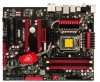
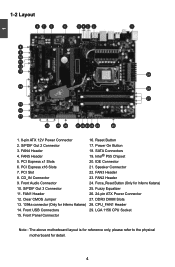
... 26. 24-pin ATX Power Connector 27. LGA 1156 CPU Socket Note : The above motherboard layout is for reference only, please refer to the physical motherboard for Inferno Katana) 14. PCI Express x1 Slots 6. FAN2 Header 24. Force_Reset Button (Only for Inferno Katana) 25. Front Audio Connector 10. Front USB Connectors 15. CPU_FAN1 Header 29. FAN5...
... 26. 24-pin ATX Power Connector 27. LGA 1156 CPU Socket Note : The above motherboard layout is for reference only, please refer to the physical motherboard for Inferno Katana) 14. PCI Express x1 Slots 6. FAN2 Header 24. Force_Reset Button (Only for Inferno Katana) 25. Front Audio Connector 10. Front USB Connectors 15. CPU_FAN1 Header 29. FAN5...
English Manual.
Page 14
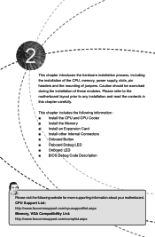
... ■ Onboard LED ■ BIOS Debug Code Description Please visit the following website for more supporting information about your motherboard. CPU Support List: http://www.foxconnsupport.com/cpusupportlist.aspx Memory, VGA Compatibility List: http://www.foxconnsupport.com/complist.aspx Please refer ...to the motherboard layout prior to any installation and read the contents in this chapter carefully. This chapter introduces the hardware installation process...
... ■ Onboard LED ■ BIOS Debug Code Description Please visit the following website for more supporting information about your motherboard. CPU Support List: http://www.foxconnsupport.com/cpusupportlist.aspx Memory, VGA Compatibility List: http://www.foxconnsupport.com/complist.aspx Please refer ...to the motherboard layout prior to any installation and read the contents in this chapter carefully. This chapter introduces the hardware installation process...
English Manual.
Page 15
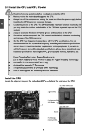
... CPU to prevent hardware damage. ■ Locate the pin one of the CPU. If you begin to install the CPU: ■ Make sure that the motherboard supports the CPU. ■ Always turn off the computer and unplug the power cord from the power supply before you wish to set beyond the... that supports HT Technology ■ An operating system that supports HT Technology and has it enabled Install the CPU Locate the alignment keys on the motherboard CPU socket and the notches on the computer if the CPU cooler is not installed, otherwise overheating and damage of the CPU may locate the...
... CPU to prevent hardware damage. ■ Locate the pin one of the CPU. If you begin to install the CPU: ■ Make sure that the motherboard supports the CPU. ■ Always turn off the computer and unplug the power cord from the power supply before you wish to set beyond the... that supports HT Technology ■ An operating system that supports HT Technology and has it enabled Install the CPU Locate the alignment keys on the motherboard CPU socket and the notches on the computer if the CPU cooler is not installed, otherwise overheating and damage of the CPU may locate the...
English Manual.
Page 17
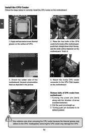
...2. Install the CPU Cooler Follow the steps below to correctly install the CPU cooler on the motherboard. Turning push pin clockwise to the holes of the motherboard, the push pin should be fastened on the motherboard. 2 CAUTION 1. Inadequately removing the CPU cooler may adhere to the CPU. That's it.... 3. Check the solder side of the motherboard, push them straight down from motherboard : 1.Turning the push pin (bolt) along with the direction of CPU. 2. Pull the push pin straight up. 3. Use ...
...2. Install the CPU Cooler Follow the steps below to correctly install the CPU cooler on the motherboard. Turning push pin clockwise to the holes of the motherboard, the push pin should be fastened on the motherboard. 2 CAUTION 1. Inadequately removing the CPU cooler may adhere to the CPU. That's it.... 3. Check the solder side of the motherboard, push them straight down from motherboard : 1.Turning the push pin (bolt) along with the direction of CPU. 2. Pull the push pin straight up. 3. Use ...
English Manual.
Page 18
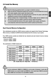
...SS DS/SS (DS : Double Side, SS : Single Side, - : No Memory) DS/SS DS/SS DS/SS ! ■ For this motherboard, DIMM(1,2), DIMM(3,4), are unable to prevent hardware damage. ■ Memory modules have a foolproof design. In each channel has two memory sockets as following ...guidelines before installing the memory to insert the memory, switch the direction. ■ It is recommended that the motherboard supports the memory. Read the following : Channel 0: DIMM1, DIMM2 Channel 1: DIMM3, DIMM4 The combinations of DIMM modules are divided into...
...SS DS/SS (DS : Double Side, SS : Single Side, - : No Memory) DS/SS DS/SS DS/SS ! ■ For this motherboard, DIMM(1,2), DIMM(3,4), are unable to prevent hardware damage. ■ Memory modules have a foolproof design. In each channel has two memory sockets as following ...guidelines before installing the memory to insert the memory, switch the direction. ■ It is recommended that the motherboard supports the memory. Read the following : Channel 0: DIMM1, DIMM2 Channel 1: DIMM3, DIMM4 The combinations of DIMM modules are divided into...
English Manual.
Page 19
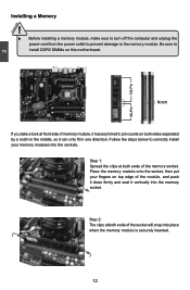
..., make sure to turn off the computer and unplug the power cord from the power outlet to prevent damage to install DDR3 DIMMs on this motherboard. Notch If you take a look at front side of memory module, it has asymmetric pin counts on top edge of the memory socket. Follow the...
..., make sure to turn off the computer and unplug the power cord from the power outlet to prevent damage to install DDR3 DIMMs on this motherboard. Notch If you take a look at front side of memory module, it has asymmetric pin counts on top edge of the memory socket. Follow the...
English Manual.
Page 20
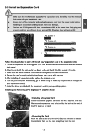
... expansion card in the slot. 3. Secure the card's metal bracket to correctly install your operating system. CAUTION 2 2-3 Install an Expansion Card ! ■ Make sure the motherboard supports the expansion card.
... expansion card in the slot. 3. Secure the card's metal bracket to correctly install your operating system. CAUTION 2 2-3 Install an Expansion Card ! ■ Make sure the motherboard supports the expansion card.
English Manual.
Page 21
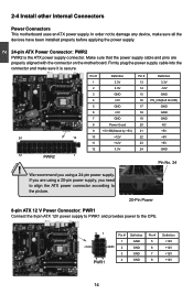
... an ATX power supply. If you are properly aligned with the connector on the motherboard. Pin No. 24 20-Pin Power 8-pin ATX 12 V Power Connector: PWR1 Connect the 8-pin ATX 12V power supply to PWR1 and provides power to ...
... an ATX power supply. If you are properly aligned with the connector on the motherboard. Pin No. 24 20-Pin Power 8-pin ATX 12 V Power Connector: PWR1 Connect the 8-pin ATX 12V power supply to PWR1 and provides power to ...

English Manual.
Page 22
... this product also provides three 10-pin USB headers on the right. Speaker Connector: SPEAKER The speaker connector is used to the picture on its motherboard. We recommend you can quickly expand another six USB ports on the front panel. 12 VCC DD+ GND EMPTY VCC DD+ GND NC 9 10 F_USB...
... this product also provides three 10-pin USB headers on the right. Speaker Connector: SPEAKER The speaker connector is used to the picture on its motherboard. We recommend you can quickly expand another six USB ports on the front panel. 12 VCC DD+ GND EMPTY VCC DD+ GND NC 9 10 F_USB...
English Manual.
Page 23
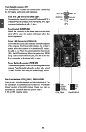
2 Front Panel Connector: FP1 This motherboard includes one connector for connecting the front panel switch and LED Indicators. sign. Reset Switch (RESET-SW) Attach the connector to the Reset switch on ...the front panel of the hard disks. When the system gets into sleep mode (S1) , the LED is pressed. Push this motherboard. This 2-pin connector is on and off after the system enters 3, S4 and S5 sleeping states. 1 GND 1 GND POWER +12V SENSE NC CONTROL CPU_FAN1 FAN1...
2 Front Panel Connector: FP1 This motherboard includes one connector for connecting the front panel switch and LED Indicators. sign. Reset Switch (RESET-SW) Attach the connector to the Reset switch on ...the front panel of the hard disks. When the system gets into sleep mode (S1) , the LED is pressed. Push this motherboard. This 2-pin connector is on and off after the system enters 3, S4 and S5 sleeping states. 1 GND 1 GND POWER +12V SENSE NC CONTROL CPU_FAN1 FAN1...
English Manual.
Page 25
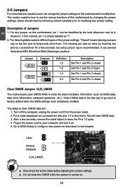
.... After a few seconds, but using jumper cap is simply labeled as BIOS data, date, time information, hardware password...etc.). Plug in this motherboard by changing the jumper settings. WARNING! 1 Clear 2 Normal 1 (Default) 2 CLR_CMOS ■ Disconnect the power cable before adjusting the jumper settings... Pin 1 and Pin 2 Open Set Pin 1 and Pin 2 closed Set Pin 2 and Pin 3 closed Clear CMOS Jumper: CLR_CMOS The motherboard uses CMOS RAM to store the basic hardware information (such as "1". 2. For any jumper setting. The steps to temporarily short them . Users...
.... After a few seconds, but using jumper cap is simply labeled as BIOS data, date, time information, hardware password...etc.). Plug in this motherboard by changing the jumper settings. WARNING! 1 Clear 2 Normal 1 (Default) 2 CLR_CMOS ■ Disconnect the power cable before adjusting the jumper settings... Pin 1 and Pin 2 Open Set Pin 1 and Pin 2 closed Set Pin 2 and Pin 3 closed Clear CMOS Jumper: CLR_CMOS The motherboard uses CMOS RAM to store the basic hardware information (such as "1". 2. For any jumper setting. The steps to temporarily short them . Users...
English Manual.
Page 27
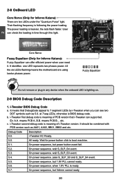
...ready. 5.6. User can see two DOT symbols such as AA01, AA02, BB01, BB02 and etc. All the six LEDs flashing means the motherboard are ten LEDs under the "Quantum Force" light. i-Tweaker BIOS Debug Code a. means PCB A, B.B. It should be combined with PCB version...of i-Tweaker version. Debug Code Description 0.0. Ex: A.A. c. i-Tweaker first debug code is ready. 5.7. 2-8 OnBoard LED Core Nerve (Only for Inferno Katana): There are using twelve phases power. Their flashing frequency is following the power loading. On power sequence, but power button event fail. 5.2. It ...
...ready. 5.6. User can see two DOT symbols such as AA01, AA02, BB01, BB02 and etc. All the six LEDs flashing means the motherboard are ten LEDs under the "Quantum Force" light. i-Tweaker BIOS Debug Code a. means PCB A, B.B. It should be combined with PCB version...of i-Tweaker version. Debug Code Description 0.0. Ex: A.A. c. i-Tweaker first debug code is ready. 5.7. 2-8 OnBoard LED Core Nerve (Only for Inferno Katana): There are using twelve phases power. Their flashing frequency is following the power loading. On power sequence, but power button event fail. 5.2. It ...
English Manual.
Page 39
... or you can select AHCI to select the mechanism for detecting 80Pin ATA(PI) Cable. This item allows you select the mode of the motherboard. Setting values are: [Disabled], [Enhanced]. ► Primary/Secondary IDE Master/Slave, Third/Fourth IDE Master While entering setup, BIOS automatically detects... the presence of the motherboard. If the checking time is over the set to[RAID]/[AHCI]) This item is used to enable or disable hot plug function for SATA...
... or you can select AHCI to select the mechanism for detecting 80Pin ATA(PI) Cable. This item allows you select the mode of the motherboard. Setting values are: [Disabled], [Enhanced]. ► Primary/Secondary IDE Master/Slave, Third/Fourth IDE Master While entering setup, BIOS automatically detects... the presence of the motherboard. If the checking time is over the set to[RAID]/[AHCI]) This item is used to enable or disable hot plug function for SATA...
English Manual.
Page 40
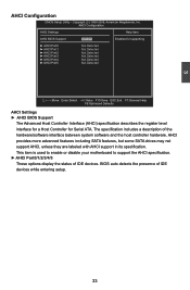
... and the host controller hardware. The specification includes a description of IDE devices while entering setup. 33 This item is used to enable or disable your motherboard to support the AHCI specification. ► AHCI Port0/1/2/3/4/5 These options display the status of IDE devices. AHCI Configuration AHCI Settings Help Item AHCI BIOS Support...
... and the host controller hardware. The specification includes a description of IDE devices while entering setup. 33 This item is used to enable or disable your motherboard to support the AHCI specification. ► AHCI Port0/1/2/3/4/5 These options display the status of IDE devices. AHCI Configuration AHCI Settings Help Item AHCI BIOS Support...


