
User Manual
Page 4
8808A Users Manual Storing and Shipping the Meter 2-3 Power Considerations 2-3 Selecting the Line Voltage 2-4 Replacing the Fuses 2-4 Line-Power Fuse 2-4 Current-Input Fuses 2-5 Connecting to Line Power 2-7 Turning Power On 2-8 Adjusting the Bail 2-8 Installing the Meter into an Equipment Rack 2-8 Cleaning the Meter 2-9 Fluke 45 Emulation 2-9 Illuminating All Display ... the Number Editor 3-24 Function Keys S1 - S6 3-24 Power-Up Configuration 3-25 Factory Settings of Power-Up Configuration 3-25 Calibration ...3-26 4 Operating the Meter Using the Computer Interface 4-1 ii
8808A Users Manual Storing and Shipping the Meter 2-3 Power Considerations 2-3 Selecting the Line Voltage 2-4 Replacing the Fuses 2-4 Line-Power Fuse 2-4 Current-Input Fuses 2-5 Connecting to Line Power 2-7 Turning Power On 2-8 Adjusting the Bail 2-8 Installing the Meter into an Equipment Rack 2-8 Cleaning the Meter 2-9 Fluke 45 Emulation 2-9 Illuminating All Display ... the Number Editor 3-24 Function Keys S1 - S6 3-24 Power-Up Configuration 3-25 Factory Settings of Power-Up Configuration 3-25 Calibration ...3-26 4 Operating the Meter Using the Computer Interface 4-1 ii

User Manual
Page 13
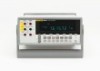
... serves as the Meter) is within defined limits • Remote operation via the RS-232 interface • Closed-case calibration (no internal calibration adjustments) Manual Set The manual set for this Meter consists of 2.5, 20 and 100 samples/second (slow, medium and ...a 5-1/2 digit dual-display multimeter designed for bench-top, field service, and system applications. 1 Introduction and Specifications Introduction Introduction The Fluke 8808A Digital Multimeter (hereafter referred to as a bail for bench-top operation. The multiple measurement functions, plus the RS-232 remote interface...
... serves as the Meter) is within defined limits • Remote operation via the RS-232 interface • Closed-case calibration (no internal calibration adjustments) Manual Set The manual set for this Meter consists of 2.5, 20 and 100 samples/second (slow, medium and ...a 5-1/2 digit dual-display multimeter designed for bench-top, field service, and system applications. 1 Introduction and Specifications Introduction Introduction The Fluke 8808A Digital Multimeter (hereafter referred to as a bail for bench-top operation. The multiple measurement functions, plus the RS-232 remote interface...

User Manual
Page 36
8808A Users Manual Calibration ...3-25 3-2
8808A Users Manual Calibration ...3-25 3-2

User Manual
Page 38
...Compare function for determining if a reading falls within a designated range of values For storage and retrieval of up to six test configurations Calibrates Meter Activates/deactivates standby mode for power savings Activates second level operation for Volts, 2-Wire and 4-Wire Ohms, and Hz measurements. ... panel operation during remote mode Primary operation: Selects Meter print mode Second level operation: Sets RS-232 communication parameters (baud rate, parity, echo) 3-4 8808A Users Manual 1 2 3 4 2W/4W HI INPUT V SENSE 4W HI 1000V 750V MAX LO 200 mA MAX 1000 V 600 V CAT I ...
...Compare function for determining if a reading falls within a designated range of values For storage and retrieval of up to six test configurations Calibrates Meter Activates/deactivates standby mode for power savings Activates second level operation for Volts, 2-Wire and 4-Wire Ohms, and Hz measurements. ... panel operation during remote mode Primary operation: Selects Meter print mode Second level operation: Sets RS-232 communication parameters (baud rate, parity, echo) 3-4 8808A Users Manual 1 2 3 4 2W/4W HI INPUT V SENSE 4W HI 1000V 750V MAX LO 200 mA MAX 1000 V 600 V CAT I ...

User Manual
Page 41
... is in RS-232 print-only mode Flashes for each Meter sample cycle Meter is in auto range mode Meter is in manual range mode Calibration attempt failed High voltage is detected Displays when voltage is >30 V dc or ac rms 3-7 3 Operating the Meter from the Front Panel Dual Display Table...
... is in RS-232 print-only mode Flashes for each Meter sample cycle Meter is in auto range mode Meter is in manual range mode Calibration attempt failed High voltage is detected Displays when voltage is >30 V dc or ac rms 3-7 3 Operating the Meter from the Front Panel Dual Display Table...

User Manual
Page 59
...Minimum and maximum values in MIN MAX modifier 0 Relative base 0 Relative base in secondary display Disabled Trigger type 1 (Internal) Trigger trype 0 Calibration Refer to the power-up configuration listed in compare mode • Trigger mode (1, 2, 3, 4, 5) • Echo setting (on or off... • Last recorded minimum and maximum values for instructions on and the power-up sequence is complete, the Meter defaults to the 8808A Calibration Manual for MINMAX modifier • Last recorded relative base • Relative base shown in secondary display (enabled or disabled) •...
...Minimum and maximum values in MIN MAX modifier 0 Relative base 0 Relative base in secondary display Disabled Trigger type 1 (Internal) Trigger trype 0 Calibration Refer to the power-up configuration listed in compare mode • Trigger mode (1, 2, 3, 4, 5) • Echo setting (on or off... • Last recorded minimum and maximum values for instructions on and the power-up sequence is complete, the Meter defaults to the 8808A Calibration Manual for MINMAX modifier • Last recorded relative base • Relative base shown in secondary display (enabled or disabled) •...

User Manual
Page 74
...command line before receipt of Bits in output buffer. Description of enabled events in the Status Byte Register (STB) Bit No. to 0. 8808A Users Manual 4-14 Table 4-6. One or more of Bits in the Event Status Register have occurred. Name Condition 0 Operation Complete (OPC... in Table 4-7, and are described in output buffer. Or input and output buffers were full. 3 Device-Dependent Error (DDE) Incorrect input during calibration. Data is a binary-encoded register that contained a syntax error. 6 Not used 4 Message Available (MAV) 5 Event Status (ESB) Condition ...
...command line before receipt of Bits in output buffer. Description of enabled events in the Status Byte Register (STB) Bit No. to 0. 8808A Users Manual 4-14 Table 4-6. One or more of Bits in the Event Status Register have occurred. Name Condition 0 Operation Complete (OPC... in Table 4-7, and are described in output buffer. Or input and output buffers were full. 3 Device-Dependent Error (DDE) Incorrect input during calibration. Data is a binary-encoded register that contained a syntax error. 6 Not used 4 Message Available (MAV) 5 Event Status (ESB) Condition ...

