
FE 83V & 87V Users Manual
Page 1
All product names are trademarks of their respective companies. Users Manual ® 80 Series V Multimeters May 2004 Rev. 1, 8/04 2004 Fluke Corporation, All rights reserved.
All product names are trademarks of their respective companies. Users Manual ® 80 Series V Multimeters May 2004 Rev. 1, 8/04 2004 Fluke Corporation, All rights reserved.
FE 83V & 87V Users Manual
Page 4
80 Series V Users Manual Measuring AC or DC Current 24 Measuring Frequency 27 Measuring Duty Cycle 29 Determining Pulse Width 30 Bar Graph...30 Zoom Mode (Power Up Option Only 31 Uses for the Zoom Mode 31 HiRes Mode (Model 87) ...31 MIN MAX Recording Mode 32 Smooth Feature (Power Up Option Only 32 AutoHOLD Mode...34 Relative Mode ...34 Maintenance...35 General Maintenance...35 Fuse Test ...35 Replacing the Battery...36 Replacing the Fuses ...37 Service and Parts...37 Specifications ...43 Detailed Specifications 44 ii
80 Series V Users Manual Measuring AC or DC Current 24 Measuring Frequency 27 Measuring Duty Cycle 29 Determining Pulse Width 30 Bar Graph...30 Zoom Mode (Power Up Option Only 31 Uses for the Zoom Mode 31 HiRes Mode (Model 87) ...31 MIN MAX Recording Mode 32 Smooth Feature (Power Up Option Only 32 AutoHOLD Mode...34 Relative Mode ...34 Maintenance...35 General Maintenance...35 Fuse Test ...35 Replacing the Battery...36 Replacing the Fuses ...37 Service and Parts...37 Specifications ...43 Detailed Specifications 44 ii
FE 83V & 87V Users Manual
Page 6
80 Series V Users Manual iv
80 Series V Users Manual iv

FE 83V & 87V Users Manual
Page 10
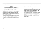
Pay particular attention to the user. Look for cracks or missing plastic. XWWarning To avoid possible electric shock or personal injury, follow these guidelines: • Use this Meter only as specified in this manual are explained in this manual or the protection provided by the Meter might...8226; Remove test leads from the Meter before opening the battery door. 2 Electrical symbols used on the Meter and in Table 1. 80 Series V Users Manual Safety Information The Meter complies with: • EN61010-1:2001 • ANSI/ISA S82.01-2004 • CAN/CSA C22.2 No. 1010.1:2004 &#...
Pay particular attention to the user. Look for cracks or missing plastic. XWWarning To avoid possible electric shock or personal injury, follow these guidelines: • Use this Meter only as specified in this manual are explained in this manual or the protection provided by the Meter might...8226; Remove test leads from the Meter before opening the battery door. 2 Electrical symbols used on the Meter and in Table 1. 80 Series V Users Manual Safety Information The Meter complies with: • EN61010-1:2001 • ANSI/ISA S82.01-2004 • CAN/CSA C22.2 No. 1010.1:2004 &#...

FE 83V & 87V Users Manual
Page 12
80 Series V Users Manual WCaution To avoid possible damage to the Meter or to the equipment under test, follow these guidelines: • Disconnect circuit power and discharge all high-voltage capacitors before testing resistance, continuity, diodes, or capacitance. • Use the proper terminals, function, and range for all measurements. • Before measuring current, check the Meter's fuses. (See "Fuse Test".) 4
80 Series V Users Manual WCaution To avoid possible damage to the Meter or to the equipment under test, follow these guidelines: • Disconnect circuit power and discharge all high-voltage capacitors before testing resistance, continuity, diodes, or capacitance. • Use the proper terminals, function, and range for all measurements. • Before measuring current, check the Meter's fuses. (See "Fuse Test".) 4

FE 83V & 87V Users Manual
Page 14
Input for 0 µA to 10.00 A current (20 A overload for voltage, continuity, resistance, diode, capacitance, frequency, temperature (87), and duty cycle measurements. 6 Return terminal for 18 hrs.) and current frequency and duty cycle. Inputs Terminal A mA µA COM I Description Input for 0 A to 400 mA current measurements (600 mA for all measurements. Input for 30 seconds maximum), current frequency, and duty cycle measurements. 80 Series V Users Manual The Meter's Features Tables 2 through 5 briefly describe the Meter's features. Table 2.
Input for 0 µA to 10.00 A current (20 A overload for voltage, continuity, resistance, diode, capacitance, frequency, temperature (87), and duty cycle measurements. 6 Return terminal for 18 hrs.) and current frequency and duty cycle. Inputs Terminal A mA µA COM I Description Input for 0 A to 400 mA current measurements (600 mA for all measurements. Input for 30 seconds maximum), current frequency, and duty cycle measurements. 80 Series V Users Manual The Meter's Features Tables 2 through 5 briefly describe the Meter's features. Table 2.

FE 83V & 87V Users Manual
Page 16
... dc and ac current Disables automatic power-off feature (Meter normally powers off in 30 minutes). The Meter reads "5___" until A is released. 8 80 Series V Users Manual Button A (Yellow) B C Table 4. Cancels MIN MAX (hold the button down for the selected function.
... dc and ac current Disables automatic power-off feature (Meter normally powers off in 30 minutes). The Meter reads "5___" until A is released. 8 80 Series V Users Manual Button A (Yellow) B C Table 4. Cancels MIN MAX (hold the button down for the selected function.

FE 83V & 87V Users Manual
Page 18
... switch position Function Stores the present reading as a reference for subsequent readings. Starts the frequency counter. The Meter reads "2rEL" until G is used. 80 Series V Users Manual Button F (Relative mode) G Table 4.
... switch position Function Stores the present reading as a reference for subsequent readings. Starts the frequency counter. The Meter reads "2rEL" until G is used. 80 Series V Users Manual Button F (Relative mode) G Table 4.

FE 83V & 87V Users Manual
Page 20
... V, mV µF, nF nS % e, Me, ke Hz, kHz AC DC N °C, °F O 610000 mV P HiRes Auto Q Manual Indication Amperes (amps), Microamp, Milliamp Volts, Millivolts Microfarad, Nanofarad Nanosiemens Percent. Invalid calibration data. Calibrate Meter. 80 Series V Users Manual Table 5. Have Meter serviced. The bar graph also has a zoom function, as described under "Zoom Mode...
... V, mV µF, nF nS % e, Me, ke Hz, kHz AC DC N °C, °F O 610000 mV P HiRes Auto Q Manual Indication Amperes (amps), Microamp, Milliamp Volts, Millivolts Microfarad, Nanofarad Nanosiemens Percent. Invalid calibration data. Calibrate Meter. 80 Series V Users Manual Table 5. Have Meter serviced. The bar graph also has a zoom function, as described under "Zoom Mode...

FE 83V & 87V Users Manual
Page 22
This procedure improves the accuracy of an ac voltage, measure the ac voltage first. 80 Series V Users Manual When measuring voltage, the Meter acts approximately like a 10 MΩ (10,000,000 Ω) impedance in high-impedance circuits. For better accuracy when measuring the ....eps Figure 2. Measuring AC and DC Voltage This loading effect can cause measurement errors in parallel with the circuit. Note the ac voltage range, then manually select a dc voltage range equal to or higher than the ac range. In most cases, the error is negligible (0.1% or less) if the circuit impedance...
This procedure improves the accuracy of an ac voltage, measure the ac voltage first. 80 Series V Users Manual When measuring voltage, the Meter acts approximately like a 10 MΩ (10,000,000 Ω) impedance in high-impedance circuits. For better accuracy when measuring the ....eps Figure 2. Measuring AC and DC Voltage This loading effect can cause measurement errors in parallel with the circuit. Note the ac voltage range, then manually select a dc voltage range equal to or higher than the ac range. In most cases, the error is negligible (0.1% or less) if the circuit impedance...

FE 83V & 87V Users Manual
Page 24
... watch the display. Display ranges are -200.0 °C to +1090.0 °C and -328.0 °F to choose Celsius or Fahrenheit. Push C to 1994.0 °F. 80 Series V Users Manual Measuring Temperature (87) The Meter measures the temperature of these ranges show OL on or off. M 2. To test for -200.0 °C to +1090.0 °C and...
... watch the display. Display ranges are -200.0 °C to +1090.0 °C and -328.0 °F to choose Celsius or Fahrenheit. Push C to 1994.0 °F. 80 Series V Users Manual Measuring Temperature (87) The Meter measures the temperature of these ranges show OL on or off. M 2. To test for -200.0 °C to +1090.0 °C and...
FE 83V & 87V Users Manual
Page 26
... capacitors before measuring resistance. Refer to Table 18. 18 To measure resistance, set up the Meter as shown in the next higher range. 80 Series V Users Manual Measuring Resistance WCaution To avoid possible damage to the Meter or to the equipment under test, disconnect circuit power and discharge all paths between the...
... capacitors before measuring resistance. Refer to Table 18. 18 To measure resistance, set up the Meter as shown in the next higher range. 80 Series V Users Manual Measuring Resistance WCaution To avoid possible damage to the Meter or to the equipment under test, disconnect circuit power and discharge all paths between the...

FE 83V & 87V Users Manual
Page 28
... susceptible to pass current. High values of conductance correspond to low values of components up the Meter as shown for measuring resistance (Figure 5); 80 Series V Users Manual Using Conductance for High Resistance or Leakage Tests Conductance, the inverse of resistance, is normally a residual conductance reading with the test leads open.
... susceptible to pass current. High values of conductance correspond to low values of components up the Meter as shown for measuring resistance (Figure 5); 80 Series V Users Manual Using Conductance for High Resistance or Leakage Tests Conductance, the inverse of resistance, is normally a residual conductance reading with the test leads open.

FE 83V & 87V Users Manual
Page 30
... junction drops between the probe tips. This function tests a semiconductor junction by sending a current through the junction, then measuring the junction's voltage drop. 80 Series V Users Manual Testing Diodes WCaution To avoid possible damage to the Meter or to the equipment under test, disconnect circuit power and discharge all high-voltage capacitors...
... junction drops between the probe tips. This function tests a semiconductor junction by sending a current through the junction, then measuring the junction's voltage drop. 80 Series V Users Manual Testing Diodes WCaution To avoid possible damage to the Meter or to the equipment under test, disconnect circuit power and discharge all high-voltage capacitors...

FE 83V & 87V Users Manual
Page 32
... test: • Check the Meter's fuses before measuring current. • Use the proper terminals, function, and range for 18 hours or less. 24 80 Series V Users Manual Measuring AC or DC Current XWWarning To avoid possible electric shock or personal injury, never attempt an in-circuit current measurement where the open-circuit...
... test: • Check the Meter's fuses before measuring current. • Use the proper terminals, function, and range for 18 hours or less. 24 80 Series V Users Manual Measuring AC or DC Current XWWarning To avoid possible electric shock or personal injury, never attempt an in-circuit current measurement where the open-circuit...

FE 83V & 87V Users Manual
Page 34
..., test the Meter's fuses as described under "Testing the Fuses". • A current Meter drops a small voltage across itself, which might affect circuit operation. 80 Series V Users Manual 3.
..., test the Meter's fuses as described under "Testing the Fuses". • A current Meter drops a small voltage across itself, which might affect circuit operation. 80 Series V Users Manual 3.
FE 83V & 87V Users Manual
Page 36
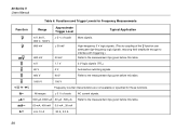
... with triggering.) Refer to the measurement tips given before this table. Refer to the measurement tips given before this table. 5 V logic signals (TTL). 80 Series V Users Manual Table 6. Automotive switching signals. R e E Gd Frequency counter characteristics are not available or specified for Frequency Measurements Function K K mL L L L L Range 6 V, 60 V, 600 V, 1000 V 600 mV 600...
... with triggering.) Refer to the measurement tips given before this table. Refer to the measurement tips given before this table. 5 V logic signals (TTL). 80 Series V Users Manual Table 6. Automotive switching signals. R e E Gd Frequency counter characteristics are not available or specified for Frequency Measurements Function K K mL L L L L Range 6 V, 60 V, 600 V, 1000 V 600 mV 600...
FE 83V & 87V Users Manual
Page 38
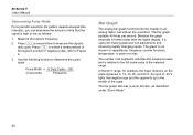
... represent 0, 15, 30, 45, and 60 V. In the 60 V range, for example, the major divisions on an analog meter, but without the overshoot. 80 Series V Users Manual Determining Pulse Width For a periodic waveform (its pattern repeats at equal time intervals), you can determine the amount of the selected range. Measure the signal...
... represent 0, 15, 30, 45, and 60 V. In the 60 V range, for example, the major divisions on an analog meter, but without the overshoot. 80 Series V Users Manual Determining Pulse Width For a periodic waveform (its pattern repeats at equal time intervals), you can determine the amount of the selected range. Measure the signal...
FE 83V & 87V Users Manual
Page 40
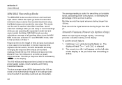
... unstable inputs, calculating power consumption, or estimating the percentage of recording (overloads are operating the equipment under test and cannot watch the Meter. 80 Series V Users Manual MIN MAX Recording Mode The MIN MAX mode records minimum and maximum input values. This mode can also calculate an average of all readings taken...
... unstable inputs, calculating power consumption, or estimating the percentage of recording (overloads are operating the equipment under test and cannot watch the Meter. 80 Series V Users Manual MIN MAX Recording Mode The MIN MAX mode records minimum and maximum input values. This mode can also calculate an average of all readings taken...
FE 83V & 87V Users Manual
Page 42
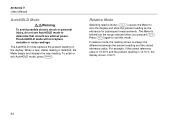
... the display and store the present reading as the reference for subsequent measurements. The Meter is 14.10 V, the display shows -0.90 V. 34 80 Series V Users Manual AutoHOLD Mode XWWarning To avoid possible electric shock or personal injury, do not use AutoHOLD mode to determine that circuits are without power. When a new...
... the display and store the present reading as the reference for subsequent measurements. The Meter is 14.10 V, the display shows -0.90 V. 34 80 Series V Users Manual AutoHOLD Mode XWWarning To avoid possible electric shock or personal injury, do not use AutoHOLD mode to determine that circuits are without power. When a new...


